I’ve gotten away from using the probe in CNCjs or UGS in favor of the cigarette paper test because I oftern cut from the interior of a piece of stock and don’t have any corners to do an X or Y, and the paper is faster and easier if I’m only doing Z. I think Heyward has been using the probe - maybe he can provide some more detail.
Hi Rob and everyone,
I’m new here and in CNCing as well )))
I’ve got a long mill recently and also got a spindle from Amazon almost like yours.
I saw your instructions for how to setup a spindle but you were saying that you would do more detail instruction with pics!  if I may ask, by any chance have you done that?
Thanks a lot
Hi Rob,
Can you (or anyone) please take a pic. how are you attached your spindle to LM?
Thanks
BTW, Merry Christmas everyone!!!
All,
Apologize for the really late reply on the requests. I’ll get some pictures and better instructions typed up by the end of the week.
I’ve received a couple requests on how I was able to wire up a VFD with the LongBoard. There’s really three parts to this. 1. Settng up the VFD software, 2. Wiring the VFD to the LongBoard and spindle and 3. Controlling the VFD/spindle using gCode with your gCode software/CAM software of choice (in my case Vectric Vcarve)
1. Setting up the VFD
This is very dependent on the spindle and VFD you own, but for this tutorial I used a 220v water cooled Chinese spindle and I’ve posted my VFD settings above. Big thing to note is the LongBoard outputs 5vDC for Spindle PWM so you’ll need to do the math for settings PD70 and PD144 based on that. The settings I used above should work for most 220V 24,000RPM spindles.
2. Wiring the LongBoard to the VFD
I’ve got to be honest, this was a lot of trial and error. I’m still not 100% sure why my wiring works, but I’ll give you some pictures and hopefully a smarter electrical engineer can fill in the gaps.
First a picture:
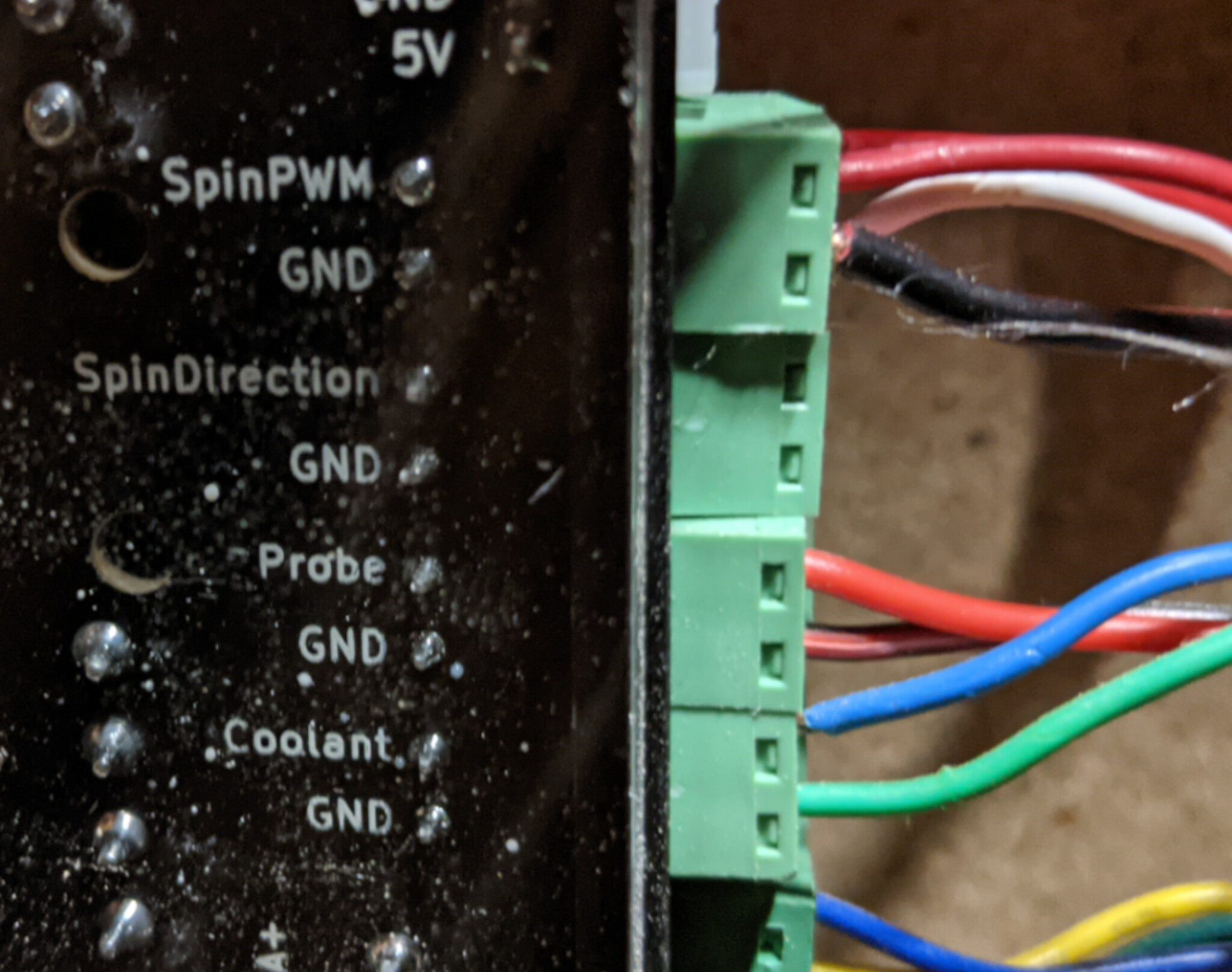
LongBoard Wiring
SpinPWM: Red Wire
SpinPWM Ground: White Wire
Coolant: Blue Wire
Coolant Ground: Green Wire
You’ll notice I have an additional Red Wire and Black wire for SpinPWM. That’s used to control my Laser TTL. Another tutorial, for another day. ![]()
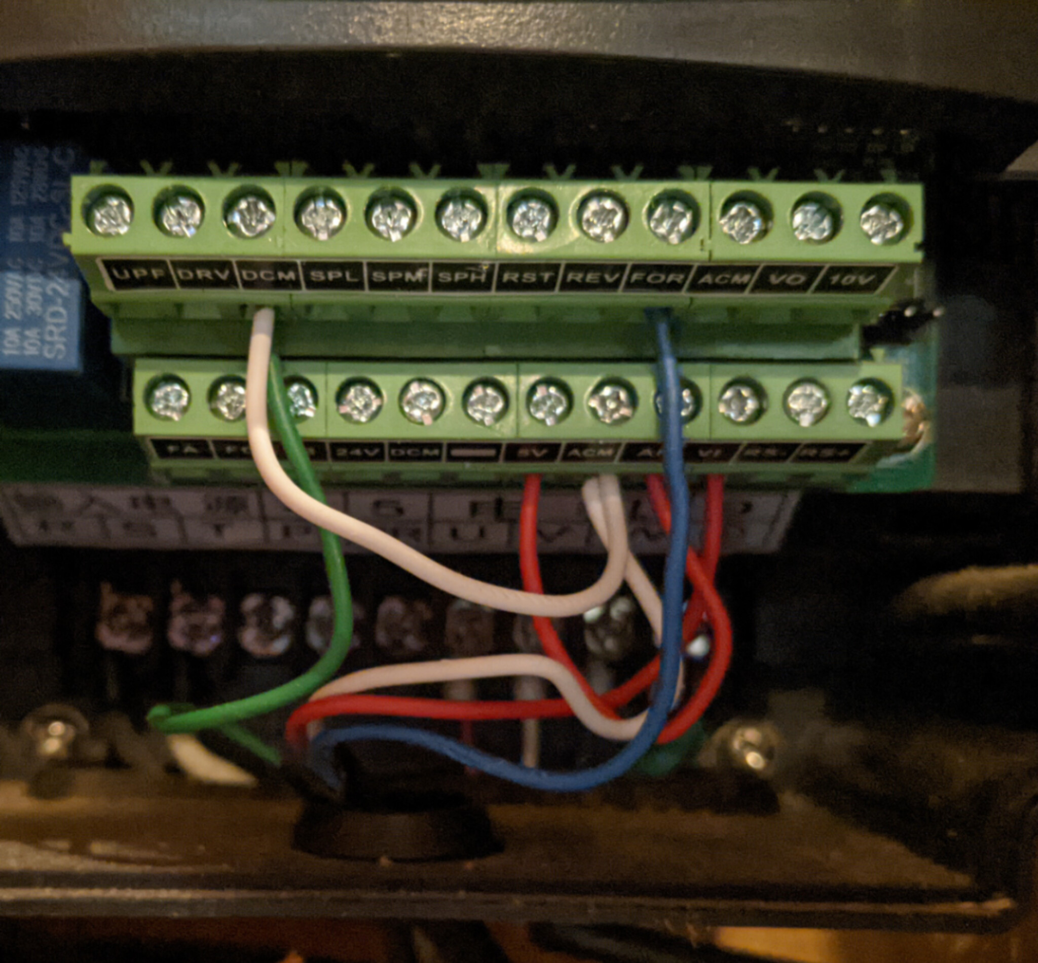
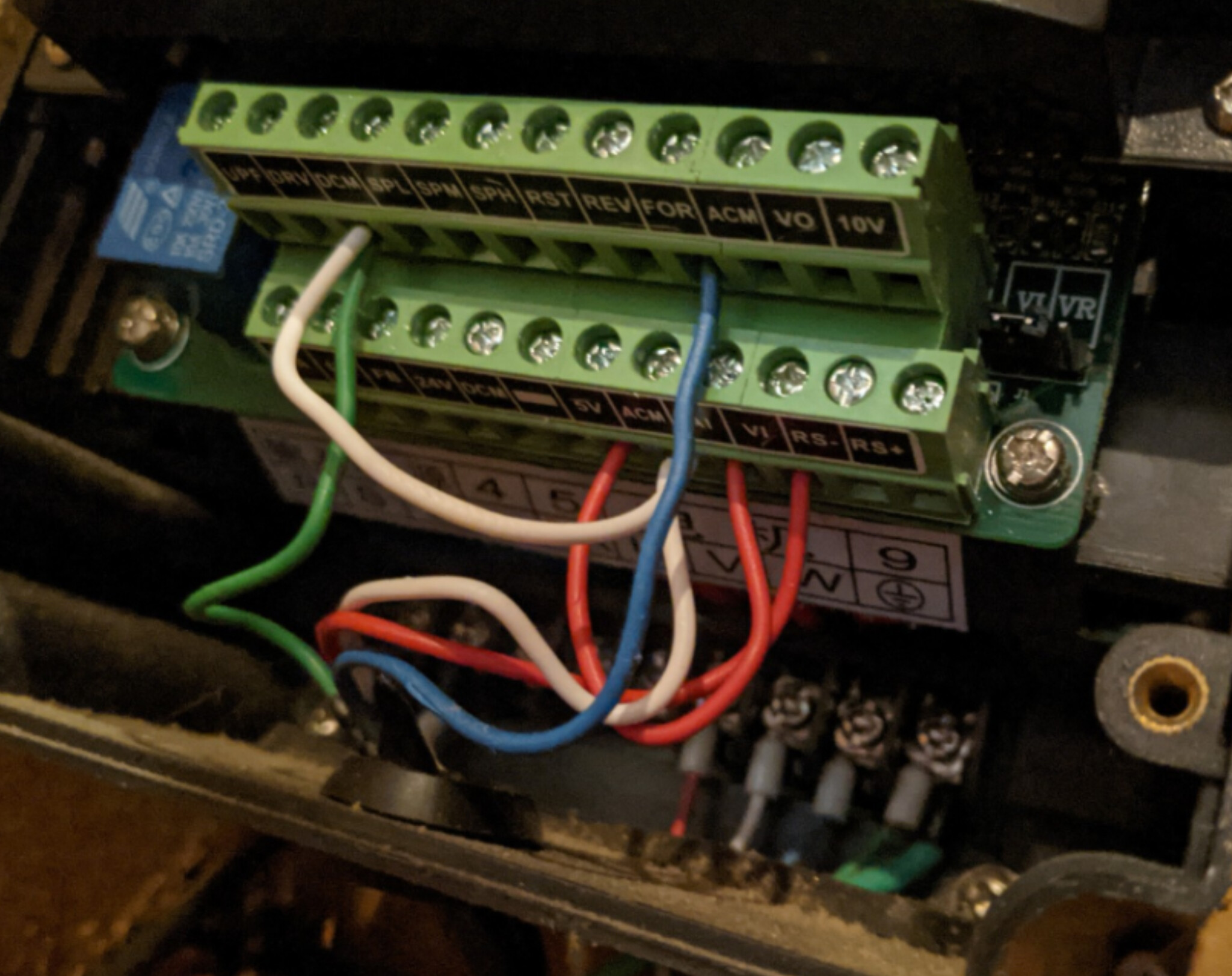
VFD Wiring:
LongBoard SpinPWM (red wire) ![]() VFD VI (longboard sends 0-5vDC to the VFD input)
VFD VI (longboard sends 0-5vDC to the VFD input)
LongBoard SpinPWM Ground (white wire) ![]() VFD ACM (Analog variable input ground)
VFD ACM (Analog variable input ground)
LongBoard Coolant (blue wire) ![]() VFD FOR (digital input to turn on the spindle in only one direction, for me forward, set in the VFD settings) 5vDC triggers spindle always on, but SpinPWM is what sets RPM.
VFD FOR (digital input to turn on the spindle in only one direction, for me forward, set in the VFD settings) 5vDC triggers spindle always on, but SpinPWM is what sets RPM.
LongBoard Coolant Ground (green wire) ![]() VFD DCM (on or off digital signal circuit. For my setup it’s always triggered on)
VFD DCM (on or off digital signal circuit. For my setup it’s always triggered on)
Now the tricky part. Without the below wiring I could not get the spindle to zero out the spindle RPM. This is where an electrical engineer or subject matter expert would explain the circuits…I just tinkered until it did what I wanted.
Short (red) wire from VFD 5vDC to AI
Short (white) wire from VFD ACM to DCM
I’m probably way off here, but my thought is that the Analog input needed a 5vDC signal to measure the 5vDC input from the LongBoard. The tied grounds nulled out extraneous voltage. Without the ACM to DCM tie, I could not get the Spindle to zero out with a S0 gCode line. Hopefully someone can chime in and tell me why that works. I’ve been running my machine for over a year like this and nothing has blown up yet.
3. GCode Post Processor / Software
At this point, you should be able to use gSender or UGS to turn the spindle on and off using the M3 command for On and M5 command for Off. You should also be able to use the S command with S0 being the off setting and s24000 being max RPM (spindle and VFD dependent). If you haven’t invested in a good multimeter I’d recommend it. Especially if you’re trouble shooting the circuits at this point.
Once that is working and verified you need to work on your post-processor. In Vectric Vcarve I edited the GBRL gCode Post Processor to include a header to each toolpath that will turn the spindle on with the associated spindle speed and then turn it off post completion and prior to the movement of the spindle to home:
±--------------------------------------------------
- Command output after the header to switch spindle on
±--------------------------------------------------
begin SPINDLE_ON
“[S]”
“M3”
“G4 P12”
[S] sends the projected Spindle speed to the LongBoard and out to the VFD as a fraction of the 5vDC signal. For example my 24,000 RPM = 5vDC, for 12,000 RPM the Longboard sends a 2.5vDC signal.
M3 starts the spindle. The P12 code pauses movement of the spindle for 12 seconds before initiating movement for the first cut. This allows the spindle to spin up to max speed prior to making a cut.
At the end of the program I have the following code:
“M5”
“G0 [ZH]”
“G0 [XH] [YH]”
“M2”
M5 shuts down the spindle before moving to home.
So hopefully that helps. If you have questions please feel free to post here or send me a private message.
1 Like
For those that are looking to run a 110V 1.5K water cooled 65mm spindle I have posted the installation instruction here. https://www.facebook.com/groups/mill.one/permalink/1149912342146762
1 Like
Blunderpunk,
The way my machine works through the long board is speed only. To turn the machine “off” the post processor adds a “S0” code to the M5 code, so the VFD stays on, but with no voltage applied to the spindle.
I had to set PD001 to “1” to accept the voltage change.
Hope that helps.