VFD Wiring Instructions

Hi team,

I was wondering if anyone would be willing to share VFD wiring instructions for the Long Mill controller.

Based on the image above, I’m guessing the 0-10v wire goes to the spindle speed contact. I just want to make sure the 24v power output can be wired to the board.

Thanks for the help!

Rob

Hi @Dudemeister, there are many different ways to wire a VFD. Normally the controller is looking for a signal which tells it which direction to spin, and another signal which tells it how quickly it should spin. I’m not sure which model VFD you have so I can’t confirm whether the diagram you’ve posted would be appropriate for your setup, would you be able to follow-up with some more info?

Hi Chris,

The image above is the same VFD I’m using and the same wiring (I pulled my old CNC Spindle and VFD for the Longmill). The 0-10V cable, ground and 24V power should be inputs from from the Longmill board to the VFD and the U,V,W wiring is going to my spindle.

Thanks

Could you provide the model #?

The LongMill controller was made to provide 0-5V for speed control, and toggle between 0 and 5V for the direction control, so I can’t be sure how this will apply to your specific VFD. With a VFD we tested on, this configuration worked, I just had to change the input voltage range from 0-10V to 0-5V so that the controller knew what to expect. Wiring and programming of these VFDs seem to be completely non-standard so it’s best that I provide information on a case-by-case basis.

It’s a 220V 1.5 KW Huanyang Model:

.

The Model # is HY01D523B.

Hey Chris,

Couple questions on the longboard and UGS that may help this:

  1. Can I wire the longboard SpinPwm directly to the VFD? I currently have it wired the following way:

Red wire: Longboard SpinPwm -> VFD VI terminal
White wire: Longboard SpinPwm Gnd -> VFD ACM terminal
Green wire: Longboard SpinDirection -> VFD FOR terminal
Blue wire: Longboard SpindDirection Gnd -> VFD DCM terminal


VFD Program Settings Specific to external commands:

  • Source of Run Commands: External
  • Source of Operating Frequency: External
  • Input Voltage Power: 5V
  • FORward: Turn Spindle ON from external Source
  1. Does UGS M03/M05 command send a power on signal to SpinPwm output? If so, I’m guessing it is a 5V signal at UGS max spindle RPM setting? I’ve set my spindle up on UGS for a max RPM of 24,000 but the votage on the SpinPwm seems to max out at 2.6volts.

  2. Spindle Direction command: how do I send a spindle Direction command to the longboard through UGS? I currently have that as my trigger for turning on the spindle with the FOR terminal, however using a multimeter there is no voltage coming from the Longboard terminal when I turn the spindle On/Off in UGS.

  3. Lastly, and maybe this is where I should have started, is there a wiring diagram / manual for the Longboard, or documentation on it’s integration with UGS?

Thanks for the help in advance.

Hi Rob,

As Chris mentioned, the LongBoard allows you to change the signal on the Spindle PWM output between 0-5V, as well as Spindle Direction.

The voltage on Spindle PWM will be in relation to the spindle speed you set and the maximum spindle speed. For example, if your max spindle speed set in the controller’s settings is 30,000, and you send the command M3 S15000, then the voltage would be set to 2.5V.

(set RPM) / (max RPM) x (5V) = output voltage

You can find how to change EEPROM settings to be able to change your max spindle speed here: https://sienci.com/dmx-longmill/changing-eeprom-settings/

Using M4 SXXXX command sets the speed as well but also activates the Spindle Direction pin to indicate the change in direction.

There are no wiring diagrams available for VFD wiring specifically for the LongMill. I would recommend contacting the manufacturer for additional support.

Andy,

I appreciate your help. I’m still having issues with the board pushing out any voltage greater that 2.5V. I’ve ensured the EEPROM settings are set to something greater that 24,000 just to test the voltage and I’m not able to reach 5V.

Below are my EEPROM settings:

This is with the M05 command or M03 S0 (Good to Go, no issues):

This is with the M03 command running the spindle at 12,000 RPM (should be close to 2.5V which it is):

This is with the M03 command running the spindle at 24,000 RPM (Anything over 12,000 RPM shows a decreasing voltage):

Also, when I run the M04 command I only receive a maximum voltage of 1.8V. Not a huge deal, but it doesn’t trigger a 5V current.

I’ve flashed the latest firmware and get the same output for both. I’m probably doing something really stupid. Any ideas?

Your multimeter is set to measure in AC voltage not DC voltage

Hi Rob, how’s your progress been on getting the VFD set up?

Chris,

I was able to figure out the wiring. I’m sure it’s not setup exactly like it should be, but so far it’s been working great. I’ll post the wiring diagram and VFD setup codes shortly. The RPM issue I was having before was an improper VFD code that I finally figured out.

I’m also using VCarve so I’ll share my post processor here as well. The one thing I haven’t figured out just yet is how to program a tool change into the post processor that works with UGS. Ultimately, I want to pause the program, shut the spindle down, move to a position to change the tool, zero the Z axis with the probe and then continue the program when I press the play/run button.

I’ll try to build a tutorial on the forum that can help with the VFD setup.

-Rob

1 Like

Rob, I’ve been checking out cncjs. One of its capabilities you might find useful is tool changes. Unlike UGS it accepts M06 commands and stops to allow the tool to be changed. The cncjs github site lists macros that allow initial tool height setting using the probe block, and a way to probe the block after a tool change to reset Z zero with the new tool, similar to the way Carbide Motion uses the BitSetter. cncjs now has a desktop version so you don’t have to go through the node.js installation.

1 Like

Bill,

This is great info. I’ll definitely need to try it. Thanks for reaching out.

Rob

@BillKorn Bill: Where can I find the desktop version? The only link that I can see on the page is over a year old, so I’m assuming that I am in the wrong place.

/github.com/cncjs/cncjs/releases

Scroll down about half way. You probably want this one:

https://github.com/cncjs/cncjs/releases/download/v1.9.22/cncjs-app-1.9.22-win-x64.exe

1 Like

Rob, can you share the details of your spindle - brand, model, source, etc. Although I think the Makita is an acceptable general use router, it doesn’t go slow enough to safely drill with regular HSS drills, and I’d like to reduce the noise without going to an enclosure.

Thanks.

Bill.

1 Like

Bill,

I bought a water-cooled 220 volt 1.5kw spindle/VFD combo from Amazon a couple years ago that was used on my old home-built and very imprecise CNC machine. The VFD and motor kit is model number HY01D523B, but from what I can tell most models are similar in setup. It’s an inexpensive Chinese product, but other than having a little guilt for not buying a US product, I’ve been very happy with the way it works on the LongMill. I think the max collet size is 3/8", so no 1/2" bits.

Link to the product (no longer available - but plenty of other options are): https://www.amazon.com/gp/product/B01M4I7YHQ/ref=ppx_yo_dt_b_search_asin_title?ie=UTF8&psc=1

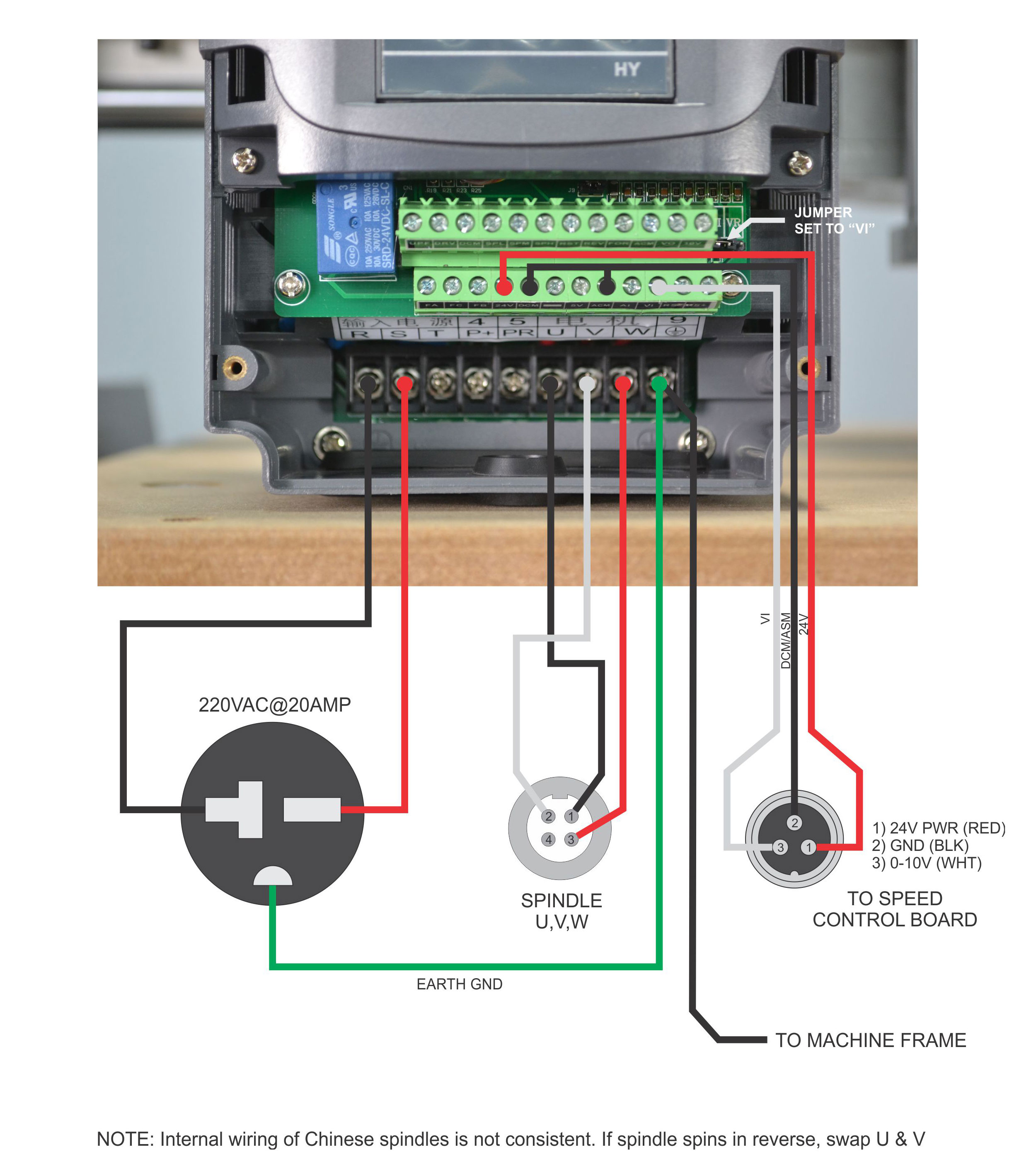
The most difficult part of the setup was figuring out the wiring from the LongMill board to the VFD and the VFD programming codes.

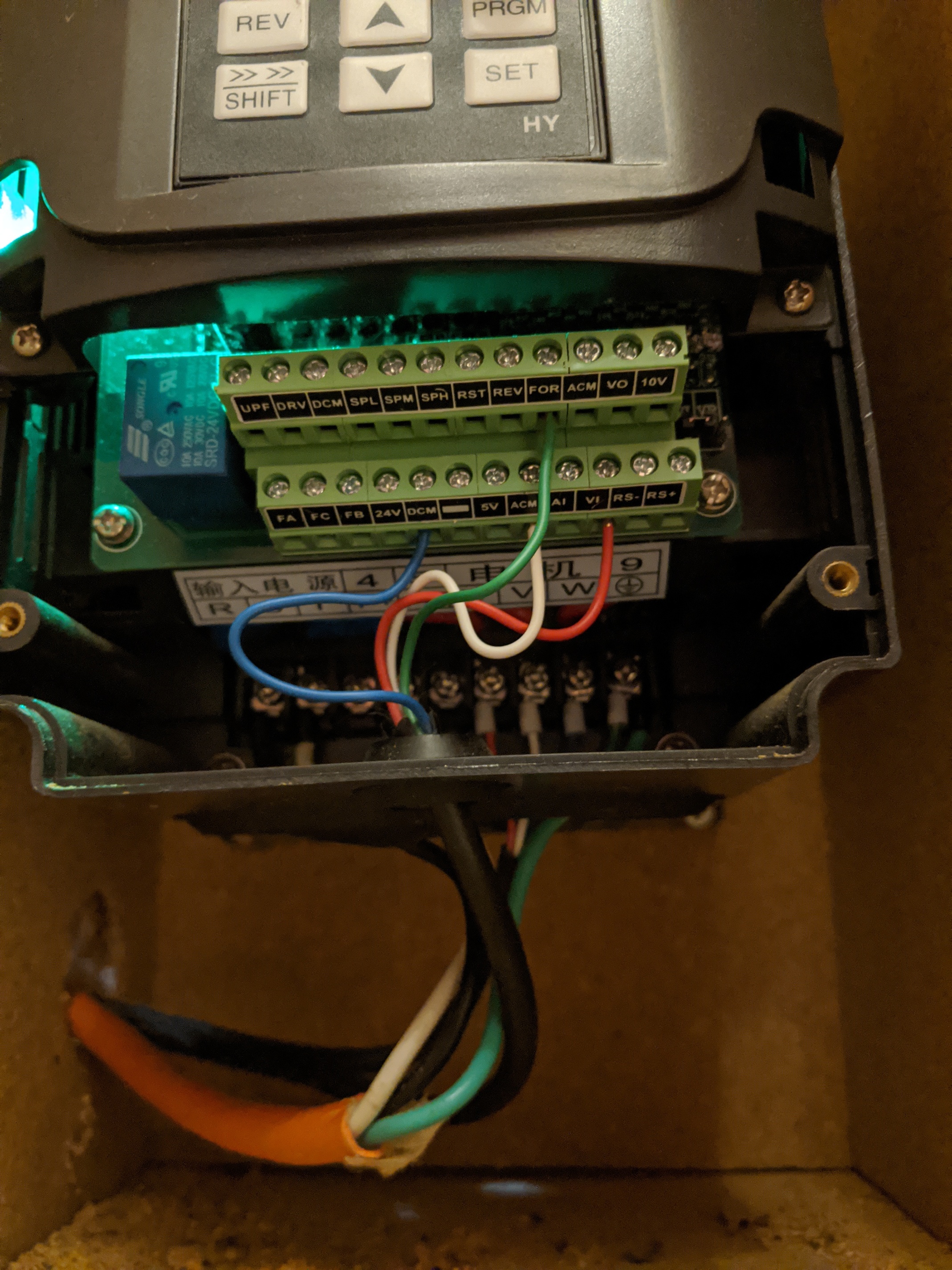
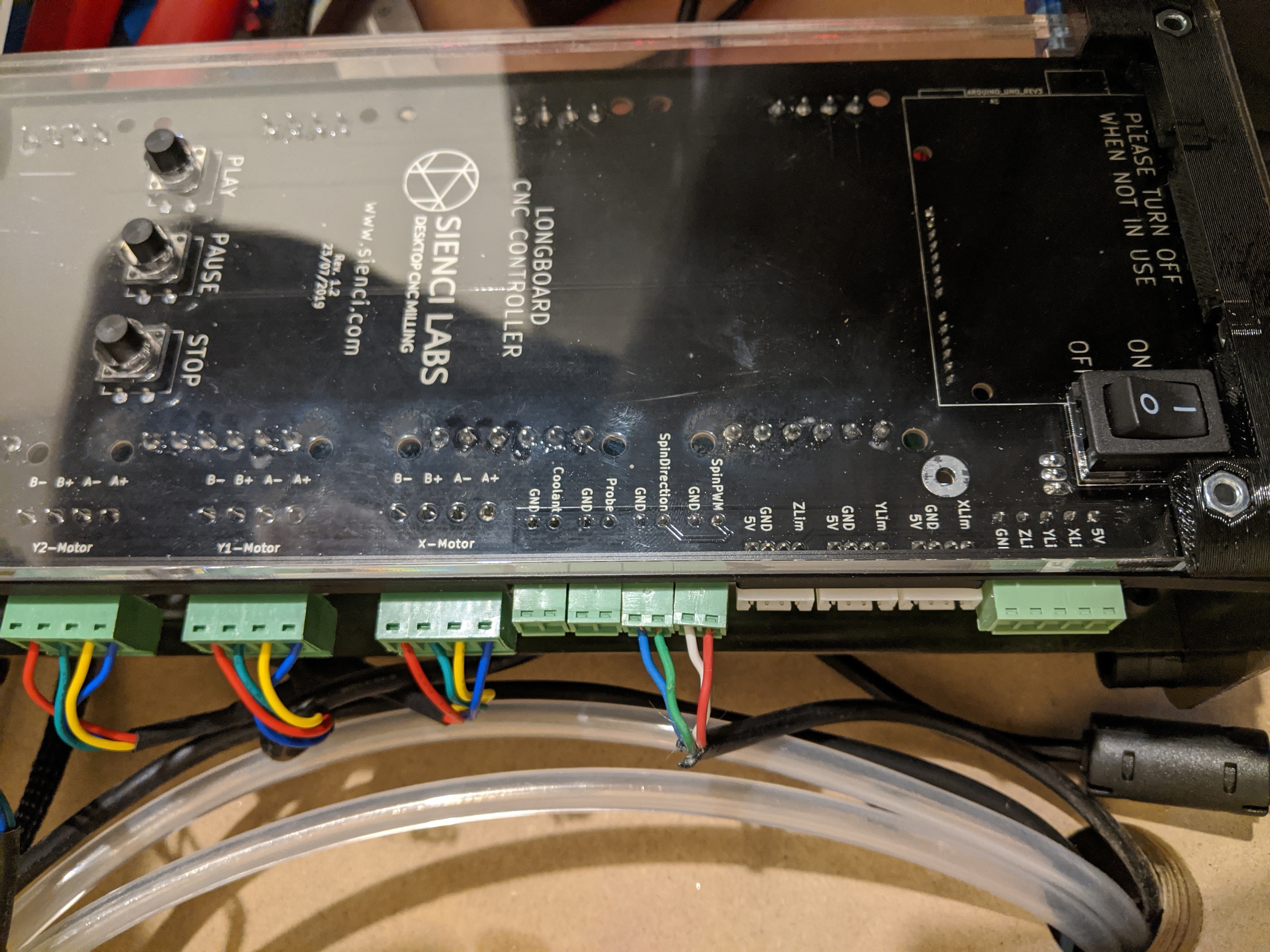
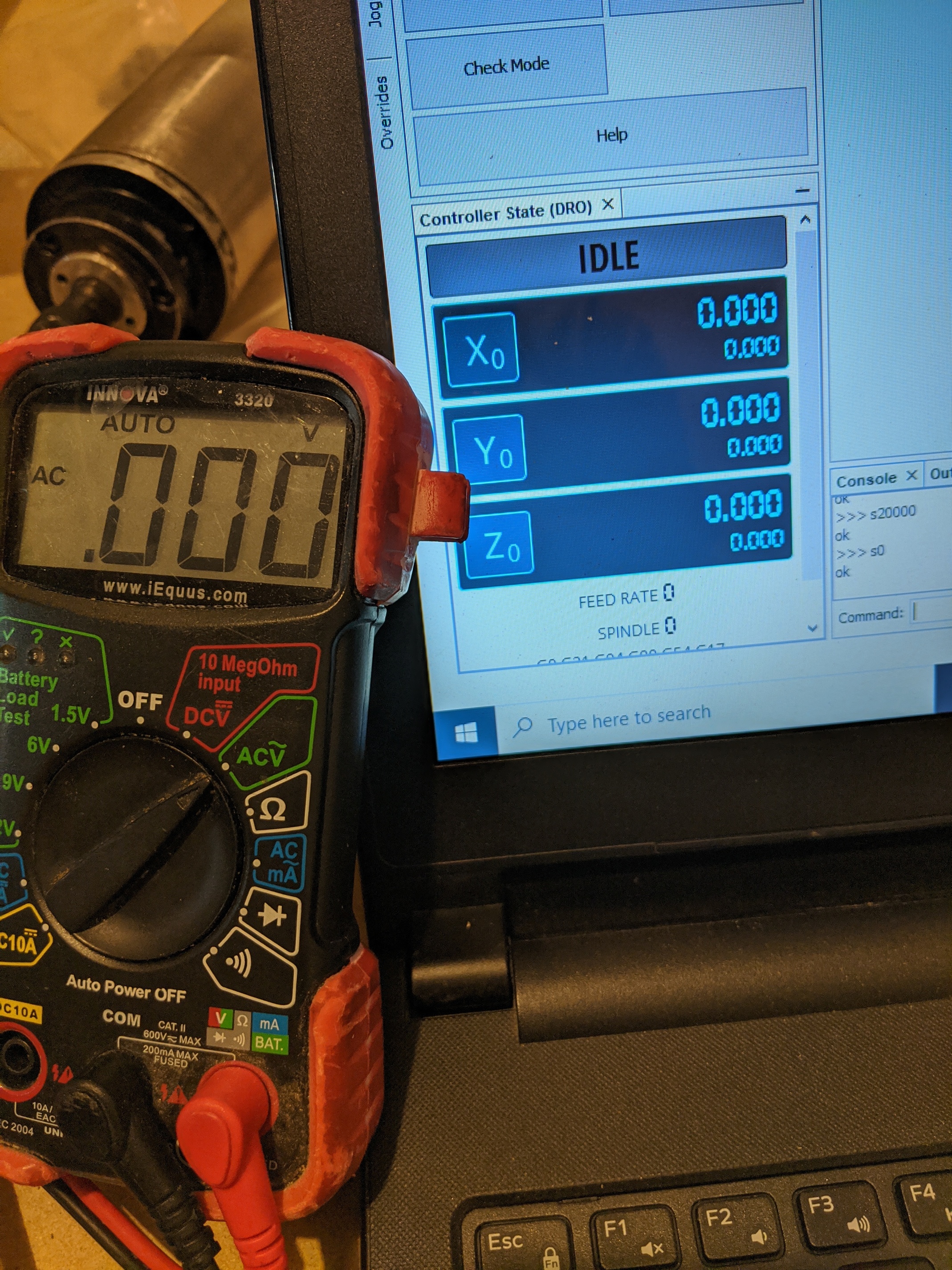
For the wiring you’ll need to run the Spindle PWM to the “VI” (Voltage Input for the potentiometer) input on the VFD and the GND to the “ACM” (analog ground) on the VFD. I would think this is the only thing you need to do from the LongMill board to the VFD, but I could not get the VFD to go to a 0 RPM when the M5 code was applied. It would go to ~100 RPM, and obviously that’s not acceptable. So after a lot (i mean a lot) of tinkering, I was ran another wire from the LongBoard Coolant output to the “FOR” (forward rotation) input on the VFD and the Coolant GND to the “DCM” (digital ground - which i believe makes it a simple on/off switch for the spindle commands).

VFD program codes are below. I’ve added the Code number and the function just in case it doesn’t necessarily match up with other models:

PD013 (Reset) - 8 (do this first if you are using a previously programmed VFD and need to factory reset the codes)

PD001 (Source of Run Commands) - 1 (External commands, i.e. Longmill Board)
PD002 (Source of Operating Frequency) - 1 (External Terminal)
PD003 (Main Frequency) - 400 (Motor dependent)
PD004 (Base Frequency) - 400 (Motor dependent)
PD005 (Max Operating Frequency) - 400 (Motor dependent)
PD006 (Intermediate Frequency) - 2.5
PD007 (Min Frequency) - .2
PD008 (Max Voltage) - 220 (Motor dependent)
PD009 (Intermediate Voltage) - 15 (Motor dependent)
PD010 (Min Voltage) - 8 (Motor dependent)
PD011 (Frequency Lower Limit) - 120
PD014 (Motor Acceleration Time) - 10 seconds (this becomes important when setting your GCode delay after M3 command
PD015 (Motor Deceleration Time) - 10 seconds
PD041 (Carrier Frequency) - 8 (Motor Dependent)
PD044 (Forward Function tied to the FOR digital input discussed above) - 2 (Forward rotation when VI received Spindle PWM input > 0 volts)
PD70 (Analog Input - VI Input) - 1 (5VDC which is what the Longboard Spindle PWM outputs)
PD141 (Rated Motor Voltage) - 220
PD142 (Rated Motor Current) - 5
PD143 (Number of Poles) - 2
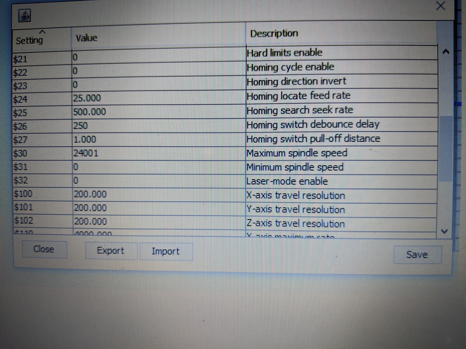
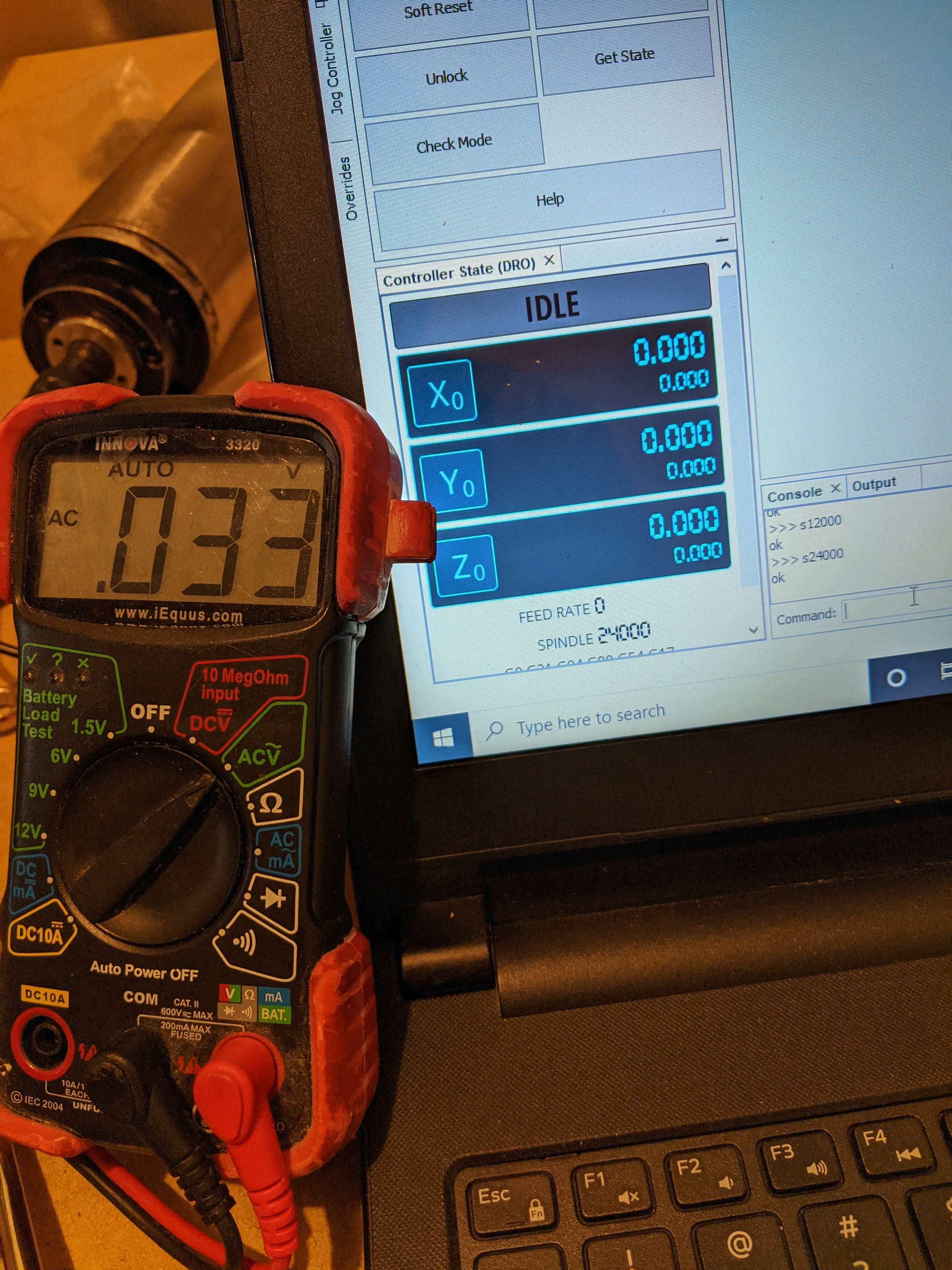
PD144 (Rated Motor Revolution)- 3000 (this equated a 5V input from the Spindle PWM to 24,000 RPM)

I’m not sure what CAD/CAM software you’re using, but with VCarve I had to go into the GBRL mm post-processor and add the following to the Spindle On command:

±--------------------------------------------------

  • Command output after the header to switch spindle on
    ±--------------------------------------------------

begin SPINDLE_ON

“[S]”
“M3”
“G4 P12”

…and the following to the end of file command:
±--------------------------------------------------

  • Commands output at the end of the file
    ±--------------------------------------------------

begin FOOTER

“M5”
“G0 [ZH]”
“G0 [XH] [YH]”
“M2”

After that I could trigger the spindle on and off with the M3/M5 commands and set spindle speed using SXXXX. I’ll give the M6 command a try with CNCJS when I get back to hobby time.

Hope that helps. I’ll try to make a better tutorial with pictures in a couple weeks.

3 Likes

This is awesome info. Thanks for taking the time to explain in detail.

Bill

Bill,

Long time since the last post. I’m finally getting around to using my machine again and I’m ready to try CNCjs. Do you mind sharing some of your settings such as the probe command? I’m using the sienci probe if that matches with your setup.

Thanks for your time.

Rob