A big reason for my acquisition of a CNC router is being able to cut accurate panels for cabinetry.
I have played a bunch with my new toy and am starting to get a bit more confident. I am now trying my luck at building small boxes. What I learn at this stage will be used for making drawers and stuff.
I am not having much luck with my joints.
The material I am cutting is particle board, 13 mm thick. Each one of the stair steps is 4.333 mm on each side in the CAD model but in real life there is a significant difference in the height of the steps. What I expect is a tight fitting joint but what I get is anything but …
I was thinking that maybe my stock wasn’t lying flat so I used double sided tape on the back side where the stair steps are hoping that any bow would be taken out by the double sided tape.
Well, there is no difference in the end result - the joints still fit like crap (
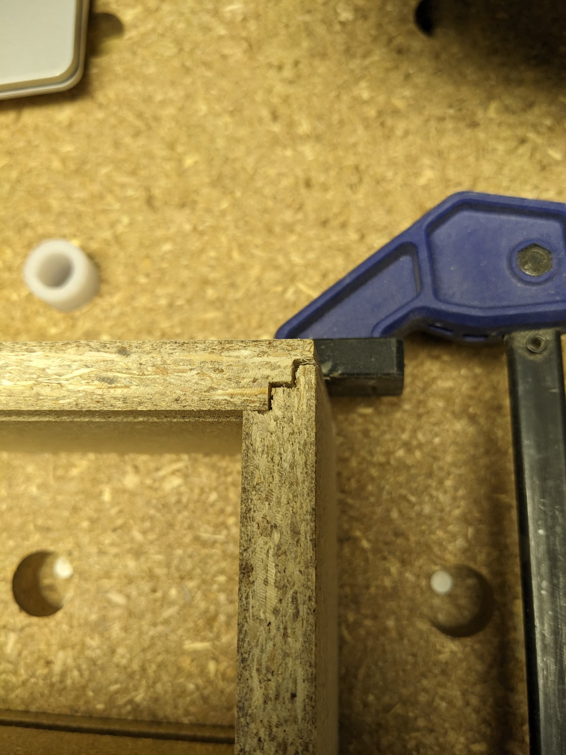
Measuring the stair steps against one outside edge (they are supposed to be 4.33 mm each) I get readings of 3.9,7.8 and 12.8 mm making the steps 3.9, 3.9 and 5 mm. Note that I have the material set at 13 mm in the CAD program so the 12.8 is slightly out but not enough (IMHO) to cause significant error.
I use the spoil board as my zero z reference and while there are minor deviations in the sliver of material left over on the root of the through cuts, we are talking maybe 0.1 or 0.2 mm.
My test box is only 10020080mm tall - I shudder to think what the corner joint will look like when I get to real life sized objects.
I have run out of ideas what I should check for. I suspect there is some very basic fundamental mistake I am making and it is likely staring me in my face … but I just can’t see it. A fresh set of eyes is called for.
Added: Z=0 was measured with the auto zero probe but I confirmed the hight with the paper method. I get a z reading of +0.14 mm when I have a slight resistance pulling out the paper and the paper is between 0.10 and 0.11 thick.
@Jens With respect, if you are going to use junk material, you will get junk results.
Also, you will never get tight joints with the method that it appears you are using. It appears that you are trying to get square corners with a bit that is cylindrical. It can’t be done. If I have misread your process from the pics you have posted, my conclusions may well be wrong. This is simply MHO.
Looking at the pictures, it seems you have a systematic error of some sort. Even with good material (and I understand you are likely trying with not so good material first) it can be really tricky to get precise results in a joint like that with imprecise materials.
I have experimented with making some cabinet boxes (and have been making good progress with it). The key is that you have to ensure you are always mating either cut surfaces, or reference surfaces. One of the issues you will see is that errors are compounding - in this case, doubled by any inaccuracies.
To make the fit work, you will have to use the TOP of the long pieces as a reference surface (that is, use its top surface as your zero) and use the BOTTOM of the short pieces as your reference surface (that is, use its bottom surface as your zero).
This will ensure that any error due to material deviations lands in non-critical dimensions - projecting into the box for the short pieces, and projecting out of the box for the long pieces. This way all mating surfaces are known dimensions and distances apart from each other.
Let me know if that explanation and resolution makes sense. That should tighten things up dramatically. The other thing you will have to do is ensure you eliminate any other sources of variability - machine squareness, wasteboard surface level, etc.
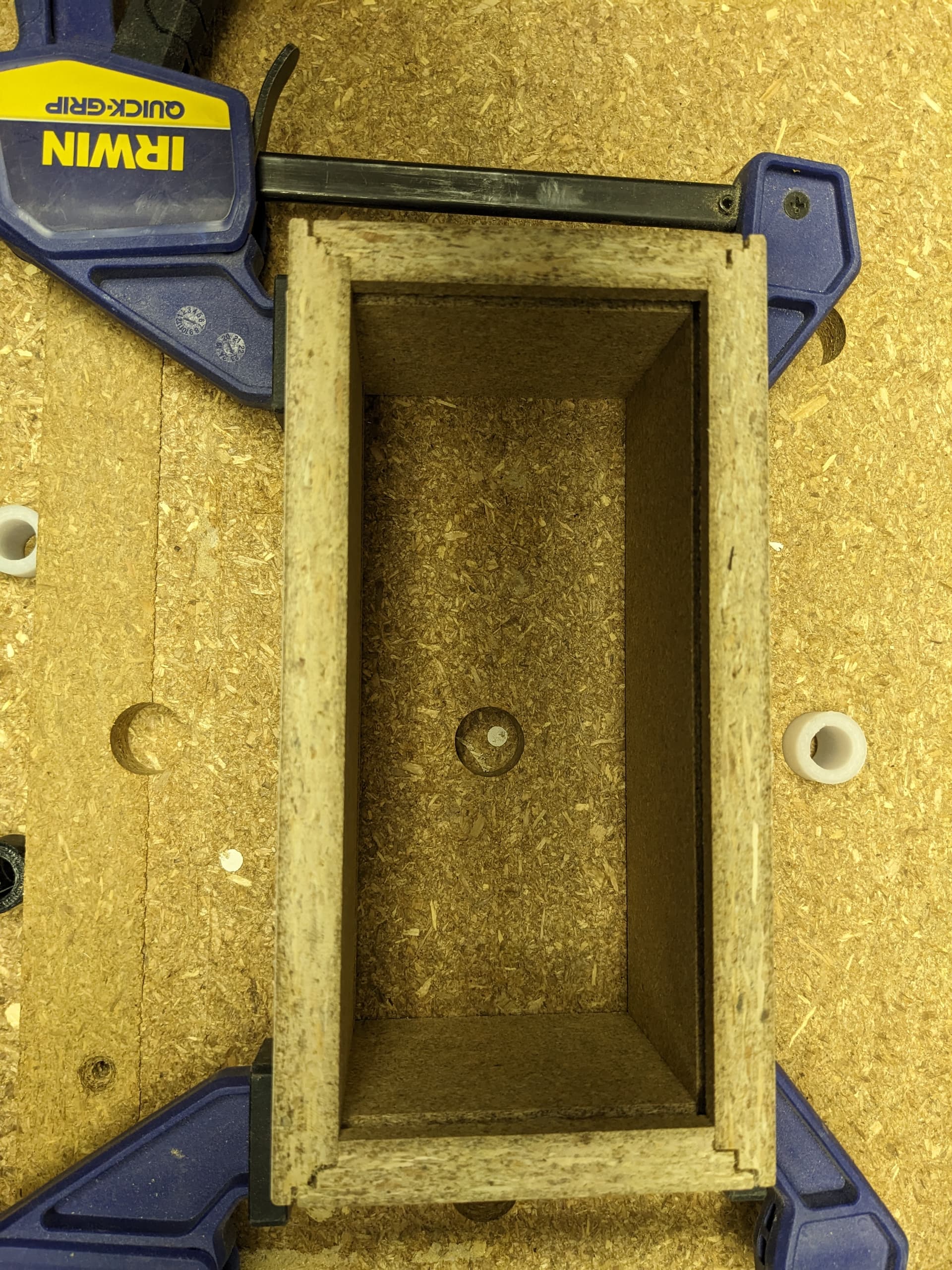
There are 4 pieces, two short, 2 long to form walls of a box. There is a slot on one side that would hold the bottom of the box.
Looking at the cuts, the slot for the bottom is cut too deep (but it doesn’t affect anything). The stair steps for the corners is what I was trying to describe. There are three steps. They should be 4.33 mm, 8.66 and 13 mm tall. The biggest problem is the first step from 13 mm to 8.66 mm which in real life is a step from 12.8 mm to 7.8 mm which is about one mm too deep. So the two lower steps are about the same size at 3.9 mm but then the first step is 5 mm which is way too large and which throws everything off.
Hopefully this makes a bit more sense now.
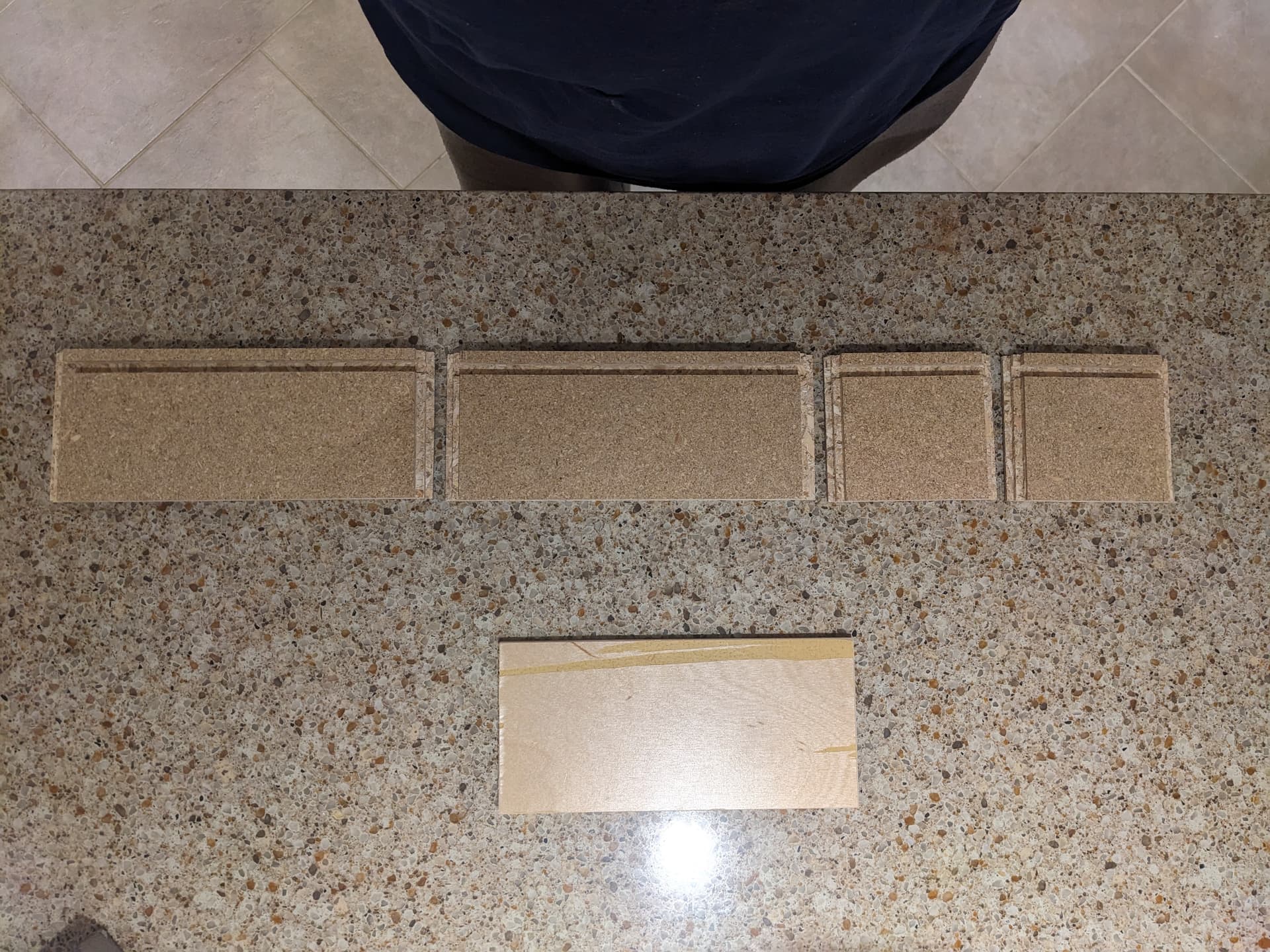
Milling is done with all for pieces in a single line.
BTW, I have verified that the spoil board appears to be flat. I also brought the bit up to 25.4 mm and used a 1 in gauge block to confirm that when the mill thinks it is at one inch high it is in fact at one inch above the spoil board
My next thing to check is to try and look at the gcode. I verified the model but I don’t know if the gcode reflects the model or if something weird is happening during post processing.
@elbarsal, I agree I have a systemic problem. I do not understand what you are trying to say about changing the reference (z=0) position to top and bottom of the stock piece. I will have to try and digest what you are trying to say.
Since I obviously didn’t properly describe my problem, let me add that the raw stock is a single board. All 4 pieces are cut at the same time from this single piece of stock.
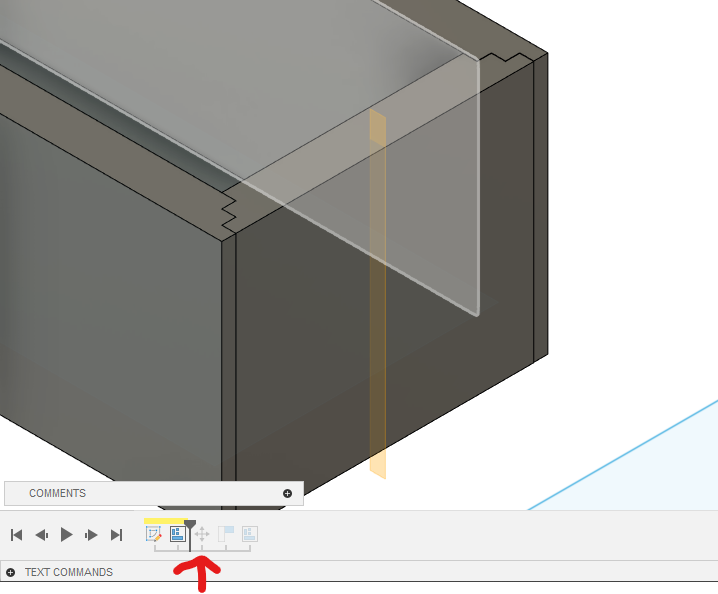
Here is another picture to clarify how things were milled. There were two setups - one for the bottom of the box (the piece at the top) and the second for all 4 walls. They were milled exactly as shown in the picture.
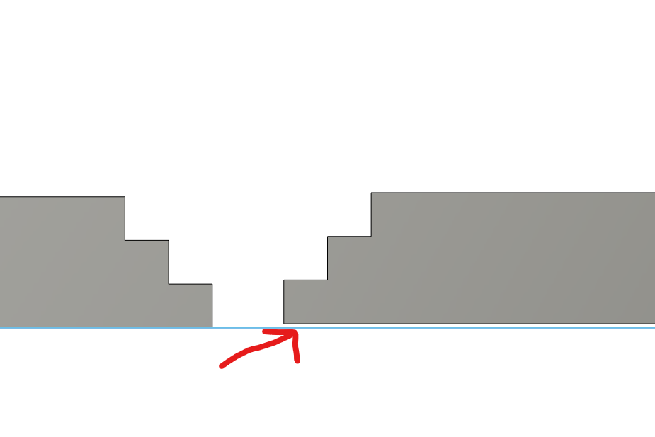
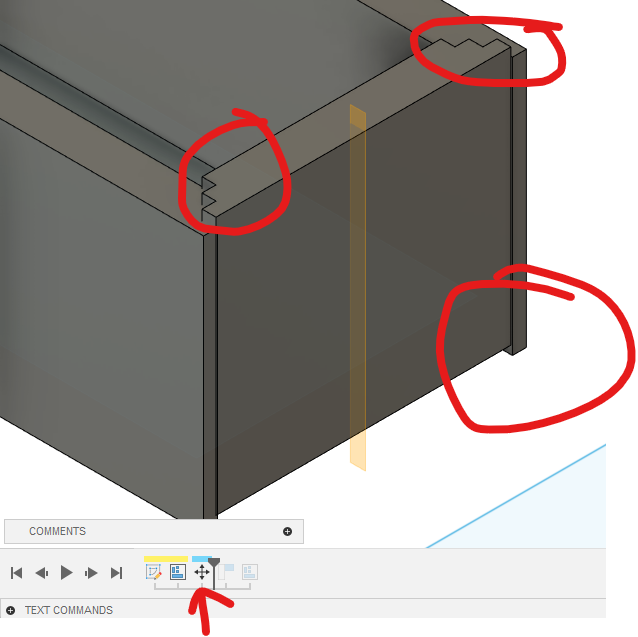
@Jens - consider your lower right corner in the second picture with the clamps:
For the bottom piece, set the Z zero to the spoil board. This will ensure that each critical step height (call them step 1 and step 2) are exactly the heights you expect. The width will of course be exactly what you expect. Step 3 is the stock surface - and where that lands isn’t critical.
For the right piece, set the Z zero to the top of the stock. This will ensure that the distance from the inside of box (top of the stock) to each step exactly matches what you cut into the bottom piece.
If you exaggerate the material thickness errors, you can see how this removes inaccuracies. Imagine the bottom piece is very out of spec (double thickness, even) - the extra thickness is unconstrained by any joint or mating surface - it just ends up inside the box. Think of the right piece as double thickness, and you see the same thing - the extra thickness just extends off to the right, so it doesn’t affect any mating surfaces.
Obviously material thickness errors are generally much smaller, but they unfortunately do add up. It’s important to move the errors to surfaces where they don’t matter.
Quick edit - of course, the mirror pieces require the same zeros as their mates.
My gut tells me the issue is a Fusion360 issue. I will have to do a deep dive into that with maybe a bunch of sample cuts and then see what mill produces. There are several things in relation to the cutting heights that don’t make sense to me. Chances are that I screwed up something in the ‘manufacture’ section where all the tool paths are set up.
I exported the file and this is the result. It is a .f3z file which is not directly supported so I renamed it as a .txt file for the upload. You will need to change the extension back to ‘.frz’
I found one thing in Fusion that I can’t explain …
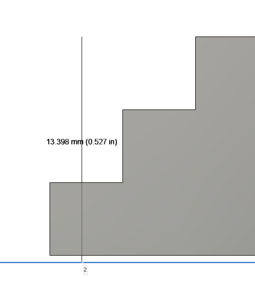
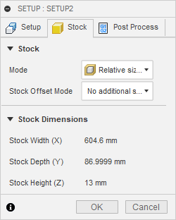
I designed the box with 13mm thick side walls. I then ‘arranged’ the 4 sides flat for machining. Well, for reasons that are above my pay grade, in the ‘setup’, fusion reports a stock height of 13.398 mm. I have zero idea where the extra 0.4 mm is coming from. The four pieces are 13 mm thick/tall and there is nothing higher than those pieces. There is no stock added in the stock setup.
When I ran a detailed simulation and looked at the displayed data, the cutting heights were wrong - most likely related to the wrong stock size
I made a practice model and all the dimensions shown were as expected and the cutting path was at the heights specified.
Wow, good catch !!! I don’t understand how I managed to offset the pieces - it is an automatic process performed by Fusion with the ‘arrange’ command.
Could you elaborate on how to use the ‘align’ tool please? Nevermind, I see that you included a tutorial which I didn’t catch right away.
Got it sorted and will do another milling run tomorrow to see if this solves my issues.
Thank you VERY much - I would have never found this without your help!
If you can give me a hint on how I managed to misalign things, I would appreciate it … but even if there is no obvious reason, at least I now know what to look for and how to fix it.
Added:
With the offset fixed, when I run the simulation, the cutting heights seem to be right on! I am looking forward to tomorrow’s actual milling run.
I didn’t see it at first because the flip happened in the design, not in the manufacturing model bodies (which are linked to the design bodies) See edit above.