Z axis probe... Something not right?

Running 1.3.2. Edge of Gsender. Also tried it on 1.3.5.

Followed the instruction for the chess piece in the you.tube video and the walk through on the “first project” on the webpage.

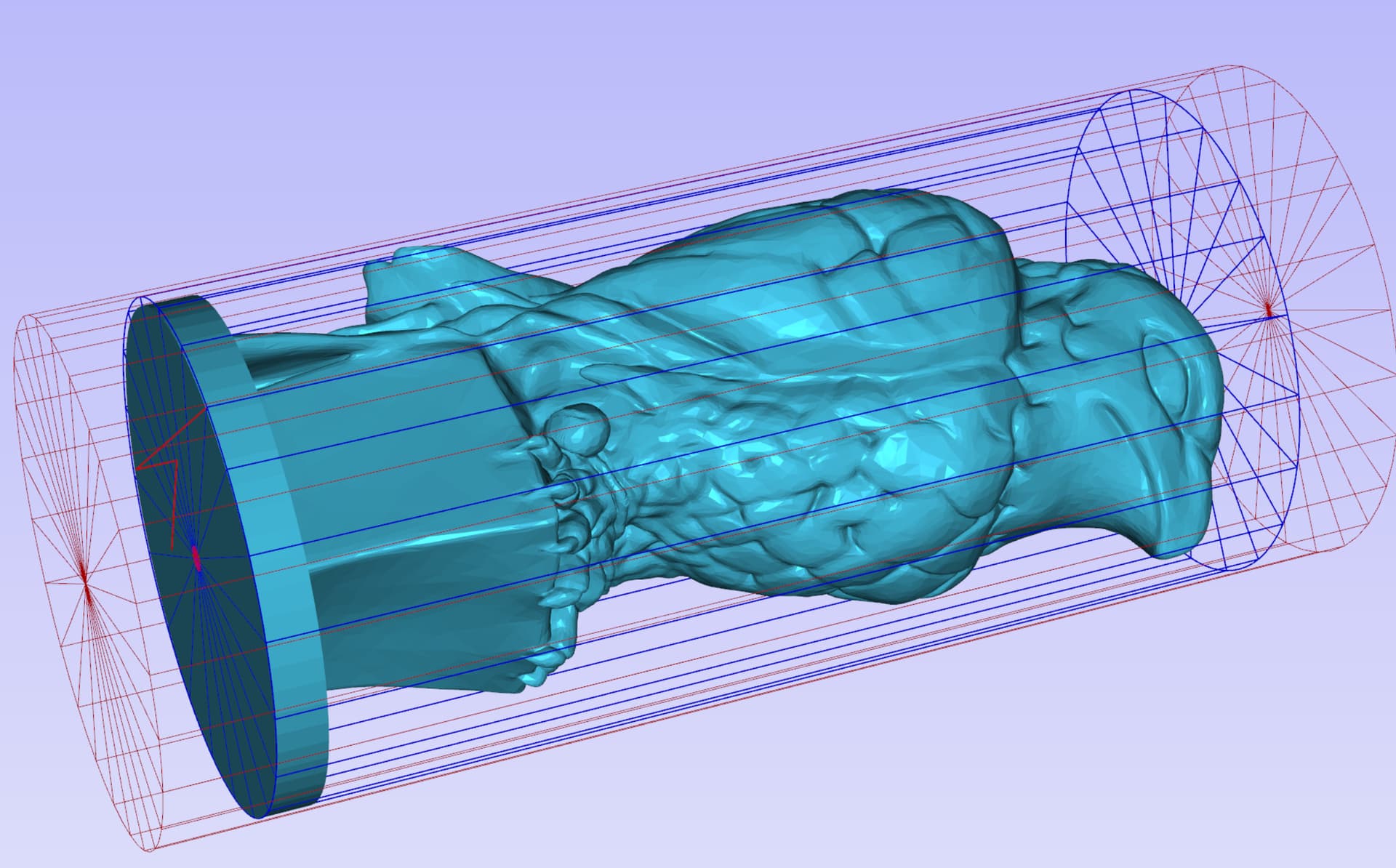
I used a different model of thingiverse - the maltese falcon.

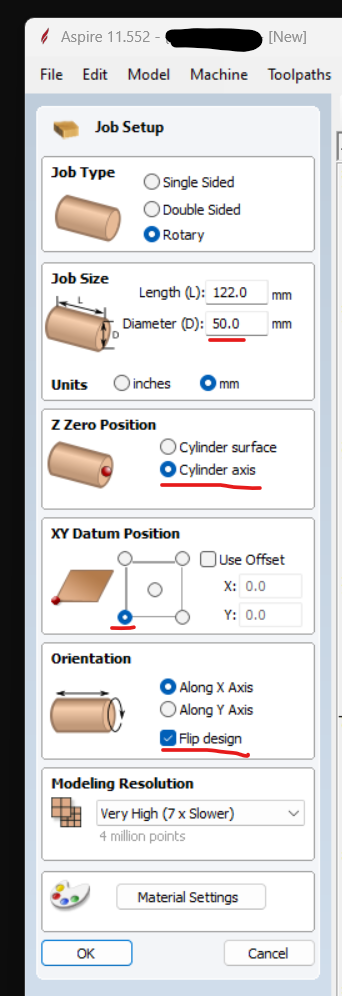
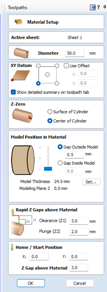
I have a license for Aspire. Stock I am using is 50 mm dowel.

Set the model to the boundry -1mm. Created the G code with the rotary vortex post processor. It seemed to me that when I ran the tool path in Aspire that it wanted to start at zero (center bottom) of the model and sprial out from the base, which would plung the bit to center and literally cut through the base, right at the start. Which it did but I’ll get to that later. Not sure how to prevent this in Aspire 11. Does that make sense?

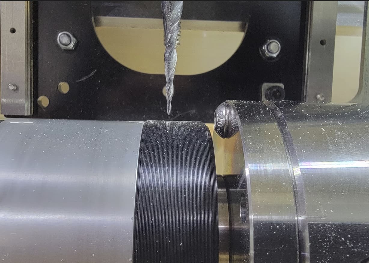
Ran the Z probe. One thing I noted different is that after the Z probe that Daniel did on the video, he just jogged the bit over the chuck on the x axis. I can’t do that because the bit will hit the chuck. There isn’t enought clearance. So, I raised Z and jogged X + (right) until I thought I had enough clearance from the chuck teeth to the bit. Which I did. Imported the GCode. All looked well. It was cylindrical. OK, check-a, check-a, check-a, let’s go!!

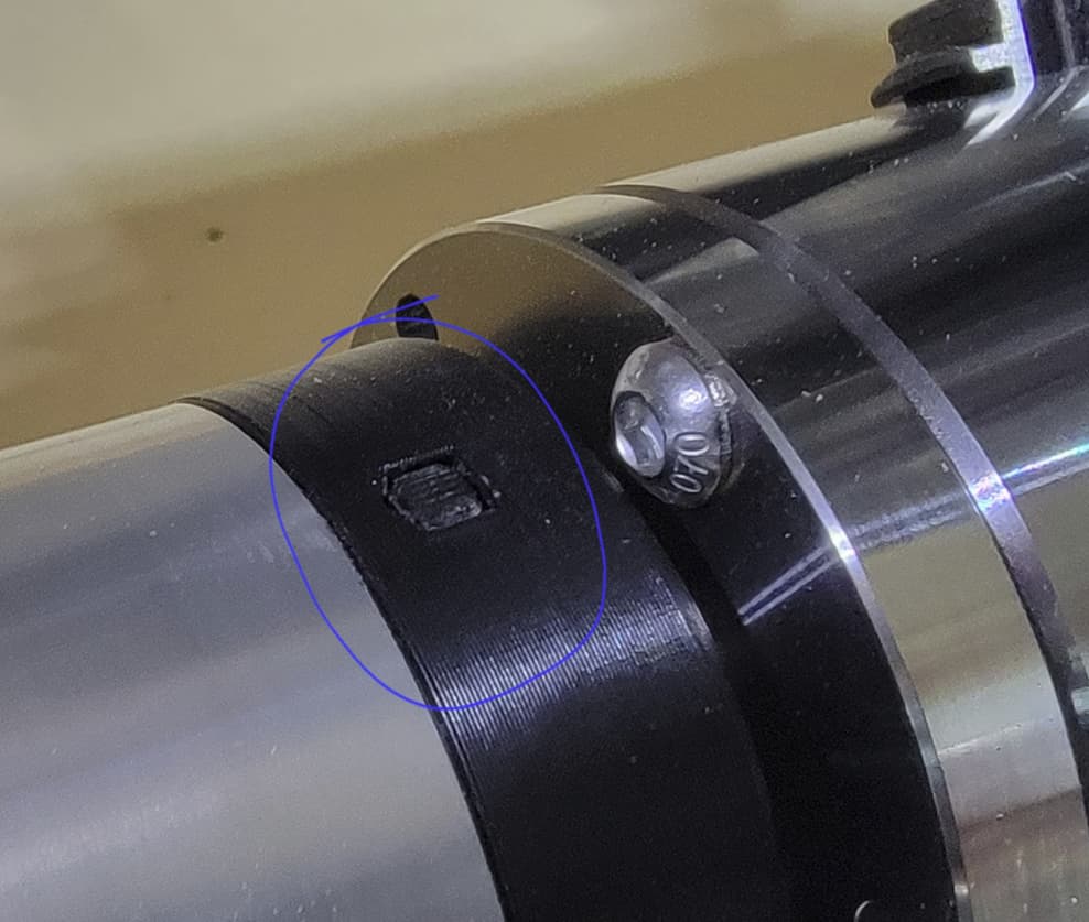
Z was probed, X was lined up, all looked good. Watched the video again. Started the router and it moved like 10 mm to the right and freaking PLUNGED right down to center axis — PaNiC bUtToN! but not before my makita collet screw ground into the f’ing teeth of the rotary chuck. Tis but a scratch!?? I guess I have some “personality now” on the rotary?! :stuck_out_tongue:

Anyway, I figured it was the setup as I suspected in Aspire that wanted to start at the center of the base… Again, not sure how to prevent this. So, I did what any hack amateur CnC operator did… I kept the panic button depressed and ran a “simulation” in GSender by “starting at line xxxxx” of the gcode until I got past that part. UGH. Hack work around, I know. Whatever. :stuck_out_tongue:

OK, I aligned it all again. Z probe, figured out that if I move X right +104, if it plunged again, at least the collet tightner nut wouldn’t freaking slam into the chuck teeth again. Pressed Start Job…

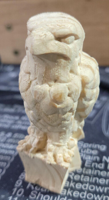
Keep in mind the base that I “added” was 50mm wide, the same width as my stock. the bit still freaking plunged 10 mm deep into the wood when it should have just been skimming the top of the stock. Stopped the job and tried it like 5 more times. Bit still plunged 10 mm into the stock. I am going mad. So I did some quick math - which I suck at but it’s not physics or anything. F’d around with it by jogging it to the right past the stock holder and trying to find center axis of the red dohicky. hit “Z” center and the raised Z and homed back to X. started the job from line xxxx again, a little short… Next try, a little deep. Then I found the perfect center and it’s runnind and looking great.

So, not sure what’s going on here. It’s digging about 10mm deeper when following all the protocols. using MM in Aspire, and using mm in Gsender. Wait… is the PP MM or inches? Maybe there is a problem there? I’ll have to check because you did the tutorials in inches… Hummm…

Still would like to know how to keep the model trying to start from the bottom center of the base in Aspire without my hack work around. The crew didn’t seem to have that problem with the chess piece.

Any help would be appreciated. A bit frustrated starting out. Thought I had it all figured out. 90 min later I have a chuck tooth with personality and almost broke a 50 dollar tapered bit. LOL.

Thanks very much-Lutra

I don’t have Aspire. Otherwise, I would ask you to post your file. I have VCarvePro.

I do have some questions, though. The answers may help fix things.

In Aspire

  1. When you say that you “set the model to the boundary -1mm”, what do you mean? Do you mean that you set the machining toolpath to the model boundary with a 1mm offset?

  2. In your material setup, where did you set the Z Zero Position? If you are following the Sienci tutorial, it should be set to cylinder axis.

  3. Where did you set the XY datum position? Again, if you are following the Sienci tutorial, it should be set to bottom left corner with no offset.

  4. Finally, I assume that you have the orientation set to along X Axis and flip design is checked. Yes?

  5. In the Toolpaths window, in Material Setup, where have you positioned the model in the material?

  6. Same window, what are your rapid Z gaps above material set to?

OK, now to gSender

  1. When you say that, after probing Z, you cannot jog in X because the bit will hit the chuck, do you mean that it will hit the jaws? After probing for Z0, the bit should end up just above the body of the chuck. If you are hitting the jaws, rotate the chuck.

  2. When you did jog in X, you jogged to where you set the X0 datum in Aspire, yes? That should have been on the left end, clear of the chuck jaws.

  3. Once there, you clicked on set X0 in gSender, yes?

The vortex post processor is in MM, but it does not matter. I design in inches in VCarvePro, because I am old and set in my ways. I’ve always run gSender in MM because I am a sadist, too. I also use the grbl mm post for flat work. It makes no difference at all.

1 Like

Thank you for responding again @gwilki . :slight_smile:

I’ll do my best to answer.

For questions 2 / 3 / 4, a picture is worth all the words :smile:

Yes, other then the model, I followed the instructions on the Chess piece video.

Here is the model and Gcode: Maltese Falcon Final.zip (2.8 MB)

  1. When you say that you “set the model to the boundary -1mm”, what do you mean? Do you mean that you set the machining toolpath to the model boundary with a 1mm offset?

    I imported the model into Aspire and it asked me to transform it:

    Step 1 - after import settings:
    image

    Step 2 - Scale Model to fit Material:
    image

    Step 3 - Set model diameter to -1mm from boundry
    image

    Model looks like this:

    Note the gap at the top and the bottom. I know that my model size is smaller than my material size but I don’t want to run out of room. My thinking was that I don’t want to bump the chuck teeth, or on the opposite side, hit the end stop.

    Also note that this wasn’t shown or discussed in the video. As I was reading through the website
    resource for Vortex Rotary on the Sienci page, I see that in “Your Second Project” they talk about 3D
    tabs. I could have prevented it from plunging all the way to center if I had read the entire way through.
    RTFMx2!

  2. In the Toolpaths window, in Material Setup, where have you positioned the model in the material?

  3. Same window, what are your rapid Z gaps above material set to?

    This is where I probably screwed up and why it seemed that my Z height seemed to be 10mm into the model even though I had the correct material dimensions set up?

    Not sure how to manipulate a model for rotary:

OK, now to gSender

  1. When you say that, after probing Z, you cannot jog in X because the bit will hit the chuck, do you mean that it will hit the jaws? After probing for Z0, the bit should end up just above the body of the chuck. If you are hitting the jaws, rotate the chuck.


Here is a pic after I probe Z. It’s just a couple MM above the screw the tip of the bit touched. This is before I loaded any G-Code at all. Just getting the machine set up. As you can see here, the bit is way too low to jog X right because it would hit the actual chuck. Is there a setting in GSender that I am missing?

  1. When you did jog in X, you jogged to where you set the X0 datum in Aspire, yes? That should have been on the left end, clear of the chuck jaws.
  2. Once there, you clicked on set X0 in gSender, yes?

Yes. I essentially went an bit past the chuck and hit X0 at that point.

I think my issues come down to:

  • Setting the correct Z height in Aspire?
  • Maybe missing a setting for Z-Height Probe in GSender?
  • Not knowing how to use 3D tabs for the gaps in my wood to prevent start plunges. :frowning:

End result was still pretty nice!!! :slight_smile:

Thanks again for your help. Would appreciate any advice for a rotarty newb.

-Lutra / Walt

@Lutraphobia I’m just heading out for a few hours and I’ll repond more fully on my return.

However, real quick. How are probing for Z0? You should be on top of the chuck. In the pic, you seem to be on the headstock somewhere.

1 Like

Yup.

I suppose NOT using the chuck to Set Zero is one of the more dumber things I’ve done with this machine.

There is a exposed screw head that I used to set zero. I have no idea what I was thinking. Watched the quick start guide and confirmed that you need to use the chuck to set zero. That is likely the issue here.

Updated pic of the exposed screw head:


Sorta seemed natural to use it :person_shrugging:

I’ll get another project going later and confirm.

I hope me being a complete numbskull on this helps any of the rest of the community learn what not to do. Haha.

Thanks again for your help @gwilki.

-Lutra / Walt

@Lutraphobia We’ve all been there, done something similar. I figured that it would be something simple. Your pic was spot on. Please post back here when you’ve confirmed this was the solution and I’ll mark your issue as solved and close the thread.

1 Like