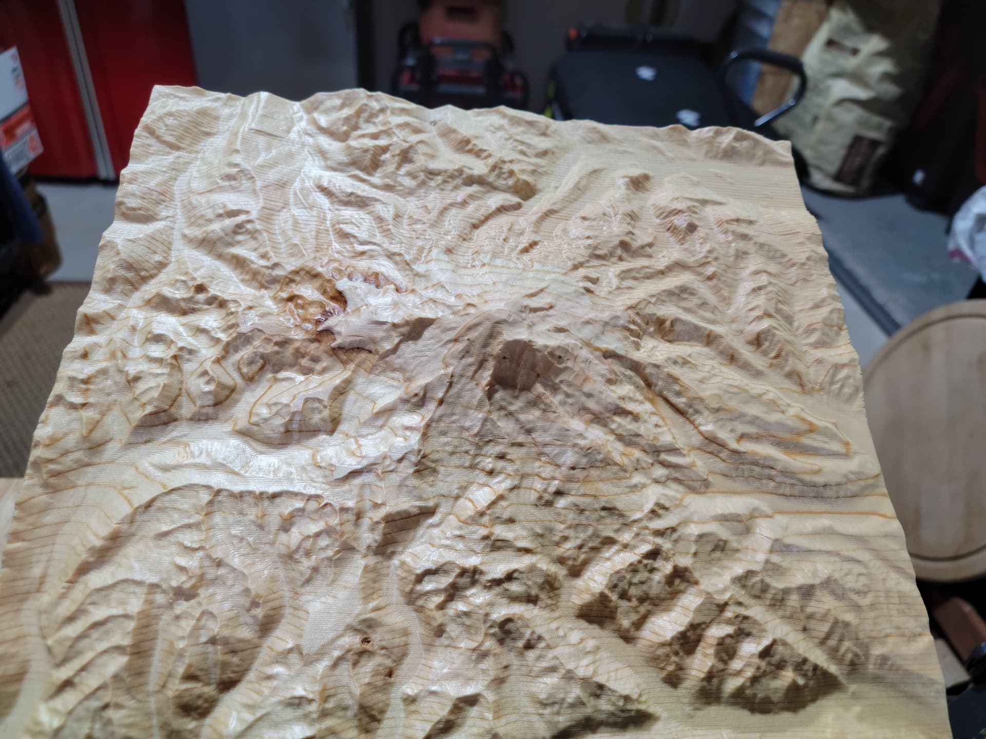
I actually just finished this piece today. My largest Mt. Rainer range yet 10" x 11" x 1.5". It’s just a test piece. Interesting enough, the wood grain in the pine, once oiled, really made the rings look like topo lines. Can’t wait to get my laser and experiment more!
Now if you can adjust the thickness of your pine layers to match the Z distance of the map’s topographical setting the lines really would be accurate!
Actually, those lines can be changed by using a different type of glue. I usually see waterproof glue lines more. How about experimenting with adding color to the glue (since it isn’t really structural) to change the visibility of the “topo” lines?
martindg, forgive me for what might be a dumb question, but, was that cut on a cnc and then the laser was used to put in the elevation and roads? This is all kinda mind blowing to me.
Right!?! That would make it easier @CrookedWoodTex. LOL. Damn mother nature.
This material is just cheap HD pine boards that I used as shelving at some point in the garage. They are 11.5 x 6 ft long x .75" thick. I just cut a couple of them down and glued them together to get 1.5" to accommodate the peak. Pretty simple. But I like how it came out.
Your idea of laser etching in shading would be awesome. They make shader maps, but I haven’t seen any online sources that allow me to download them as a SVG or any other file.
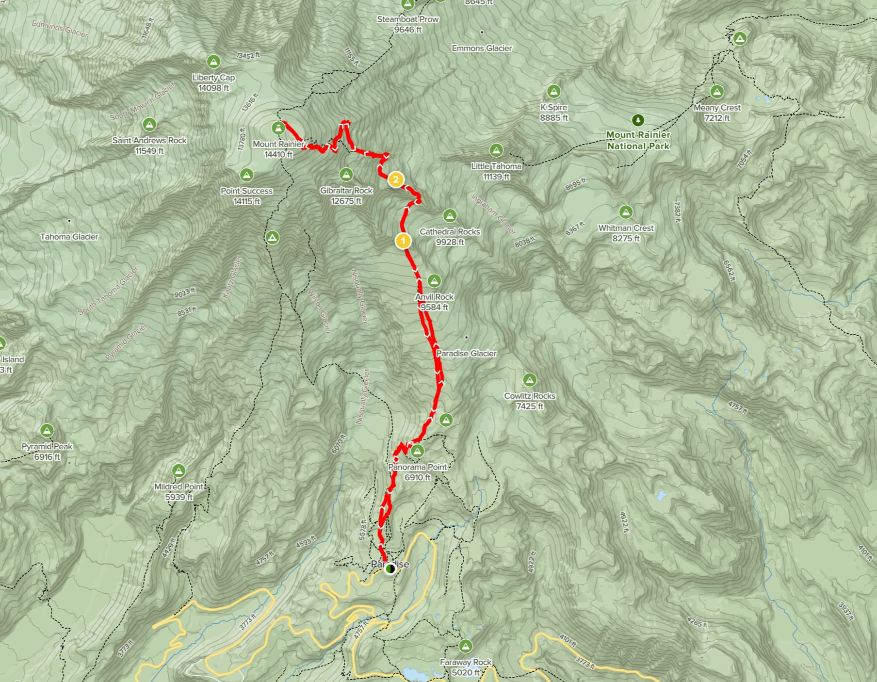
The work that @martindg did is similar to how I would like my finished product to look. Even if it isn’t topo lines on the map, it would be nice to get the standard climb to the summit on there. Depending on the size of the model, it could create the challenge to the beam to traverse 3.5 to 4" in Z.
I response a couple of the questions about the map project. @MikeH you are correct in that the 3D maps was was first cut with the CNC and then I used the laser to etch on top of the 3D model.
The process is fairly straightforward although a bit time intensive also. To begin with I use Aspire. I know its pretty pricey but it has the capabilities that I wanted to use for the projects I wanted to so I bit the bullet and went for it a couple years ago.
Similar to what @Lutraphobia described, I use TouchTerrain (https://touchterrain.geol.iastate.edu/) to grab the STL model of the area I’m mapping. (Very similar to map2stl but I prefer it as it gives me a little bit more control over the actual are that will be modeled.)
I then grab a screen capture of the 2D map on the TouchTerrain site to get a bitmap of the basic landmarks (e.g., roads, buildings, waterways, etc.). I would like to be able to get a vector based representation of these landmarks but I haven’t been able to find a suitable site for that type of file. I will also sometimes grab bitmap maps from the ArcGIS site if I want more landmark details. Since these are bitmaps I will use the Aspire bitmap trace function to convert to vectors. This can be a pretty tedious part of the process as the bitmap first need to be rescaled to match the STL model (which can involve a lot of trial and error). Once scaled to size I next run the bitmap trace to get the best set of vectors I can. This involves manipulation of the bitmap (changing contrast and game levels, etc) to get he best trace and then quite a bit of node editing to get the vectors cleaned up and useable.
At this point I have the 3D model that is scaled to the stock that I’m going to use and the overlaying vector for the landmarks that I’m going to etch into the final project. As to the stock I just use 3/4" HD plywood laminated into a 1.5" thick blank. I like the plywood as the plus give a pseudo-topographic effect and the different textures of the plus provides some interest to the project.
Carving the 3D model is pretty straightforward using a 1/4" ball nose as a clearing bit and either a 1/8" and 1/16" tapered bullnose for the final pass. (I also use Aspire’s 3D modeling tools to create a uniform 1/8" deep pocket for the the lake that is created as part of the 3D carving process and then eventually resin filled.)
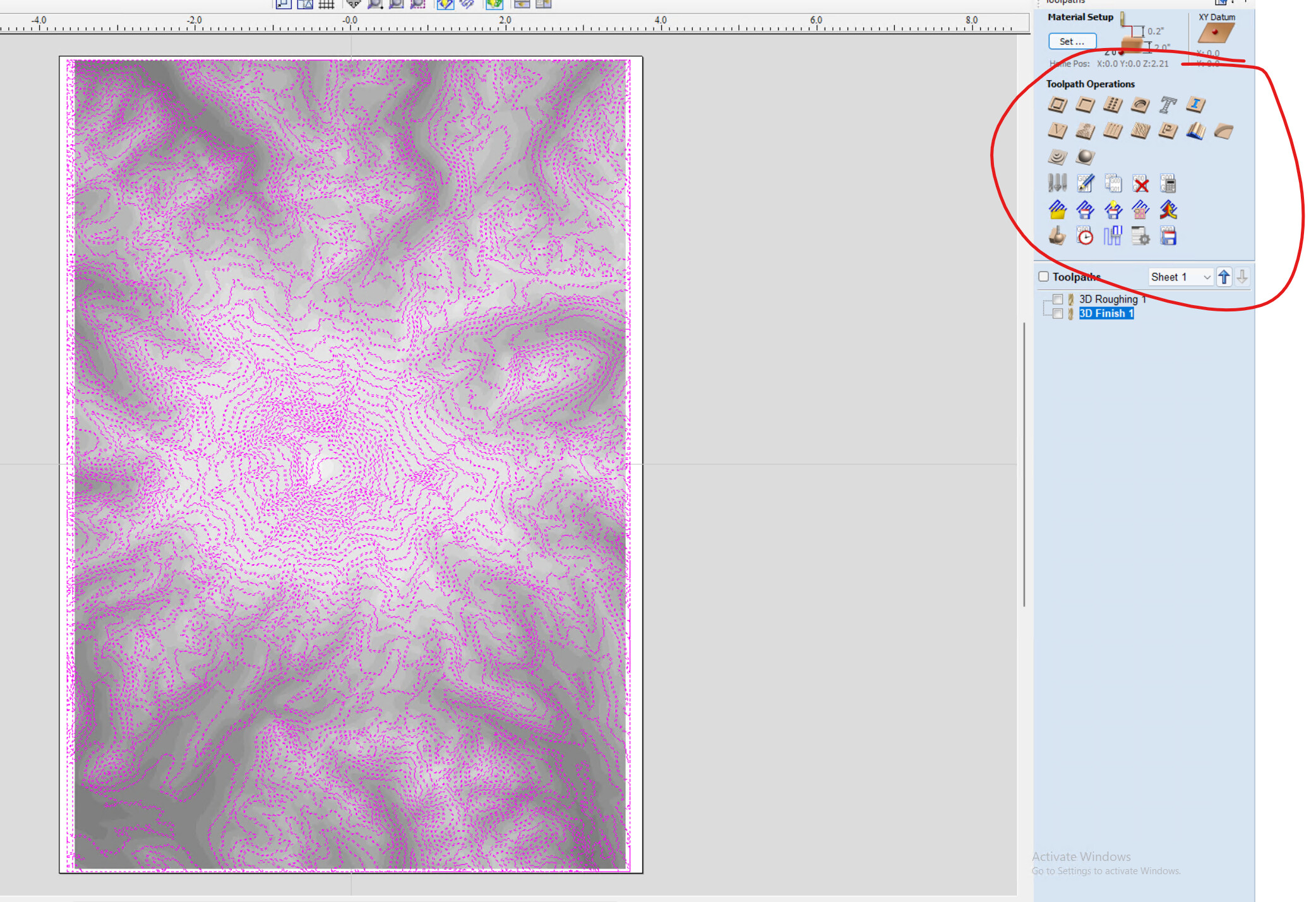
As for the laser etching, I purchased a 3.6 watt diode laser off of Amazon for $90. I 3D printed a mount for it that attaches via magnets to my Z axis. The laser has a focusable lens so the distance between the laser aperture and the work surface can be changed from about 25 - 60ish mm. I created two post processors for generating laser tool paths; one that incorporates Z movements into the laser tool path and one that omits all Z movements. When I laser etch flat parts of the project like the compass rose and the legend I use the post-processor with no Z movements. For etching the landmarks on the map, I generate the tool path using the “Project onto 3D model"option and then use the post processor that includes Z movements. To actually do the laser etching, I determine that maximum depth of the model (which is usually around 1.25” or 40mm and I focus the laser to a little more than that depth so the tool path can follow the 3D contours without bottoming out.
I suppose that may not make much sense but let me know if there are any specific questions about this process.
Wow! Thank you so much @martindg. I appreciate the detail you provided here. Yes, very similar to what I am doing. I love that you created the “Z” laser movement. Would you mind sharing that post processor that incorporates Z movement and explain how the laser is controlled by the software (on/off) while moving between vectors?
As to the post processors…I have a OneFinity Woodworker but instead of the OneFInity controller I use the OpenBuilds BlackBox. I use gSender for sending g-code to my machine (which is the best GRBL-based gcode sender IMHO and how I got the this forum). As mentioned in my previous post I use Aspire as my CAD/CAM software. Anyway, as I am using the OpenBuilds BlackBox controller and gSender I do all of the g-code stuff under the GRBL umbrella. In Aspire (and all Vectric products - I think - such as VCarve) you create custom post processors using a template file that defines how you want the g-code to be formatted and generated. For the most part the default post processor templates will work without modification. I modified them a little bit as I wanted to put some project information in the header bit the actual g-code movement portion of the template is basically unaltered for both my router/spindle and laser post processors. The one big exception to this is that I created a second post processor for my laser and I removed all references to Z axis movements in that file. I titled this “GRBL_No_Z” and if I use this with a toolpaths the tool path will be generated with no Z movements (such as I mentioned for etching the compass rose and legend). If I use the unaltered post processor for a tool path and set the ““Project onto 3D model” option the g-code will move the laser in the Z Axis also. Below are two quick examples of the post processor template files showing one with Z movements and comparable portion of the “No_Z” post-processor showing that I simply removed all Z references in the template so no Z movement will be inserted into the g-code.
Commands output for feed rate moves
±--------------------------------------------------
begin FEED_MOVE
“G1[X][Y][P]”
In terms of controlling the laser so it fires correctly from vector to vector, fortunately GRBL takes care of this for me. GRBL has a laser mode setting; setting $32 = 1 puts GRBL into the laser mode. ( In gSender selecting the Laser Mode setting in the Spindle/Laser control panel will put GRBL into the Laser mode. When in the Laser Mode (i.e., $32 = 1) the controller will manage sending a signal to the laser to get it to fire at the correct power output and will only fire the laser when the X and or Y axis are in motion to prevent scorching at vector transition points. (Thats a pretty general overview of laser Mode. The GRBL home page has a much better explanation.)
@martindg Thanks for writing all that up, Doug. I do something very similar to you, but I’m not as talented as you are, so I just downloaded and installed the Jtech PP for lasers, which, like yours, has no Z movements. For a simple etch, I use it. For burning on 3D, I just use the gbrl in pp that is loaded in VCarve. Like you, I check the project onto 3D model box and vc does the rest.
I’ve created a fake end mill in vc that I use to create the tool paths for my laser. I set the diameter to the spot size of the laser. I change the speed depending on the material. It seems to work quite well.
I’ve been told by others that have done this quite a bit, that in Vectric products (at least) one should trace the bitmap when it has full resolution and resize the resulting (and cleaned up) vectors. Kind of reverse of what you are doing. YMMV
Yeah, that wasn’t clear. I will always try to trace at the highest resolution I can get and then resize. Even at that, the bitmap trace process is wildly inconsistent. I will also play around with altering the contrast, brightness, gamma, etc of the bitmap to try to get the best trace possible. Even with a great trace the process still involves some degree of node manipulation and editing. Thankfully, at least in my opinion, the outcome is worth the time its takes to get there.
Hi @martindg! Thank you so much for the details on the PP.
Also, @gwilki - I followed the directions to the Jtech Laser PP as you mentioned and created a tool in my VCarve trial. However, I don’t see any tool paths on how to use them without installing the Laser add on that brings in two new tool paths for laser and “snapping to 3D model”.
Is there a way to add the laser tool paths like the laser add on from Vectric? Or is there just the tool that is created? If it’s just the tool that is created, where are those other options? Let me know if I am not being specific enough? When I get back home, I can take some screen shots, etc.
Thanks again to everyone chipping in here and educating us!
@Lutraphobia Without the Vectric laser module, there are no specific toolpaths. You can use any of the toolpaths that you would use for a cutting tool. For example, I did an Aztec calendar where I used a v-bit to do all the carving. Then, I simply created another v-carve toolpath, but chose the laser as my tool, rather than a v-bit. I used the Jtech post so that there were no Z moves, and burned inside all the grooves that the v-bit cut. You can use the photo-vcarve tool path and choose your laser as the tool. The Vectric laser module takes all these options and sets them out in a way that makes them easy to choose from and use. The module has value, just not enough for me to justify the cost.
If I am not doing a project that is both cut and burn, I tend to do it all in Lightburn. It is much more powerful and feature rich than the Vectric module and it is less expensive. As with all software, we all have our wish list and our price point. Yours may well not be the same as mine.
@JayDent Thanks for adding this, Jay. I’ve not started playing with this yet. I think that I will, though, just as a challenge.
It seems to me that the first challenge will be to actually get the topo lines or roads or whatever else we want on the 3D carving properly located on the model. After that, Vectric will take care of following the contours of the model with the “line” tool path - something that LB apparently cannot do. I do 3D models all the time with carvings on them and the VCarve functionality works well.
Once the lines are established, I believe that it should be possible to simply set up VCarve using a dummy v-bit to carve them, then use the laser instead. Time and experimentation will tell, I guess.
Sorry if I’ve missed something previously posted, but you can use the project toolpath onto 3D model check box. Vectric Vcarve will follow the contours using a laser toolpath. Now, I’m assuming that you have the Laser Module. Seems like I remember that you don’t.
PS. This is not well thought out, because I’m going camping in just a few minutes!
@CrookedWoodTex That is what I am saying, too, Tex. I don’t have the laser module, but I don’t need it to do this. I simply created a fake tool in the database and select it when I use the laser.
If you were camping in my neck of the woods, one of the implements you would need to take would be a snow shovel. Have fun.
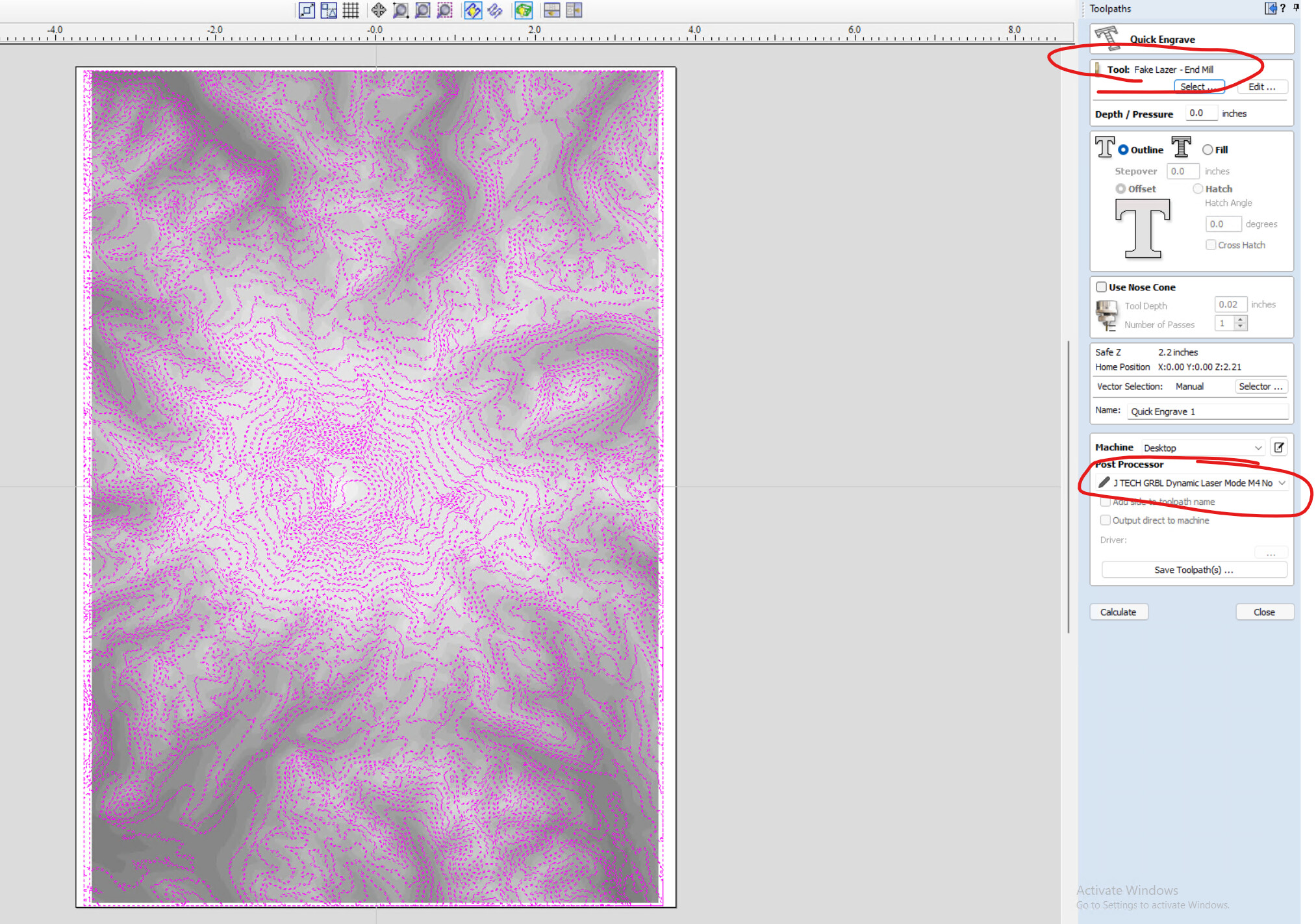
I don’t know how you all are setting up your fake tool in VCarve? Following the JTech instructions here, they state to create a end mill tool. However, when I go to use the “Quick Engrave” tool path, it doesn’t have “Project Toolpath onto 3D Model” is not there.
Frustrating. How do you all have your tool set up to use the v-carve solution? Did you create a fake laser using an engraving or v-bit setting? If so, can you share that?
Might look at the kiri:moto solution that was described here from the LB Forum by @JayDent
@Lutraphobia I’m likely giving incomplete info. I apologize.
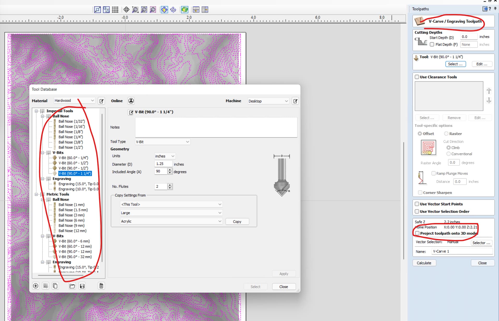
When I say “fake bit”, I mean only that, in vcarve, I am setting up an end mill or a v bit, but actually using the laser for the tool path. If you want to use the laser for a tool path that you choose the v carve operation, you need to have set up the “fake” bit as a V bit. Vectric only shows choices that it allows for any given operation. If you choose the profile operation, you have a full range of tool choices. In other words, you can have set up a “fake” end mill, using the parameters of your laser or a v-bit using the parameters of your laser. Both the v carve operation and the profile operation give you the option to project the tool path onto a 3D model.
If you want to use the quick engrave operation, it will work very well on 2D carvings such as the one that Jtech did for the calendar. Clearly, it will not do what you want on 3D models.
The Jtech Aztec calendar example did not have any 3D modelling functions so they did not need to decide which operation they were choosing with respect to the ability to project the tool path onto a 3D model.
I read the information on using Kiri Moto and it is certainly an option you can explore. I’ve never used Kiri Moto, so I can’t offer any advice on that. I suggest, however, that VCarve is much more feature loaded and can certainly do what you want to do. I’ve done many projects where I have created a 3D model, then run a tool path that carves into that model. Checking that “project toolpath onto 3D model” box yields perfect results with no calculations necessary.
You may want to look at videos by Vectric and by Mark Lindsay on his Youtube channel for tutorials on how to use this feature in VCarve.
Ah. I see @gwilki. I jumped online after a meeting for work and found a YT video about using the profile path. So, that is exactly what you’re telling me as well. So, it all lines up! I suppose I can also use the JTECH PP as you mentioned and edit it for all Z operation as @martindg points out.
All very super helpful!
I believe that the firmware for the LM30x30 is 1.1, correct?
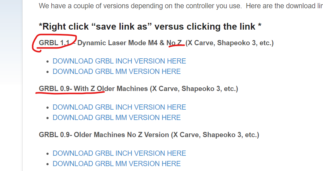
Do you know if there is a reason JTech didn’t make a 1.1 Dynamic Laser Mode M4 with Z? Only .9 is listed with Z. Are there any I gotchas for editing the PP?