@Lutraphobia Just to be clear, I’m not telling you that you must use the profile operation. I am saying it is one option for what you want to do. Another option is a v carve operation.
The Long Mill does use grbl 1.1h
I have no idea why Jtech has a newer version for no Z. If it’s important to you, I would imagine you could ask them
I have never edited a post processor, so I have no advice to offer. One of the reasons that I have not done it is that there are a lot of things that can go wrong and I’ve never needed a custom post processor.
With respect, since you don’t need to edit one to do what you want to do, I would strongly advise that you not do it. It’s your call, though.
Great advice - I’ll ask Jtech if they can make a 1.1h compatible PP with a Z.
Understood that using pocketing tool is just one option. I’ll just get v-carve pro and the laser add on at some point. Making it simple and consolidating my tool paths and workflows may be worth the money.
I wonder if they have veterans’ discounts or sales at certain times of the year?
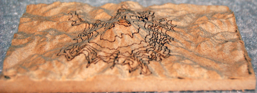
Well, here is my test piece. It’s small - only 4 x 6. It’s cut in 1.25" MDF.
I took the stl of mount rainer that @Lutraphobia posted on this thread and cropped and resized it. Then I took the contour graphic and played a bit with it. It likely is not spot on, but as this is a throw-away piece, I wasn’t concerned.
I created 3 tool paths in VCarvePro. A roughing pass and a finishing pass for the topo map and a profile pass for the contour lines.
I chose a 1/4" ball nose for the roughing pass, a 1/8" ball nose for the finishing pass and a .005 diameter end mill for the contours. .005 is the diameter of my laser spot. I set the spindle speed to 500, which is 50% laser power. I set the feed rate to 3500 mm/min.
The roughing and finishing passes were done using the named bits. The contours were done using the laser.
I set Z0 on the surface of the material for the roughing and finishing passes, using grbl inch as the post processor.
Before setting up the laser pass, I set $30=1000 and $32=1. Then, for the laser pass, I tried something different. I set its focus on the surface of the material and also used grbl inch as the post processor. That way, the Z axis moved up and down as if I was using an end mill (which, to VCP, I was). Using the feature in Vectric to “project tool path onto 3D model” meant that the laser followed the contour of the topo carved by the router.
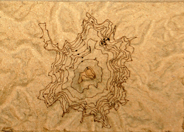
The pic is not very good, but the lines are a consistent width and level of darkness from the highest point in the model to the lowest. The max height of the model is just under 1.25"; the lowest is just under .25". I am using a G8 lens and the focal length is less than the 1" difference between the highest and lowest point in the model. So, I believe that if the Z axis was not following the contour of the model, the results would not be as precise as they are.
Awesome test, details on how you accomplished it, and outcome.
Thank you very much @gwilki for helping here. Can’t wait to get my laser from Sienci to get started on this. I think you just made it super simple with the details described below.
Looks like I need to back off on the power a bit and increase the travel speed I am thinking. The lines are a bit bolder than what I intended it to look like.
Anyway, QQ to @gwilki or anyone else. When I screwed in the laser lens, it was quite a loose fit.
Yes, I put the correct spring in (7mm for G2 if I recall correctly). With the laser on and trying to focus it turning the ring I find that it’s super touchy. I thought it would be more of a perfect fit. When you touch the focus dial the beam bounces around a lot.
I wanted to do this for Sunshine Canyon in Colorado and show the various routes to Gold Hill for Xmas presents for family. However, I just installed the SLB which using grblHal and not grbl. Will this be an issue?? I’ve not used a post processor before so that part is a bit muddy still until I try.
A bit late but what the heck. I have the same issue with the laser-lenses. It’s why I cannot work with a standard macro offset to the mill and have to dial in the laser using a dimpel set with a v-bit. I can’t use the focussing tools either and have to eyeball that aswell.
I like to think it’s more accurate, but wonky them lenses are and it’s a miracle they dont shift during jobs (yet)
I’m a bit late on this but I know that with Vectric and the laser module you can use the ‘Project onto 3D Model’ so that the laser stays in focus.
I’m not sure about the J Tech post processor though, maybe @gwilki knows. I’m not sure if all of their PP’s remove the Z moves. This maybe mute if your laser has a focus range. Mine needs to be a constant distance to not get fuzzy lines.
I haven’t done a relief map yet but it’s on my bucket list. My laser rides 20mm above the surface and isn’t too wide so I think I could use Project onto 3D model as long as the mountains weren’t too high and steep.
Daaaim, need to look into that function.
I do project onto 3d pieces cause the sienci module has a few lenses that have a rather large focal range but it is still limited. Project onto a model with z movement would make things so much easier.
Thanks for the headsup, this would revolutionize the way to do projections! Wait, this means I’m going to have to betrail lightburn, isnt it… Ohno tears!
So psyched to try this out! Ill report back on it, if I remember where this post is.
@_Michael Sorry for the late reply, Michael. I missed your referral somehow. As far as I know, the Jtech post for laser stops Z movement. In fact, a quick comparison between it and the standard grbl mm seems to show that is the only difference.
I have run my laser in VCarve using the grbl mm post and setting “project on 3D model” in a profile toolpath. I fake the tool. I have two fakes in my tool database. One is an endmill with a .005 diameter, which is the diameter of the laser spot. The other is a fake vbit.
I caution anyone trying this to do test pieces and to have your hand on the panic button the first time. I’ve had no issues, but my process comes with no guarantees.
I think that LB is worth having just for photos if nothing else. It is vastly superior to the Vectric Laser Module when it comes to images, both in image manipulation and the actual burning.
FYI if your not aware you can bookmark a post, the option is under the three dots menu. Then you can view your bookmarks in the drop down when clicking your avatar in the top right. I have found it useful.
Yeah, I looked at a vectric tutorial using a model and an etch. It didn’t show any results, but I saw I didn’t get to use this for free. I am prohibited from investing anymore untill I can generate a somewhat steady cashflow so my enthausiasm ended right there.
It went into a mind-drawer, to be openend at a later time. Untill then I have to mud wrestle my carve-laser combos old school.
I’ll manage.
Bookmarks I make, but have never looked back. I suck at online things.
Is it Vectric that you don’t have? I’m only asking because I don’t think the Laser Module is worth the money considering you can just set up a fake tool like Grant said.
I have a v12 vectric pro version but not the laser module.
I may ask Grant to maybe elaborate on the fake tool thing. Can it turn on off laser, toggle power etc? I Couldn’t comprehend it’s workings so I set it aside to look into when I have a long job running and time to be bored.