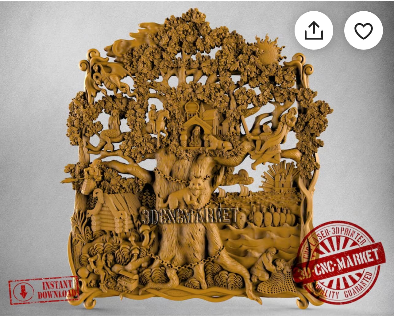
I could use a few tips on setting vectors ant tool paths on my 1st attempt on a carving inside Vectric Vcarve desktop. I’m a beginner and have a few 2D carvings created (somewhat painstakingly), and have purchased a file online to give a try.
After getting it set up the best I can, then after calculating, the parts of the file that should be machined all the way through are the opposite. I’ve tried to layer, set vectors and get frustrated because I don’t know how to set them. Any help is appreciated.
If I could find a sheet on this project that I could send right to Gsender (gbrl), I could study the settings and what not which would help me learn. That would be sweet!
Thanks
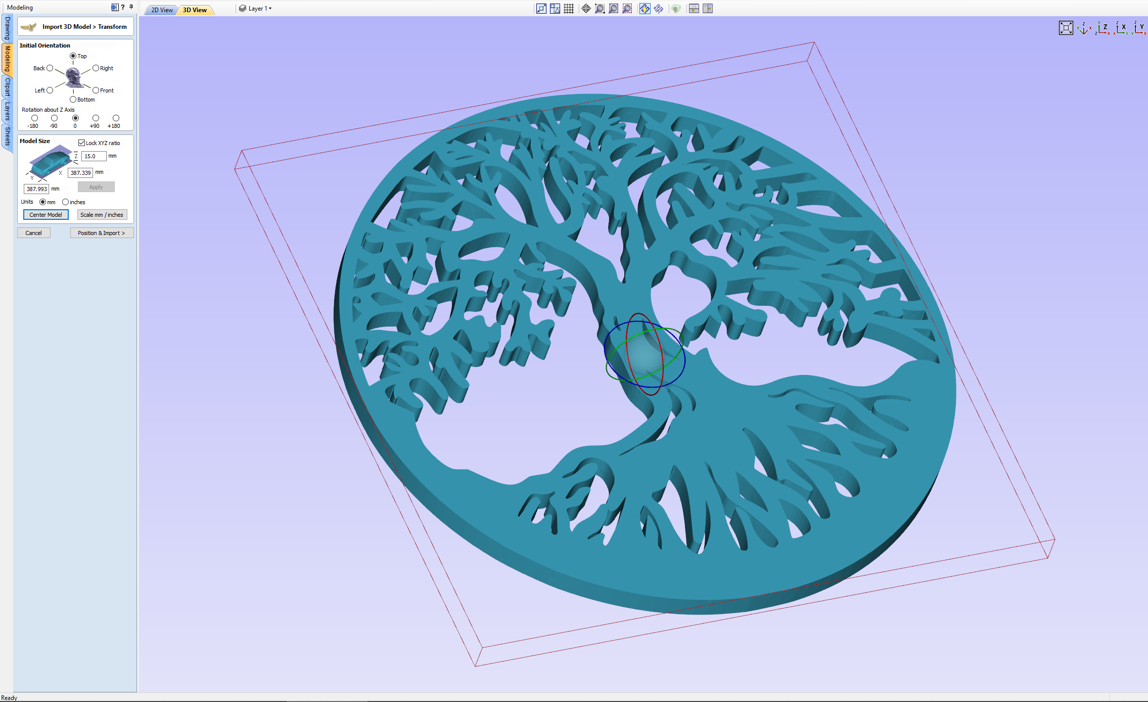
I think the most important steps in 3d happen in the material setup screens. I’ll show you how I do it.
On this screen I make sure the model is centered and orientated the way I want it. I am using a much simpler tree of life model found on Thingiverse.
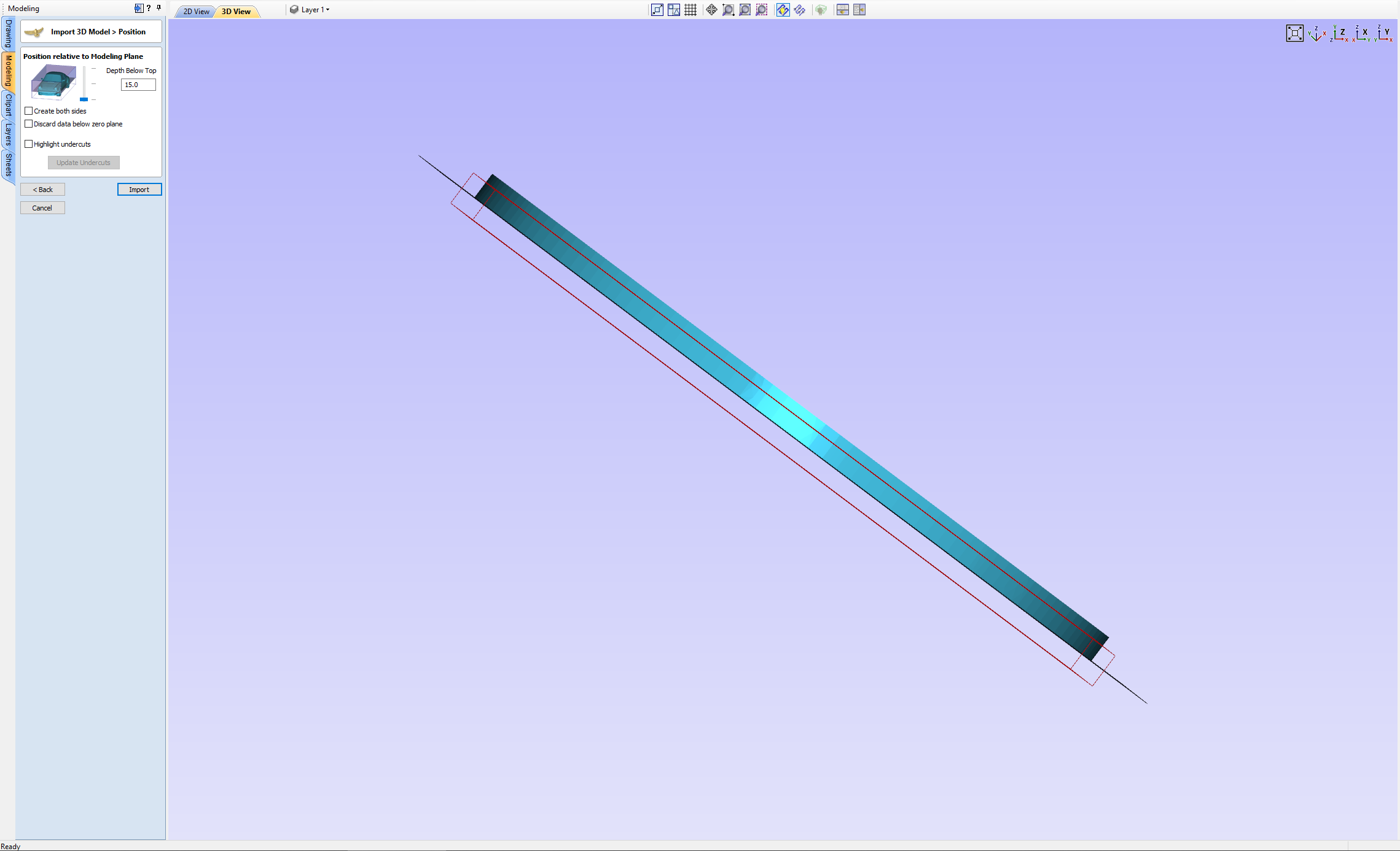
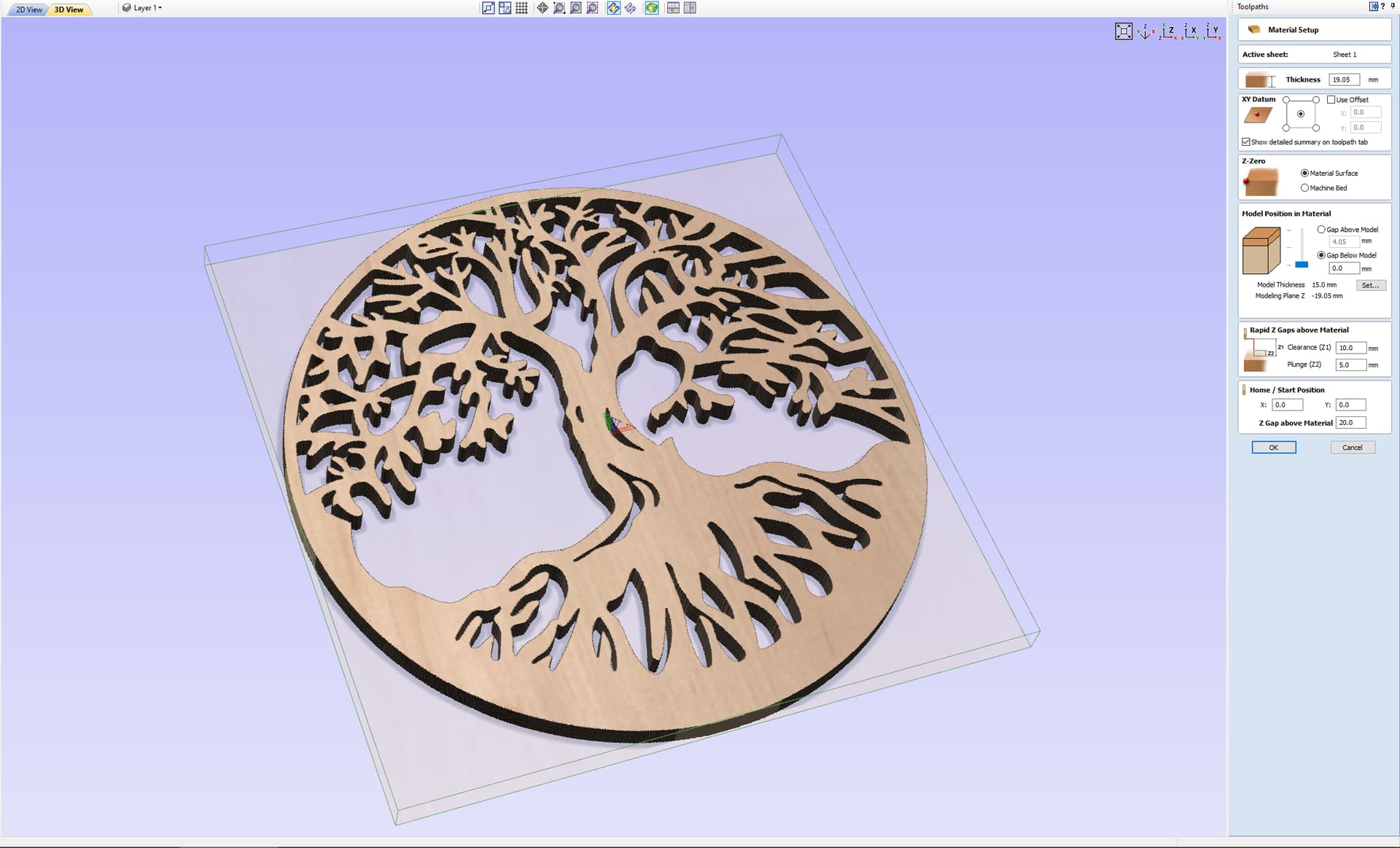
On this screen I have moved the slider down so that the model sits on the Z plane.
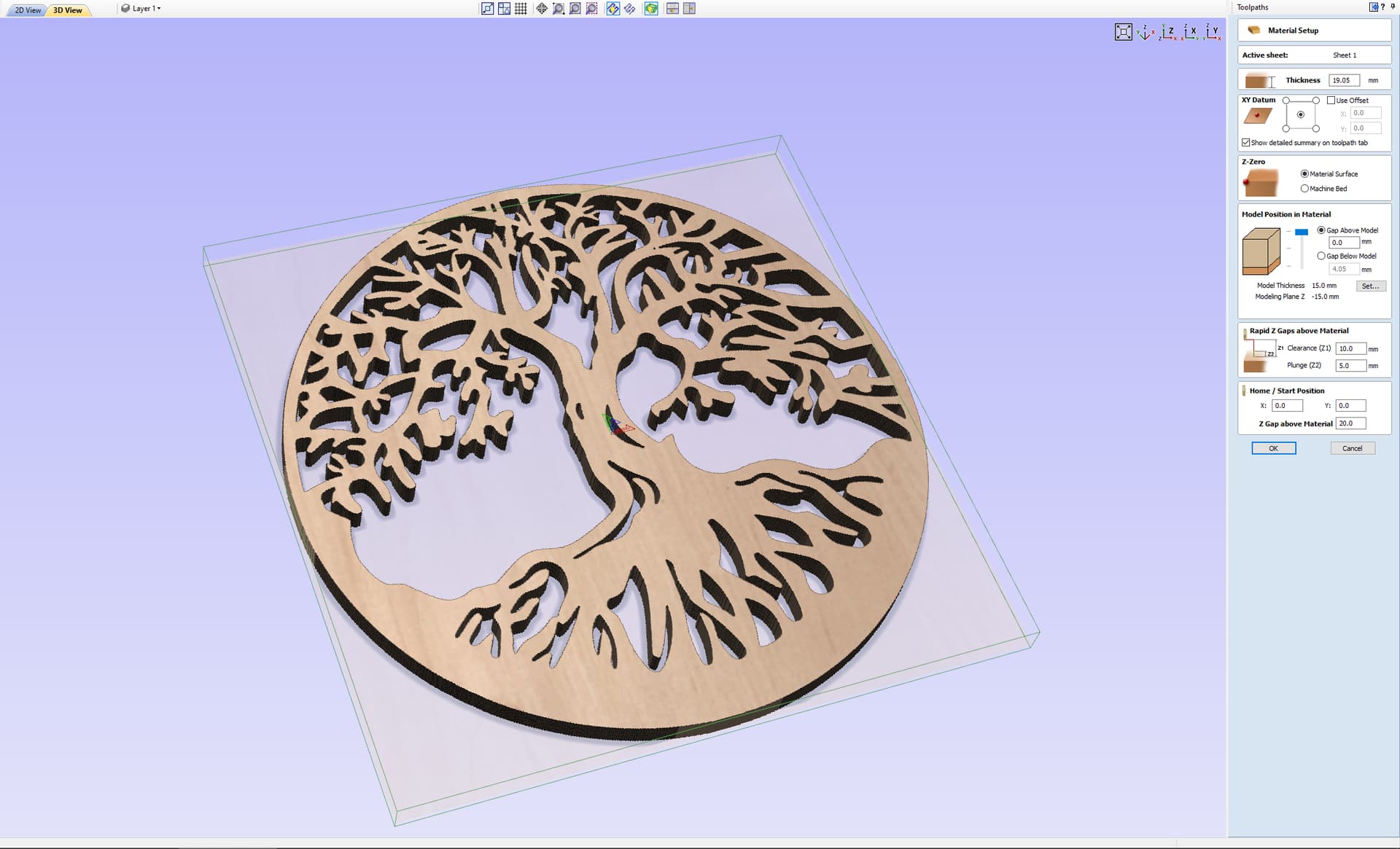
Then when selecting the 3d roughing toolpath you are brought to the material setup that lives in the right sidebar. You can also access this through its own icon if needed. Here you can see that the model is positioned at the top of the material and any extra material will be left on the bottom, not cut all the way through.
Here I’ve changed it so the extra material is on the top with 0 space below model.
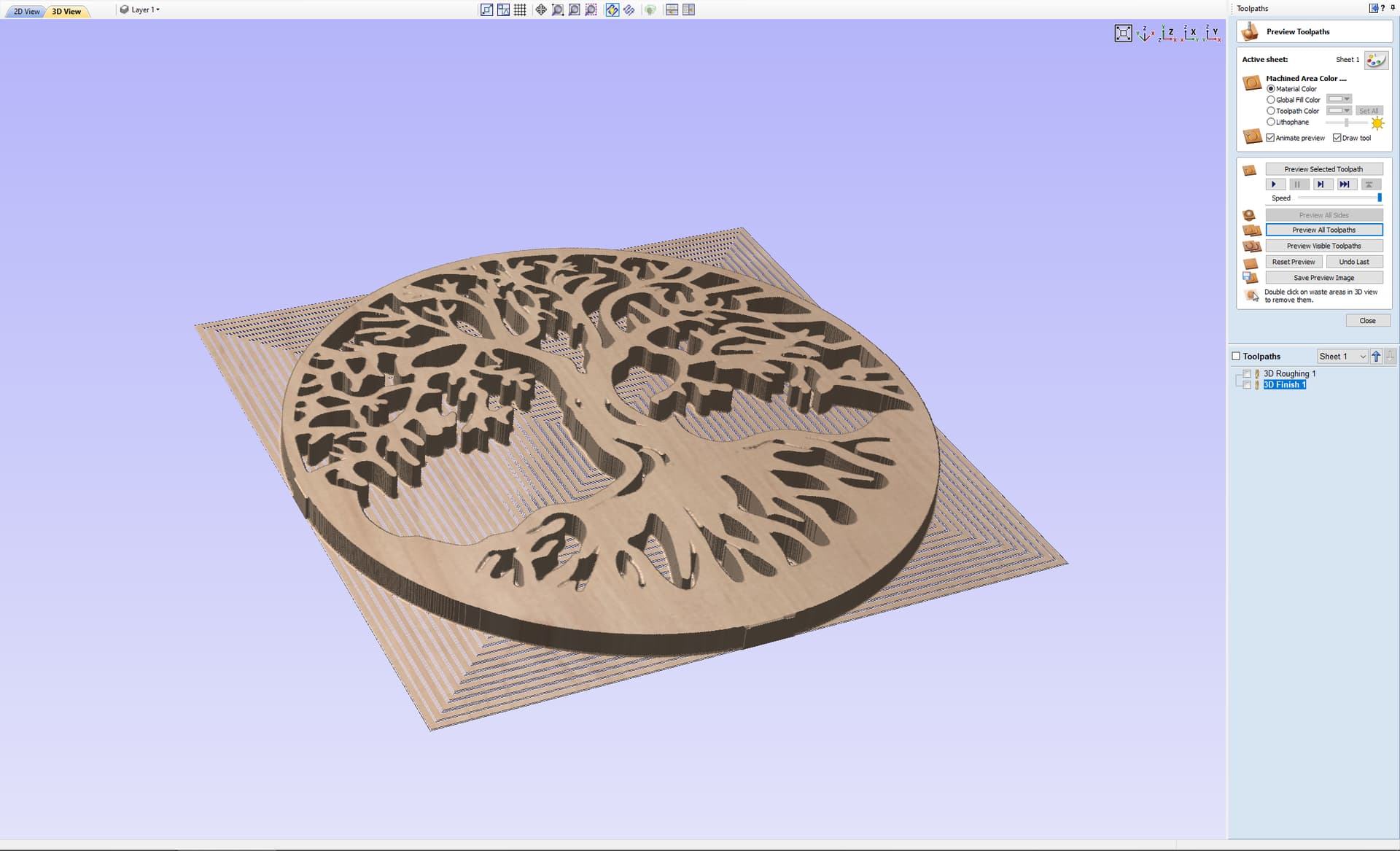
This is my final preview which is cut all the way through even though it looks like vectric is having a hard time rendering it. I skipped the toolpath creation but can go over that if needed.
I hope this helps, please follow up with any further questions if you can’t get a good preview.
Edit: Here are the files for VCarve and the starting stl.
tree_1pieceversion.stl (2.9 MB)
Edit: In the crv file for the 3D toolpaths I used Material Boundary for the Machining Limit Boundary because I was rushing. I don’t usually use that setting because it doesn’t leave room for clamps. A better option IMHO is to use the Create vector boundary under Modelling tools to create a perimeter of the model. Then under Drawing tools you can offset that vector to the outside by at least your bit diameter. Then you can use that vector with Selected Vector(s) for the Machining Limit Boundary in your 3D toolpaths.
1 Like