Adding a Laser - My Journey (Tutorial)

Hi everyone, I’m new here and tried to read up on all the history, so forgive me if I ask a repeat question.

I have been working to add in a Sainsmart laser unit that I had prior to the Longmill (in fact it was largely the inspiration to get a CNC)

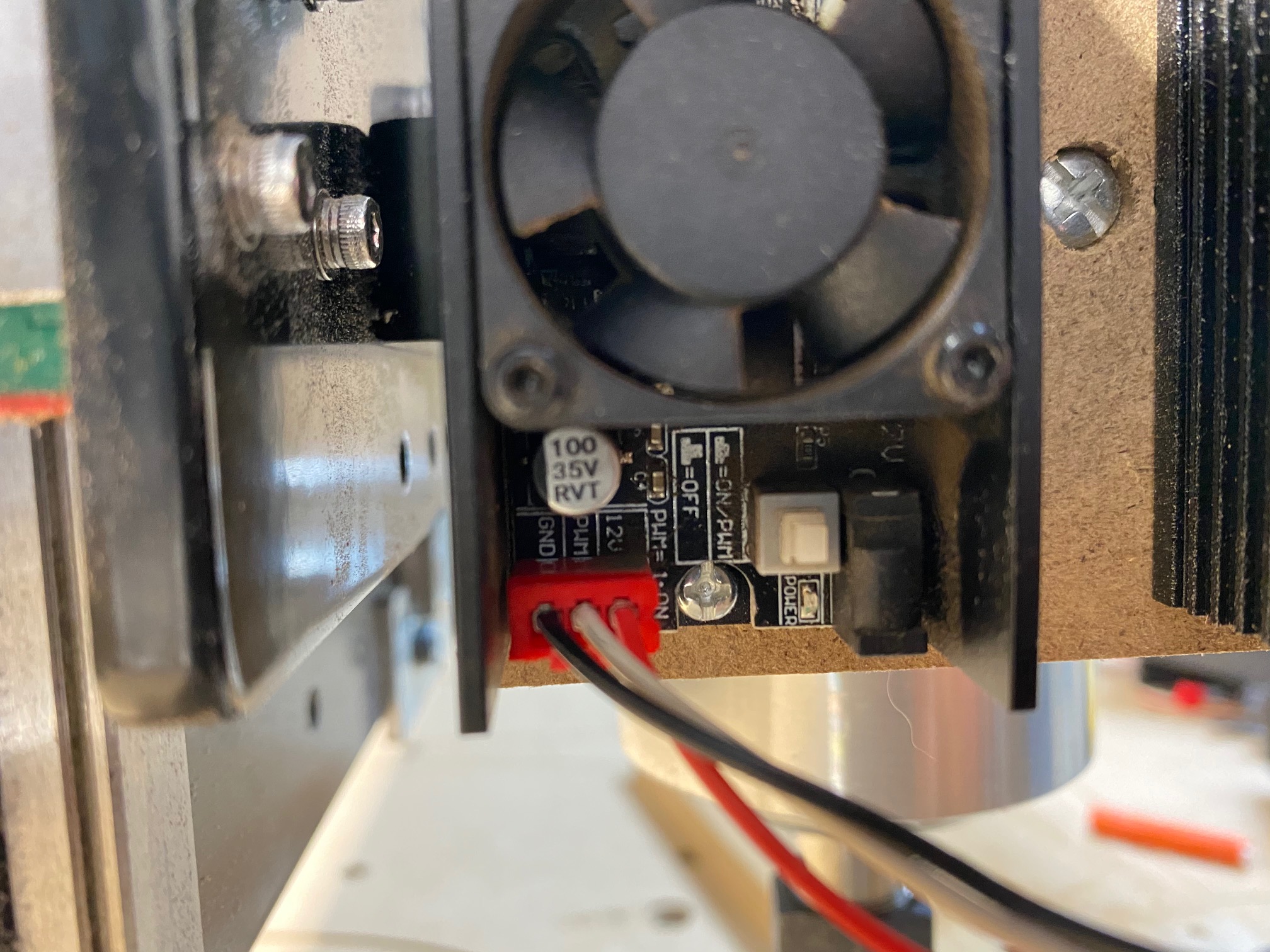
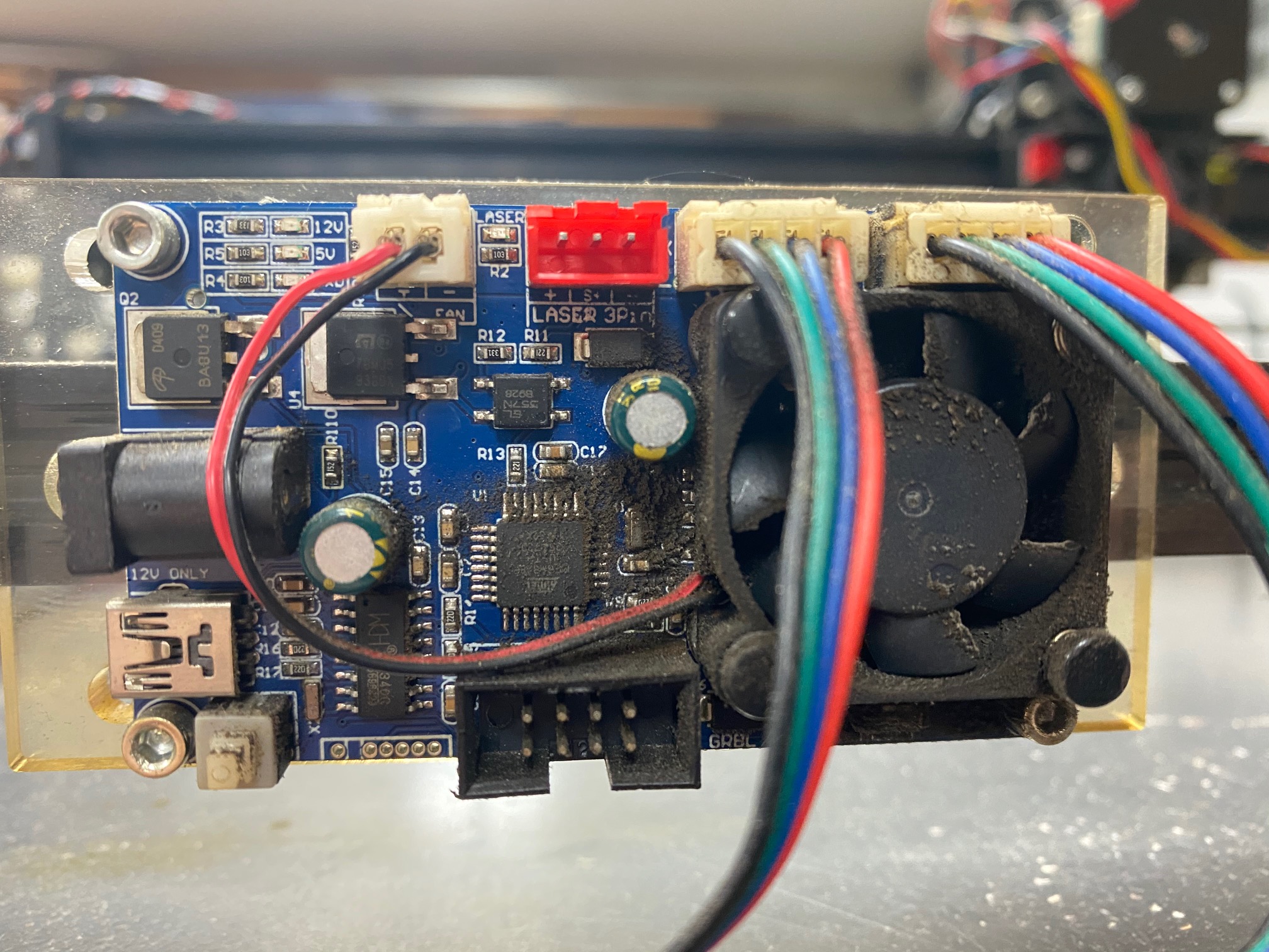
I think this is the driver and laser it came with:

This is a 3 pin connector. I simply tied the grounds together from the 12 VDC power supply and the ground pin on the long board PWM . I then took the SpinPWM pin and connected it to the PWM input on the driver board and connected the 12 VDC to the third pin for power.

I then enabled laser mode and reset the max spindle speed to 100 in the GRBL code

The laser powers up just fine, but the PWM signal is not working right, the laser is always on. Here is a few things I tried/reviewed:

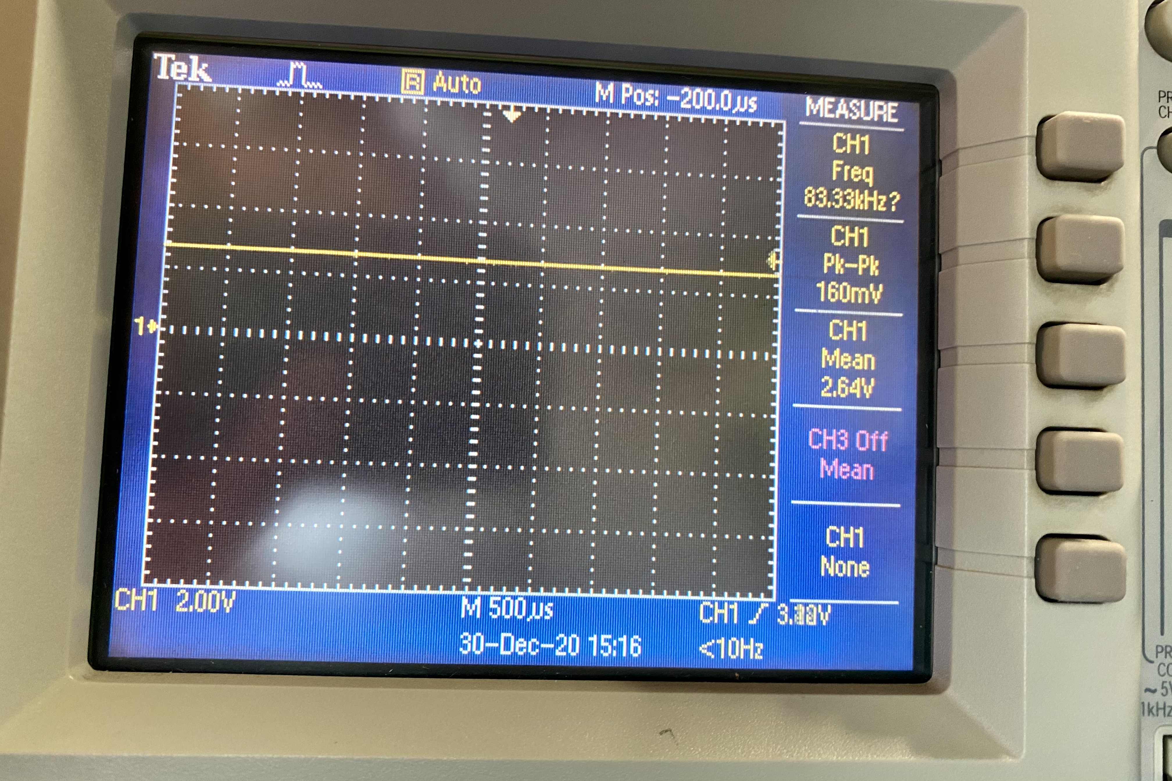
The SpinPWM signal with no load at all (just connected to a DVM) does not scale like I would expect:

M5 or S0 - .188
S20 - 2.83
S40 - 3.40
S60 - 3.88
S80 - 4.24
S100 - 4.46

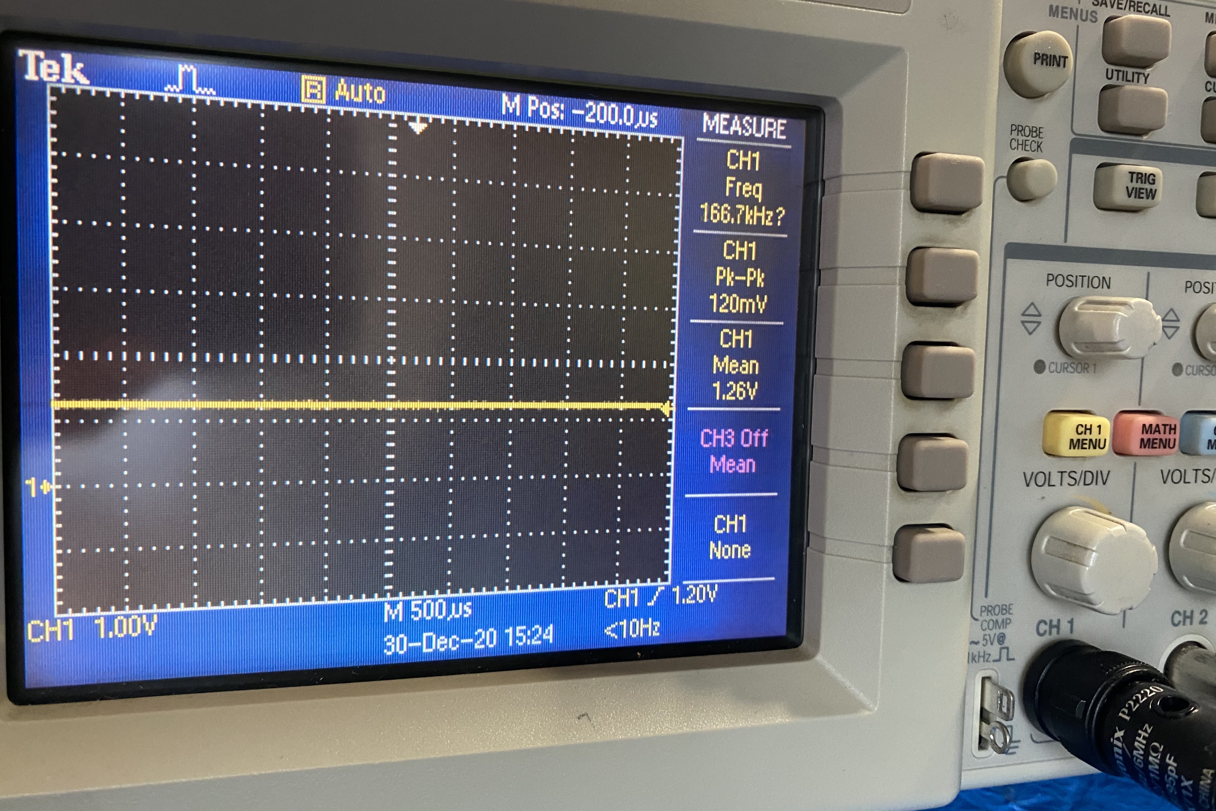
Each of these commands I would expect to result in 1, 2, 3, 4 or 5 VDC, but they didn’t line up that way. When checking the no load output from the Sainsmart GRBL board on the PWM, I get:

s0 - 0
s20 - .96
s40 - 1.87
s60 - 2.78
s80 - 3.69
s100 - 4.57

Another thing I tried is to simply hook up power to the laser and leave the PWM input floating, the laser came on, even with no signal on the PWM. If I tied the signal to ground, it turns off, so the driver seems to need to be pulled down to ground on the PWM input.

One last test I did was to wire in the unit with taps, so I could measure how once it was connected to the Longboard it responded. In that case the S0 command really went to 0 VDC on the PWM while the power switch on the driver board was off. Once the power was turned on, the voltage jumped to 4.5 VDC, without changing anything other than powering on the laser module.

I’m totally scratching my head on this one. The module is good, it works fine with the Sainsmart GRBL board, but somehow it does not play well with other controllers.

Has anyone here used a 3 pin laser successfully on the Longmill?

@JayDent, I posted info on the SpeedPWM signal elsewhere in the forum. Maybe this will help you understand the signal a bit better, although your numbers do seem a bit off. It seems like you connected it properly although I don’t know how much 12V current your laser driver and module draw. I don’t think the 12V output of the Longmill control box is very hefty. You might want to check it’s capability versus you Laser’s max draw.

@JayDent Welcome, Jacob.

I’m a bit confused. When you talk about the 12V power supply, is this a stand alone power supply that came with the laser? In the links that you included, I don’t see a power supply.
@paullarson I think that Paul is assuming that you are talking about the 12V output from the Long Mill controller.

Yes, I was @gwilki

@paullarson That wasn’t a shot, Paul. For me, Jacob was unclear in his post where he was getting the 12V from. The 12v port on the Mill controller will not take the draw of the laser.

@gwilki, Grant, I didn’t think you were. I was just agreeing with you and trying to make things clear.

1 Like

@paullarson @gwilki Thanks for the info and I’ll try to clarify better. Was getting a bit punchy after scratching my head on what I thought would be simple (I really should know better by now…)

The Sainsmart system runs a 12 VDC supply into their GRBL board. That board has a three pin connector out to the laser driver. The pins are labeled 12, PWM, GND.

For hooking it up to the Longmill I purchased a new 12 VDC power supply (5 amp) which should be more than enough to run just the laser (the laser and motors are running on a 5 amp supply on the old unit)

I tied the grounds/common lines together. So the - on the external 12 VDC supply is tied to the GND pin on the PWM and to the laser driver board GND pin. The PWM runs straight from the Longboard to the PWM input on the driver board. The 12 VDC goes straight to the 12 VDC input on the driver board.

I did some more experiments and found that with the power switch on the driver board off, when I connect the driver board to the system it did pull my down the ‘off’ value to 0 VDC from the .188 or so it was floating at before. That was a positive. The problem is when I turned on the laser board (there is a power switch on the driver board), the voltage jumped to 4+ volts (which explains why the laser came on at a high intensity). It seems that the driver board sources some current/voltage and the Longboard can’t pull it down.

I disconnected everything again and started to measure resistance. On the Longboard I measured 1k between the PWM and GND pins and on the Sainsmart board measured 200 ohms. I saw in the other chain someone mentioning that they had to put a pull down resistor across the pins to get another type of laser to work. I’m wondering if that is the case here. I don’t know how much current the PWM driver can source to overcome the resister, but I’m thinking that is the next step to attempt.

Thanks
Jay

Had to post images separately, this is the GRBL board from Sainsmart. It is NOT used in the new configuration, just for reference to my above post

200 ohms on the input seems a bit low, but the laser still works with the original boar - right? Does the switch on the laser board have to be turned on? I’m wondering if it is a switch intended to turn on the laser regardless of the PWM input? I have a switch like that on my laser driver. If that’s the case it may be implemented such that it overrides the PWM from the Longboard. Just a thought.

@paullarson - The switch needs to be on to run at all. And it does still work on the original board.

@JayDent. Just wondering if you got your laser working with the longmill. I bought the same laser and I’m having issues with it not turning on.

@r_heisler, yep I got it working. Put a pull down resistor on the PWM line (1k I think, I can look it up).

My issue was it would not turn off at all, as soon as I powered it up the laser was on.

What is your exact issue?

I have exactly the same issue. Can you check what kind of resistor did you use.
After a lot of reading and trying … I call my brother-in-law ))) who’s doing robotics for living. He got his oscillometer and explained me right away.
Signal from LM controller is too powerful for this laser and constantly was showing 2.5V, when it was On or Off. And he can see the different frequency coming from LightBurn but it’s not enough to change laser burn power… this way it’s burning all the time.

I don’t know what I’m saying ))) sorry if it’s confusing… I’m just a USER :ok_hand:

@Funtik, I used a 1k resistor across the PWM to GND pins.

Your symptoms sound similar, but I found it slightly different. The Sainsmart is sourcing too much power for the LM board to pull to ground. Before you try the resistor, simply turn off the Sainsmart board and the output should work normally. If you still see 2.5 V with the power off on the Sainsmart board, something else is going on.

Basically when I had the power off, the PWM pin would read 0 (or close to it when I asked Lightburn to turn off the laser) and 4.5 when I turned it on to 100%. As soon as I turned on the laser module, it would read over 3 volts no matter what.

The resistor took care of the issue.

Well my issue was i could not control the laser with the longmill board. All I had was full power no PWM control. Then the laser decided to fail, it just got weaker and weaker till it wouldnt burn anything, even the beam was really weak. The SainSmart laser burned out. So I sent it back and ordered a different laser. Hopefully it will be here soon.

@JayDent so I took a few pics to show what was happening without resistor and with it.
This one without:

Next one with 4.9k resistor


We install 4.9k and laser works like a Pro. I can control it from LB no problem.

Just for curiosity :+1:

Happy New Year everyone!

Good to hear. I might try the larger resistor later this week. I just ordered a cheap scope to play with, that will give me a good excuse to play with it.

How did you end up wiring it up? Did you mount the 12 volt power supply on the y axis or run the 12 volt the full length of all the drag chain? I think I used a chunk of 14 gauge extension cord to run the length of the drag chain. I plan to check to see what the voltage drop is at 100% power once I get the scope.

I was looking at the user guide for the Sainsmart laser I think you guys are using. It references a small white switch. Have you got it set correctly? See below.

2 Likes

@JayDent
I extend the wire thru the drag chain. I have used 22ga but now, when everything is working I probably will do 18ga or 16ga of good quality wire. Again, my bro-in-law told me he can supply to me what they using at work ))) and he said 18ga would be more then enough. This project for a weekend and then I would test a difference of it.

@paullarson
I don’t have that button on my laser