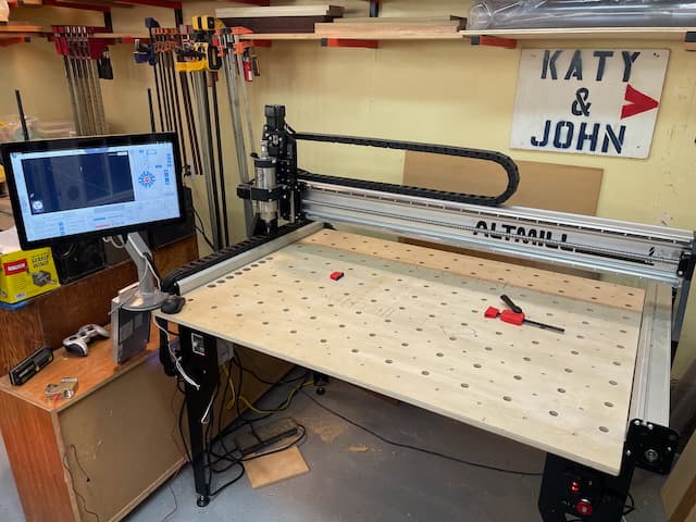
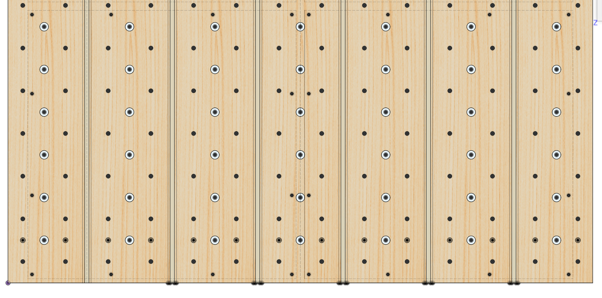
I finished assembling my new 4x2 this week and needed to set up a base board. After looking thru the options, I settled on a variation of Eigen Design’s GOAT concept using a grid of 3/4" dogs and 1/4-20 threaded inserts, but without the t-tracks. I like the idea of using smaller sacrificial boards with a matching hole pattern that can be bolted to the baseboard for cut-through projects, without impacting Z-height for V-carve projects. I also added mounting details for the RapidChange 8-position ATC unit along the left edge.
As a first project on the Altmill, everything turned out great, after a few learning opportunities:
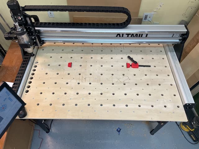
Routing a 51.75x39" board on a 48x24 machine required learning about tiling in VCarve, setting up a temporary sacrificial 4’x6’ bed so I didn’t cut into the aluminum rails, and finding a 6mm driver bit for my cordless to make installing 120 inserts possible. Before final install, I made sure to align the grid along the machine’s Y axis.
Here’s photos of the result, as well as the VCarve 12 CAD files for anyone else who feels motivated to build on this idea.
Hows that for a start! I didn’t know this setup had a name. I too went with inserts. Me ofcourse because it was the cheapest option to get things clamped. I however quickly discovered that just using enough to fit this small testing wasteboard, is fine but how about this next larger project, ey?! And since I started a 50x50mm grid with the first batch of inserts, I ended up needing another 3 boxes to fill my complete bed with the grid.
It turned out to use jigs is working like magic for me, but I had to stumble around a few years before I got where I am now.
So it has a name with videos and all? Who knew!
Anyhooo, your off to a great start, with a diverse clamping system that is looking good (yours is, not mine)
Keep us posted on your projects, and not less important, on your clamping evolution and the jigs you are inventing.
One interesting option I’m following is a simple vacuum hold down by an UK entrepreneur called VacuDog (VACUDOG™ – TRACKTUBES™). This system mounts in a 20mm dog hole and looks like it would make a great jig. His first run sold out in a matter of days, but he’s indicated more are coming… Fingers Crossed!
I happened to see the video for this contraption yesterday. In that video the Vacudog was used to hold down a piece of stock for sanding.
There are a couple of thoughts I had - it’s a fairly small surface area that does the clamping (clamping force is directly related to surface area). Yes, you could install a number of these but that will get expensive quickly. You would also need to delete the sheet of material that sits directly on the mill stringers (I am assuming the standard configuration is bottom sheet and then spoil board on top). Lastly, if you have a 3D printer, one could easily give this a try without buying anything.
“contraption” is a good name - it looks to be a targeted solution for working with smaller pieces in a non-CNC environment; my"engineer" background makes me dubious of the durability and effectiveness of reusable foam ring and the impact on uniform work height - but it is an interesting idea anyways
@JPlocher@Jens If you are looking around for clamping methods, you may want to consider “pods”. I made pods out of mdf and inexpensive rubber gasket strings. I already had a vacuum pump for my lathe vacuum chuck, so that was a plus for me. The pods work very well for projects that do not cut through the material, such as pockets and 3D models. They work quite well for cut throughs where the material overhangs the pods, too.
I don’t use them all that often, but they are really handy for projects where I am milling close to the edges of the material, and screws or clamps would get in the way.
Just an FYI.
Could I ask for a picture of what your pods look like?
Did you mill the heights of all the pods in one setup so they are all identical in height when you use multiple pods for a cnc setup? With the pods having a relatively small (I assume) area, have you had any issues with the work piece moving during a milling run?
@Jens I’ll get some pics later today or tomorrow morning. I did three sizes. To be clear, they are all identical in height because they are all .75"/19mm MDF. There was no milling to make them identical.
I have not had any issues with work pieces moving - so far.
PS. There are any nunber of commercially-available pucks, too. I’m just cheap.
@Jens I apologize, Jens. Until this morning, I forgot all about my commitment to send you a pic of my pods.
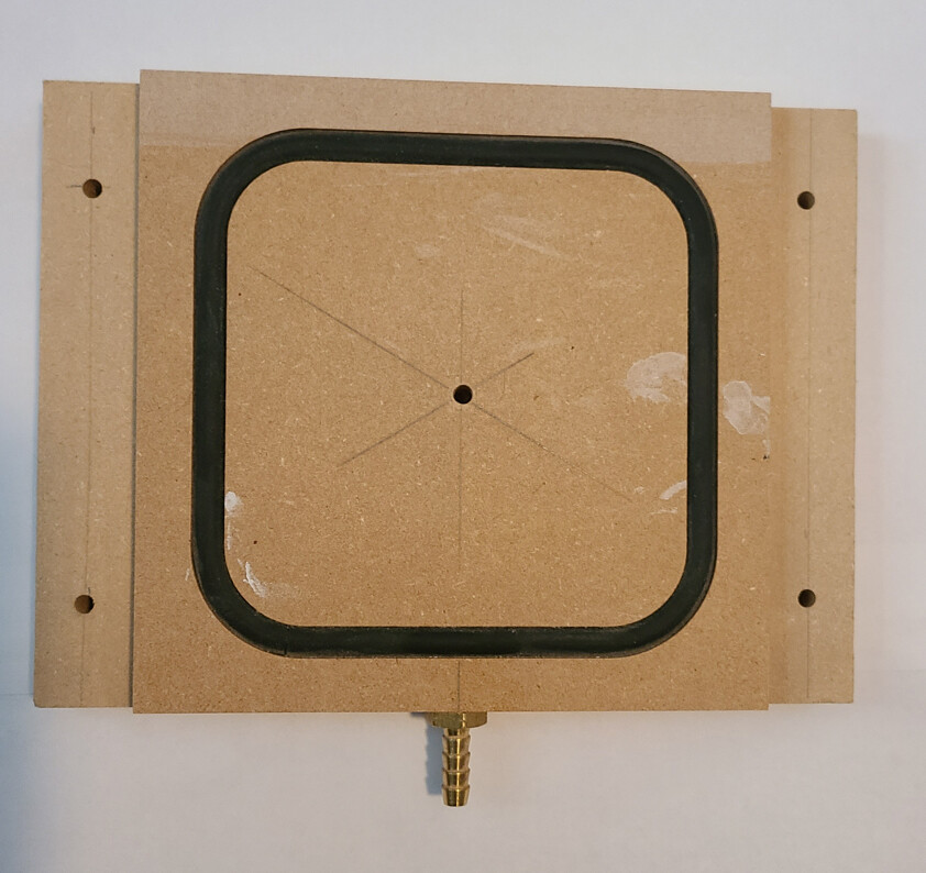
Attached, finally, is a pic of one of my 6” pods. I have 5” and 4” also. As you can see, they are very simple. I have a vacuum pump that I connect with 1/8” tubing to the inlet. These are very basic, but work quite well. I either clamp them down to my spoilboard or screw them down.
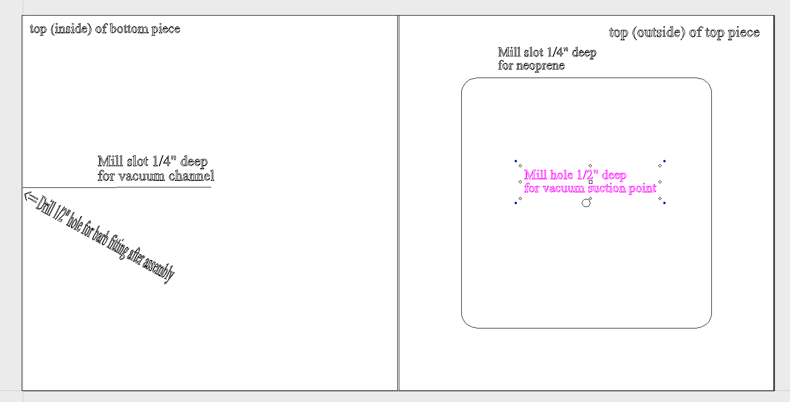
I presume the sandwich face between the two boards is a pocket manifold of some sort that connects the barb fitting / screw threads to the center vacuum hole? Is the connection as simple as a tight threaded hole in the edge for the fitting?
@JPlocher I’m not sure what you mean by “sandwich face”. These are one piece of 3/4” MDF. I use the Long Mill to pocket out the sides and the gasket groove. On my drill press, I drill a 1/4” lateral hole from one side roughly into the centre of the piece. (I use 1/4” because that is the largest bit that I have that is long enough.) I drill another hole from the face to intersect that hole. Finally, I counterbore the lateral hole deep enough that the face of barbed fitting tightens on the MDF. The MDF is soft enough that the barbed fitting cuts its own threads. After one pass, I remove the fitting and flood the threads with thin CA glue. After that dries, I re-install the barbed fitting.
I bought the gasket material locally. It is not foam. It is neoprene.
Clearly, these are not fancy. They work, so I’m happy with them.
I presumed (or would that be ass-u-me’d?) that you made the puck with two 1/2” MDF’s that were milled with mirrored CNC’d grooves for the manifold and neoprene and a matching hole for the suction point:.
So I am about to replace my first 4x4 wasteboard setup which was based on the Sienci recs. I want to use the CNC to do all the cuts are you did. I also saw the GOAT video and my initial design was a carbon copy of that. However, I already have metric dogs from my MFT sytem so altered to make 20 mm / 96 mm spacing. I also added inserts for a AirWeights table that I can add and remove. I can tile them evetually and have four or at least change the position of the table. Unfortunately they’re spacing is kind of weird. The table is 23 3/4 inches with holes which are not equal distance apart on each side (4 holes, 3/8 to first >7”> 9”> 7”, 3/8” to other side). You can see what adding these inserts does - a whole lot of holes crowded together. So I’m still playing with it.
If the inserts are screwed in from the bottom to give clearance above, they tend to unscrew when the bolts bind.
If the inserts are screwed in from the top to avoid that problem, the likelihood of hitting them with a bit approaches unity.
With the clamps I have, the insert spacing is often “just a smidge too far”, and I end up using spacer strips to bridge the gaps…
… which turns out to be a good thing because I no longer run quite as many bits through my clamps!
I started with t-bolts and extruded tracks, but never got to like them due to clamp heights interfering with dust collection and safe-Z travel. They feel unnecessary with an AirWeight system…
I have a “one large sheet” GOAT board that requires rotation and tiling to reproduce. I’d like to migrate towards a modular version, but don’t want to sacrifice the Z-height for a combined base-board+waste-board stack. I presume one could tap screws into the AltMill’s aluminum runners and screw the modular waste-board down into them, but I’m unsure if the wall thickness of the extrusions will provide sufficient tap engagement. What is your experience?
At some point I want to experiment with a 90˚ vertical stock holder (see Altmill with vertical board), so a modular baseboard system will be important.
Approaches unity - lol. I realized I can’t actually cover the whole 4x4 bed with one sheet of 4x8 because both dimensions are over 4’. Maybe I’ll put a second sheet to cover the remaining part of the table. I’m not sure it really matters. I do like the extra table space so I can put things on my CNC bed for the gantry to whack and throw on the floor.
I found that adding a 8-10" front overhang makes a really nice and safe surface for a tablet/laptop, game controller or keyboard/mouse.
It is a bit fiddly to keep alignment precision, but tiling with VCarve actually works quite well. You could build up a board for a 4x4 with 2 ~26"x~60" (or whatever the public-math-fails-me numbers are) sheets done in two tile passes each, and then glue them back together with biscuits - should be more than good enough and strong enough…