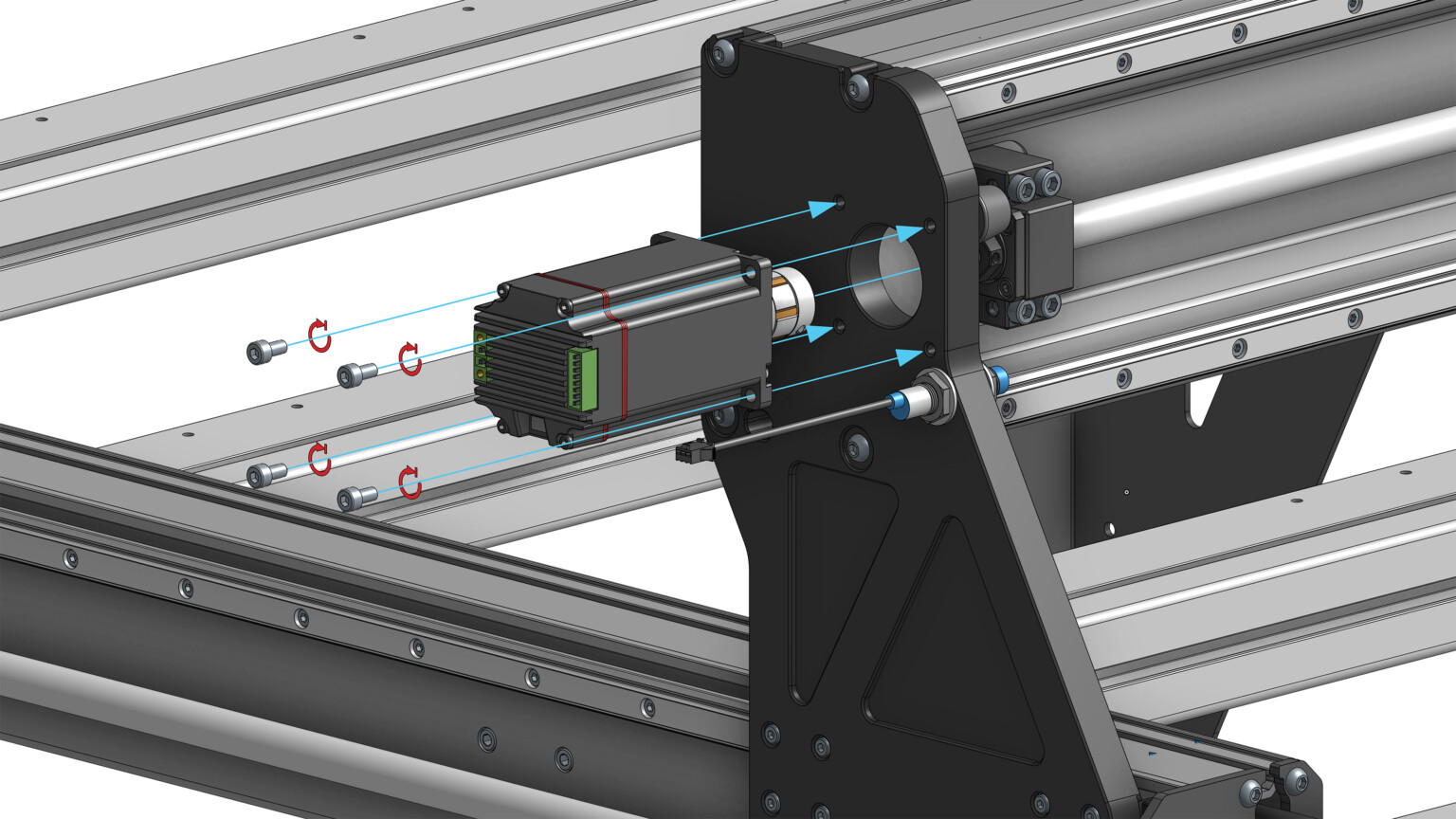
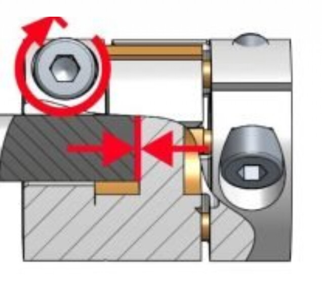
When test fitting the motors none of them will sit flush. They are off about 0.5mm to 1mm resulting in the motor being able to wobble ever so slightly. I’ve verified the coupler is inserted completely but when I try installing it on one of the ball screws there is slight gap such that the motors aren’t flush against the gantry or end plates. I remove the coupler and they will sit flush. Also verified the plates/gantry is completely flush and installed correctly. Attached picture from manual of what I am talking about.
Is there some other adjustment not mentioned that can be done?
I did contact support but was hoping someone might know what the issue is so can continue putting it together. Am concerned since assembly instructions specifically say it has to be flush or the motors might be damaged.
@DavidB Is this for the x motor only or Y1 and Y2 as well?
If it sits flush without the coupler, the coupler is what I’d investigate. I don’t remember but does the hole on the coupler go all the way through? If not, maybe the shaft bottoms out, preventing the motor from sitting deep enough.
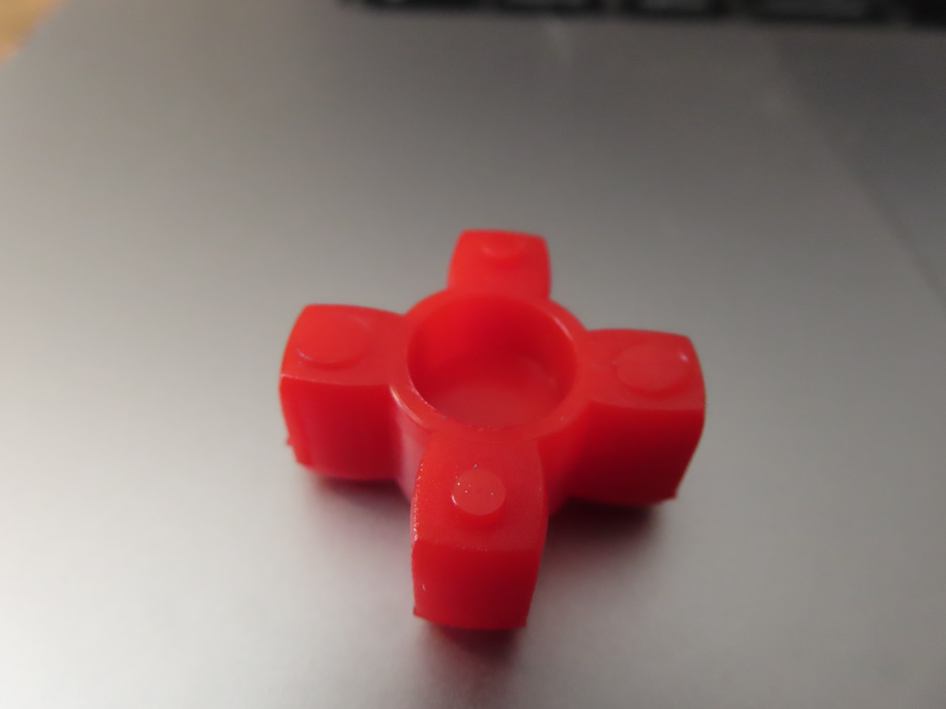
I tried all three motors with couplers on the x motor location and tried the Y2 location as well. Both were not flush by about 0.5mm - 1mm. The couplers look exactly like what are shown in the assembly instructions. The couplers have what looks like a piece of orange plastic integrated into the coupler in the middle restricting the motor shaft or ball screw to only go about half way so it isn’t open all the way. The plastic is drilled out so that only the center has thin layer of plastic preventing the shaft from going past the midway point of the coupler.
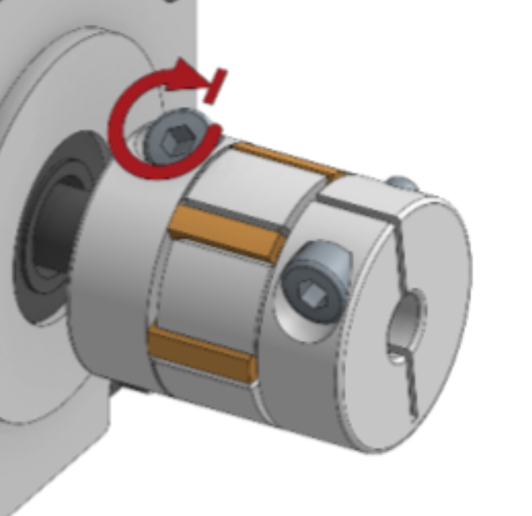
I do not recall ever having an issue with the motor not sitting flush. Take the coupler off and try the motor without it. That orange plastic (spider?) is primarily there to do the actual coupling so you don’t have metal on metal. The middle section preventing the shaft to go past the middle is a side benefit (you do not want the shaft past the middle)
I don’t quite remember but the center section of the motor face is raised and has to slide into the hole on the plate. That is probably a mm. Are you sure that the motor fits into the mounting hole properly?
@DavidB If you install a motor without the coupler, how much of a gap is there between the shaft and the ball screw? If that gap is inferior to the plastic “spacer” in the coupler, then the motor will never sit flush without some sort of mod. I wonder if the ball screw can move laterally at all.
The motors sit flush without the coupler. I will have to measure the distance between the motor shaft end and ball screw end. Just strange that they don’t fit on the X or Y locations by same amount. The center section of motor does have raised section that does appear to fit into the large hole in the plate.
A question for AltMill owners. Is the opposite end of the ball screw shaft adjustable at all? Wondering if it’s possible that the whole shaft is somehow too far towards the motor side. It’s hard for me to tell from looking at OnShape.
@DavidB I’m assuming that both sides of the coupler are loose when you mount the motors.
I do feel a little roughness on the face of the end of the ball screw shaft around the outside edge. Not sure if it is enough to keep the motor on the Y axis from sitting flush. I don’t see anything I can do especially on the Y axis since that is all one piece unless the coupler is messed up or something off with the ball screw. Really seems like only option it to try filing down the end of the ball screw shaft a bit at least to make it perfectly smooth but will wait for Sienci support.
Sienci support did reply and asked for video but not heard anything more.
Unfortunately my battery died on the digital caliper. The depth of the orange piece itself is 10mm . I did notice after taking it apart some of the legs on the orange plastic have small circular feet on MOST of them. Two of the legs on one side have the feet flush which seems odd. Does yours have that or is it completely flush on both sides?
@DavidB Not sure. I measured the depth on both sides of the coupler with my caliper (14.5mm on both sides). Subtracted 29.0mm from the total thickness of the coupler. That gave me 1.5mm for the “spacer”.
I’m assuming all Altmill couplers will have the same dimensions.
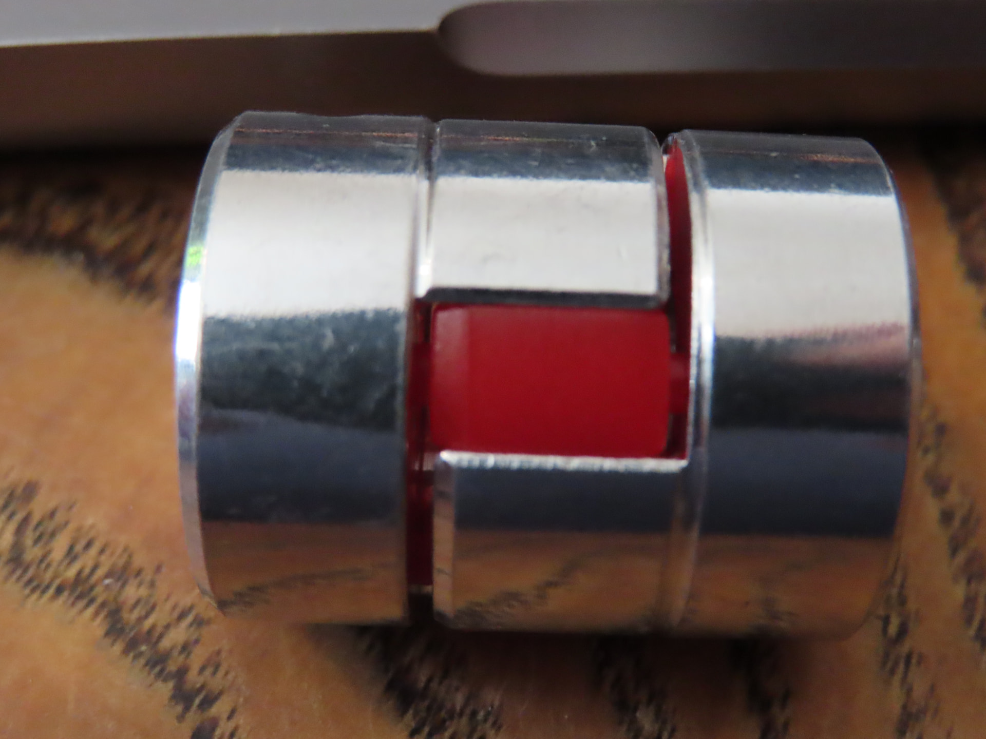
Here is the circular feet I am talking about that is keeping the two metal ends of the coupler from being in contact from each other which how yours looks?
As a test I mounted the motor and coupler without the plastic piece and everything does sit flush but obviously won’t work that way.. so something with the plastic is pushing it out too much.
The assembly instructions do appear to show the feet and separation between the pieces so only thing left is either the roughness of the ball screw end or thickness of plastic between the two shafts.