Attack of the 3D printed robots


No, not those robots…I’m talking about these robots!

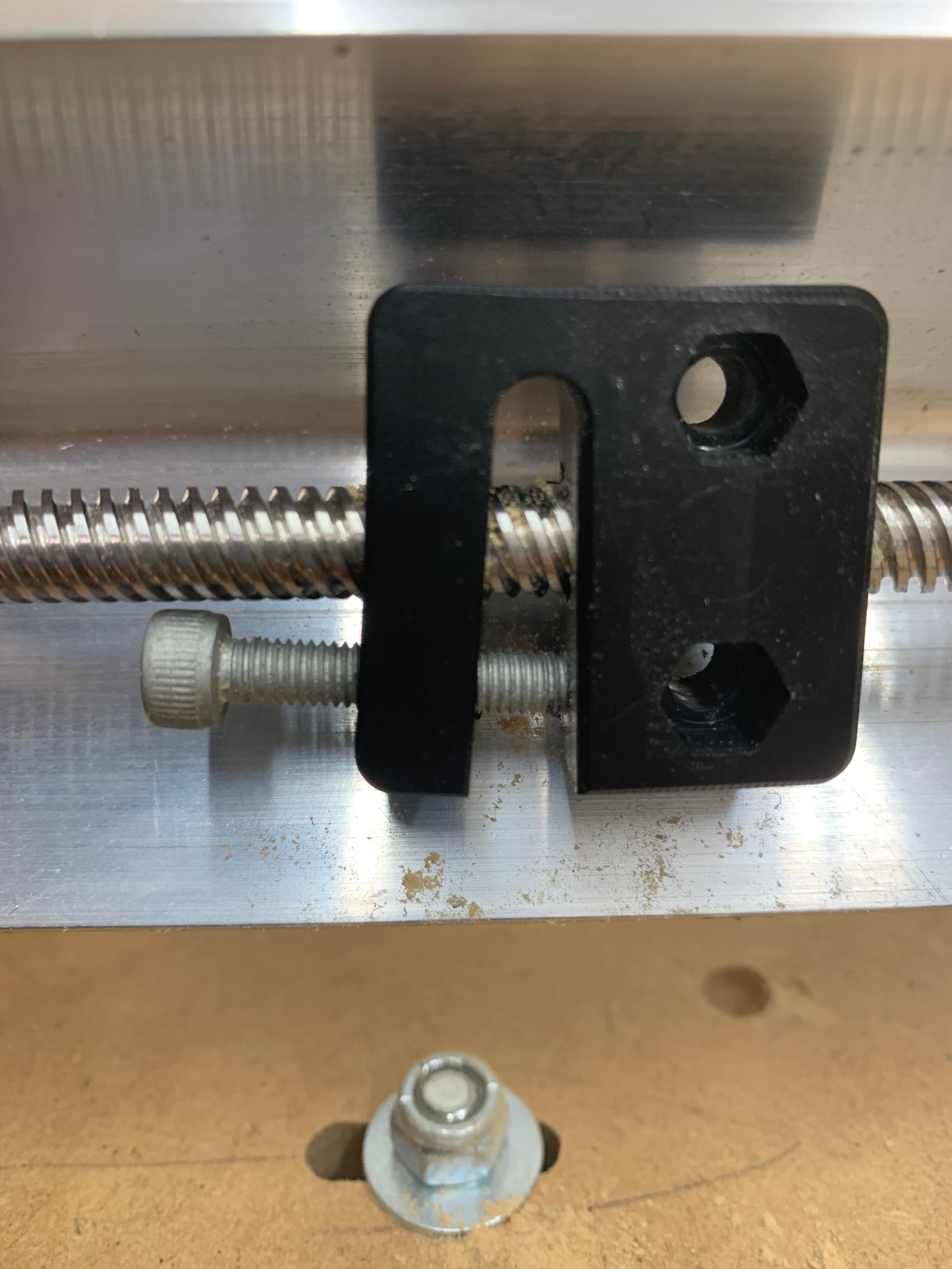
While recently doing some maintenance on my LongMill Mk1 and installing a SuperLongBoard I discovered that my X and Y anti-backlash nuts were pretty worn and the adjustment bolts would soon hit my lead screws.

Annoyed with myself that I didn’t include them in my SLB order I decided to see if I could print some. So knowing that Sienci open sources a lot of stuff I headed to OnShape to get the stl for the ā€œrobotsā€.

What! These don’t have any threads! Maybe Sienci figured nobody would hide the lead screws and look in there? Or maybe that is all they need because they tap the holes?

In any case OpenSCAD to the rescue! Just need to make a lead screw and M5 tap to thread the blank and then we can try to print some. The only materials I had on hand were PLA and PETG filaments. I think that out of those two PLA is likely the better material considering hardness and coefficient of friction. Polyoxymethylene (POM), named Delrin by DuPont would be the obvious choice, and is what Sienci’s are made from, but I didn’t have any and it’s hard to print. More on that later.


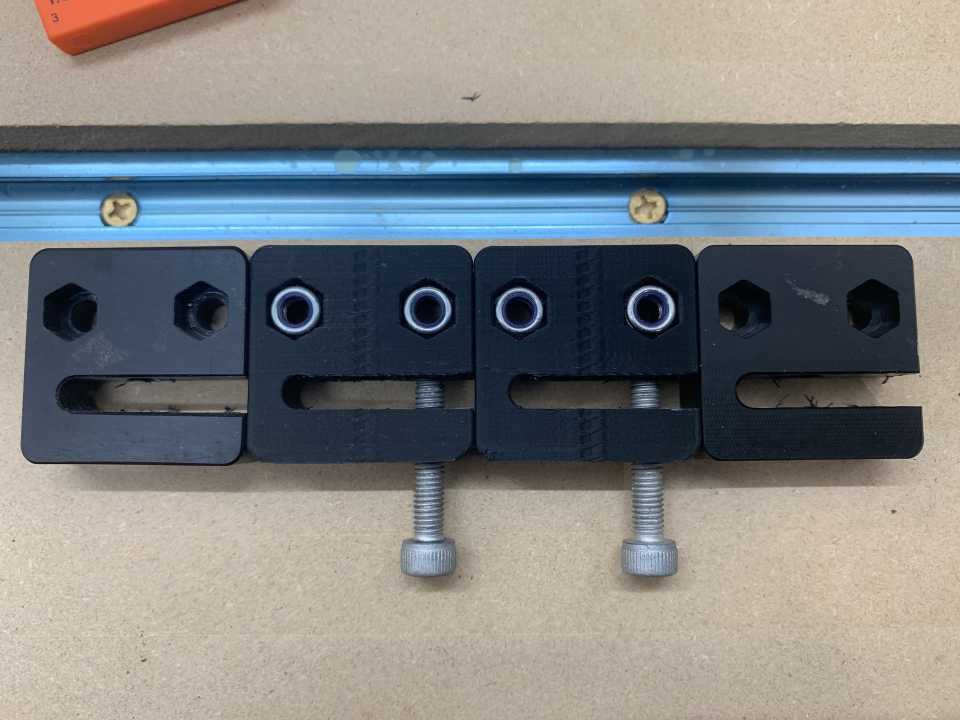
Here there is one of my old ones on the left, with his jaw hanging open in awe of the PLA printed twins in the middle. The last one on the right is the spare that came with my mill.

Okay, so do they work? I installed them and jogged slowly. All is good! I increase the speed and suddenly one Y motor stalls and the X axis is now askew. What to do? Well I reset the Y alignment and sprayed the lead screws with Blaster Dry Lube with Teflon.


This is my favorite dry lube out of the ones I’ve tried. Doesn’t even look like you put anything on the screws after it dries.

With the lube and loosening the robot mounts and jogging around then tightening them back up to make sure they were aligned properly all is working well. At least so far. I believe that the printed robots will only work better as they wear in and smooth the load bearing surfaces.

I have only done limited testing with the PLA robots and place this firmly in the ā€˜do at your own risk’ category. Whether these are a ā€˜use as a last resort until I can get some real ones’ or a viable alternative remains to be seen.

In the meantime my roll of POM has arrived! Alas I haven’t been able to get a successful print with it yet. I doesn’t like to stick to anything I’ve tried so far as a print surface. I’ve tried smooth and textured PEI, blue painters tape, glued down paper, all with and without glue on top and I can’t get past the 2nd or 3rd layer before the extreme warping pulls it from the bed. So POM is still a work in progress and I’ll update with my progress, or lack thereof, with POM at a later date.

If anyone, especially Sienci Labs personnel, has a reason why this is a super horrible idea I’d like to hear why. I’m not trying to hurt myself, others, or any CNC machines. Again, I’m not even suggesting that anyone try this but I am going to post the STL and OpenSCAD files for this print for the adventurous.

T8_Anti-backlash_Nut.zip (233.1 KB)

Inside the zip file file is the T8_Anti-backlash_Nut.stl and an openscad folder that contains the original model and the OpenSCAD file used to produce to threaded model. There are two ā€˜fit’ variables at the top of the file that can be used to adjust the fit of the screws. I printed just the ā€˜jaw’ until I got ones that fit well to save time and materials. I used a 0.6mm nozzle with 4 walls, 6 floors and ceilings and 40% infill. I used a 0.1mm layer height to try and minimize the layer lines and get the threads relatively smooth. I also used a support enforcer to put support in the mouth only.

6 Likes

Oh the magical world of 3D printing. I am still to enter the gates that keep me away from producing my own robots and I am unaware of how mine are fairing.

I am noticing a growl lately from behind the door when the machine runs, so it might be time to open up some robotic mouths to make everything run smooth again. I have not done anything to them since their initial installment about 2.5 years ago.

Have you adjusted them a lot before this total replacement? What’s the trigger to do so?

Tnanks for the creative story telling. I like that.

2 Likes

Those of you that haven’t gone down the rabbit hole of 3D printing - you haven’t got a clue of what you are missing! Sure, it can be frustrating at times and yeah, it can waste a lot of time but my world would not be whole without a 3D printer.

3 Likes

@Jens I agree with what you said about 3D printing. I had my printer first and it does open up so much. From silly toys, to fixing things you would have thrown away because of that one broken plastic bit. Endless brackets and organizational bits and bobs, the list goes on and on.

I think one thing that might surprise CNC users that don’t have a printer is the vast quantity of models that you can get for free. You can print so many things without being a designer. I haven’t found anything close to Printables or Thingiverse for CNC routers, at least in terms of quantity.

All in all I think the barrier to entry is lower for printing than CNC. The software pipeline isn’t as complicated but there a ton more knobs to turn for advanced users. Usually some sensible defaults that come with the software will go along way.

@Spamming_Eddie This is a highly technical procedure so buckle up, my friend! Every so often I’ll grab a steel plate that has V-wheels on it and try to wiggle it back and forth on the lead screw. If the robot needs adjusting you’ll feel and can even hear, if it’s quiet, the play. We are talking about modest force and the wiggle is sub millimeter but if you feel it just tighten the bolt a bit. It usually only takes like a 1/16 turn or so and the play is gone.

If I suspect that maybe someones machine is jamming because of an overly tight robot I’ll suggest backing it off until they can feel the play and then slowly tighten the bolt. Just in case your not aware I’ll also say the other issue they sometimes have is being mounted slightly crooked due to ā€˜bolt slop’, another highly technical term I like. If they are a bit crooked they will tend to bind toward the end of the axis where the lead screw doesn’t have the flex that it does in the middle of it’s span.


This is what my robot looked like after the gantry plate was rolled away. You can see how the adjustment bolt works by spreading the two threaded sections with the side affect of angling the bolt towards the threads. I’m guessing it doesn’t sound good when they start to rub.

Side note: That bolt isn’t bent but it sure looks like it to me! Funny how our brains struggle with certain things and produce optical illusions!

1 Like

Thank you Michael, for that elaborate and ultra detailed explanation. I do have a bit of play, but feel it’s the makita that is a bit wonky. I workaround by pocketing from the inside out and run cutouts with a spiral down toolpath. This way the slop wont translate in an engagement wonk at the starting node. I’ll start pulling tomorow to see if I can feel and hear the wonk at the axis.

My initial reaction, adhd-reading your post was ā€œbetter get me some shorter boltsquirrel!!1ā€ and I’m ashamed for that. I am however gonna get me some shorter bolts! I will make my bots look like :grin: before I allow them grumps to retire.

I have entertained the idea on investing into a 3D machine alongside the mill, but after some cooldown period I reasoned against it because having my full attention with one steep learning curve is hard enough for me as it DUCK!!1

1 Like

Yeah, a couple of minutes with a hack saw and I wouldn’t even need to buy the bolts! But look at all the fun I would have missed out on! :laughing:

In all seriousness you can probably extend their life by a good bit that way. Mine lasted almost four years as it was, not that I use my mill every day.