SLB upgrade, mill remounting and more!

Warning

This is going to be a long post. Better take care of any pressing issues and come back with your favorite beverage. Go ahead, I’ll wait…

Preface

I recently ordered a SLB for my LongMill Mk1 30x30 and I thought that it would be a good time to do some maintenance and various other things I’ve been putting off. Here’s the list of things I had planned.

  • Install the SLB.
  • Remount the LongMill on MDF strips to raise it and make squaring easier.
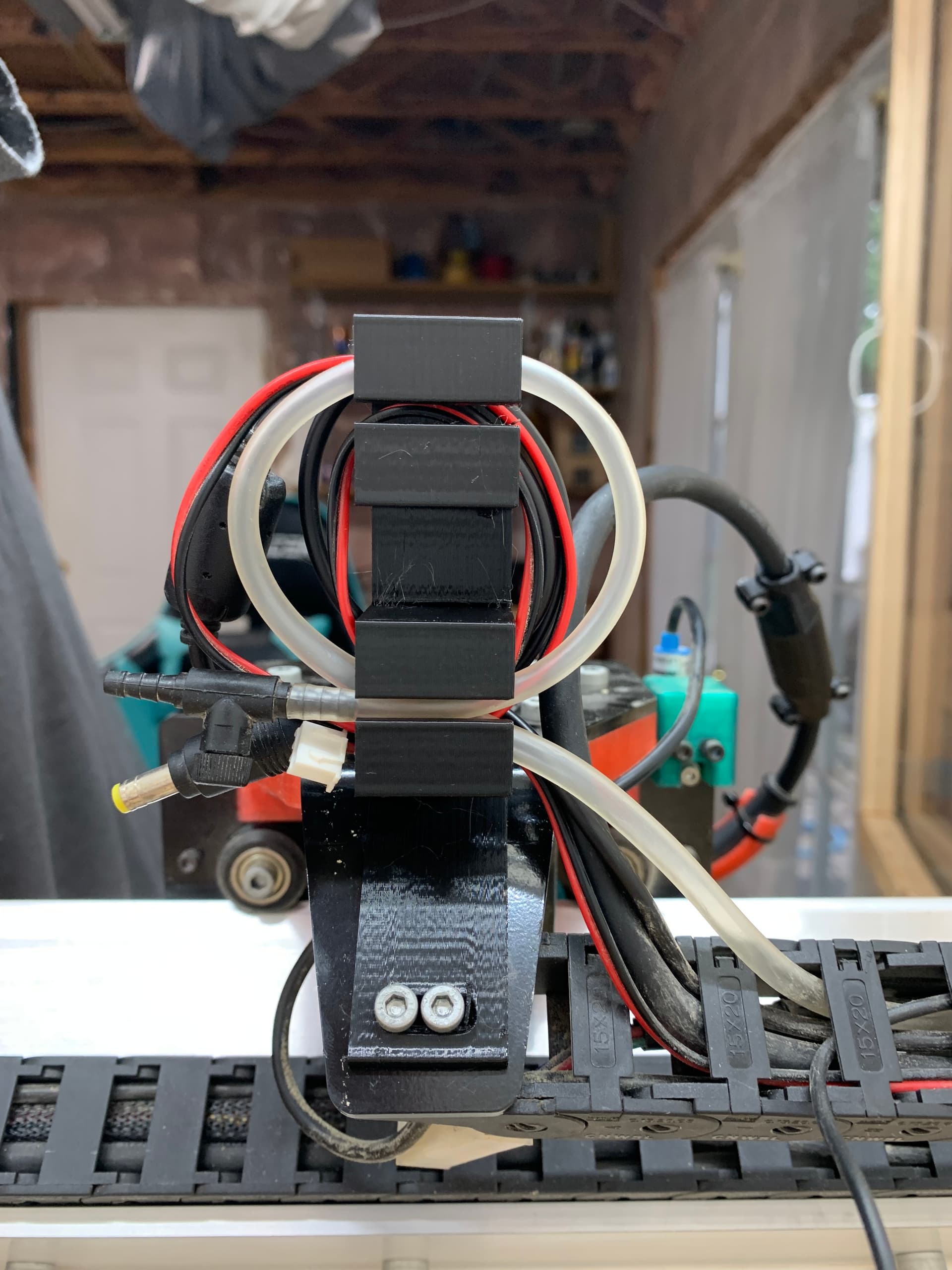
  • Redesign the inductive sensor mounts to gain a little more machine travel.
  • Make a new spoil board, possibly with a different clamping system.
  • Inspect the machine for any problems while I had improved access to various parts.

Super Long Board

Starting with the SLB and what can I say? It’s plug and play, easy peasy. After installation I restored the defaults for my machine and then changed the things specific to my build. I needed to flip the X axis because I mounted the motor on the right, turn on sensors, etc.

Disassembly

I decided the easiest way to break the mill down was to unplug or dismount the electronics, remove the bolts to the two anti-backlash nuts for the Y axis as well as the lower V-wheels. I set the eccentric bolts to their loosest position before removing the lower wheels. I was then able to carry away the X axis.


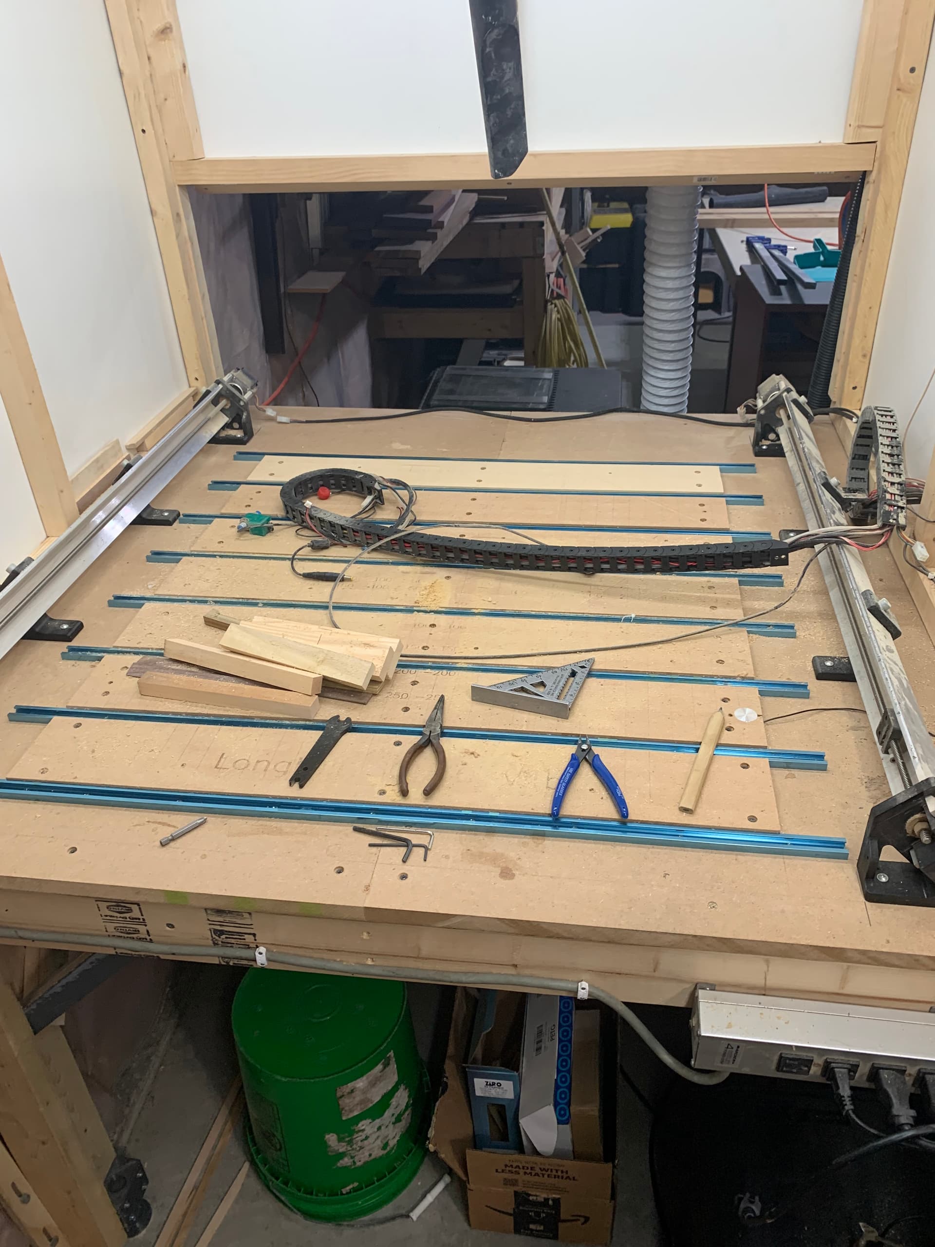
After that I just needed to disconnect the drag chain and remove the Y axes but first I marked my table with the locations of the corner feet.

Lift Kit

In the four years I’ve owned my LongMill I’ve learned a trick or two, mostly from the folks on this forum, thank you very much! Since the first time I saw it done I thought that mounting the mill on MDF strips with slots and then bolting it to the table was the way to go. Of course this was shortly after mounting my mill and it seemed like a lot of work when I was already under a millimeter according to gSender and my measuring skill.

I figured that if raising the mill by one strip of MDF was good, then raising by two would be even better! I had my router mount in the top position and if I moved it down it would compensate for the added thickness. But maybe the people that do this method already use the lower position? Oh well, full speed ahead! I glued up some MDF and mounted the rails using some clamps to line up the feet on the inside edge. Oh, yeah, I had cut the strips and milled the slots before taking the LongMill apart. Whew! That was a close one. I also remembered to drill the holes for the bolts in my table before the rails were in the way. Dang! I’m good!

Squaring

With an existing hole that I need to line up with, gSender’s squaring tool wasn’t going to be of much use. If it said to move one rail 2mm, would I need to move one by 1.5 and the other by 0.5 to end up square to the slot? I guess I’ll do it like a caveman spaceman hybrid, with a square and a laser!


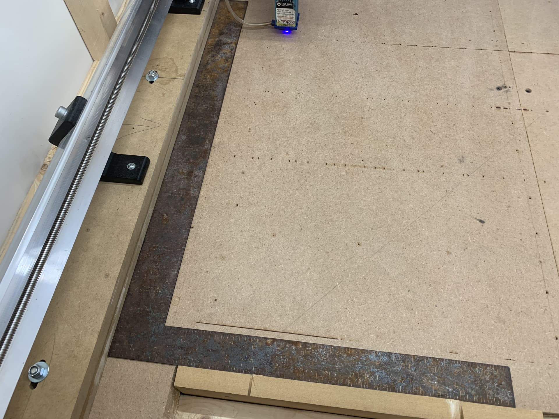
Using the square I assembled the mill and left the bolts loose. I clamped a piece of MDF in the vertical mount to square against.

I then kept running the laser up and down the Y axis making numerous small adjustments to the left rail. When I was satisfied I tightened up the bolts on the left and then fired up the laser to double check. By the way, I always wear my laser glasses and I have opaque ā€˜curtains’ that I pull to protect anyone passing by from eye damage.

After that I repeated the procedure for the X axis moving the right rail back or forward as needed. I then lightly fastened the front bolt, jogged to the rear and tightened that one and so on to get the width right.

Then I burned a square with the laser to check. It’s square enough for me!

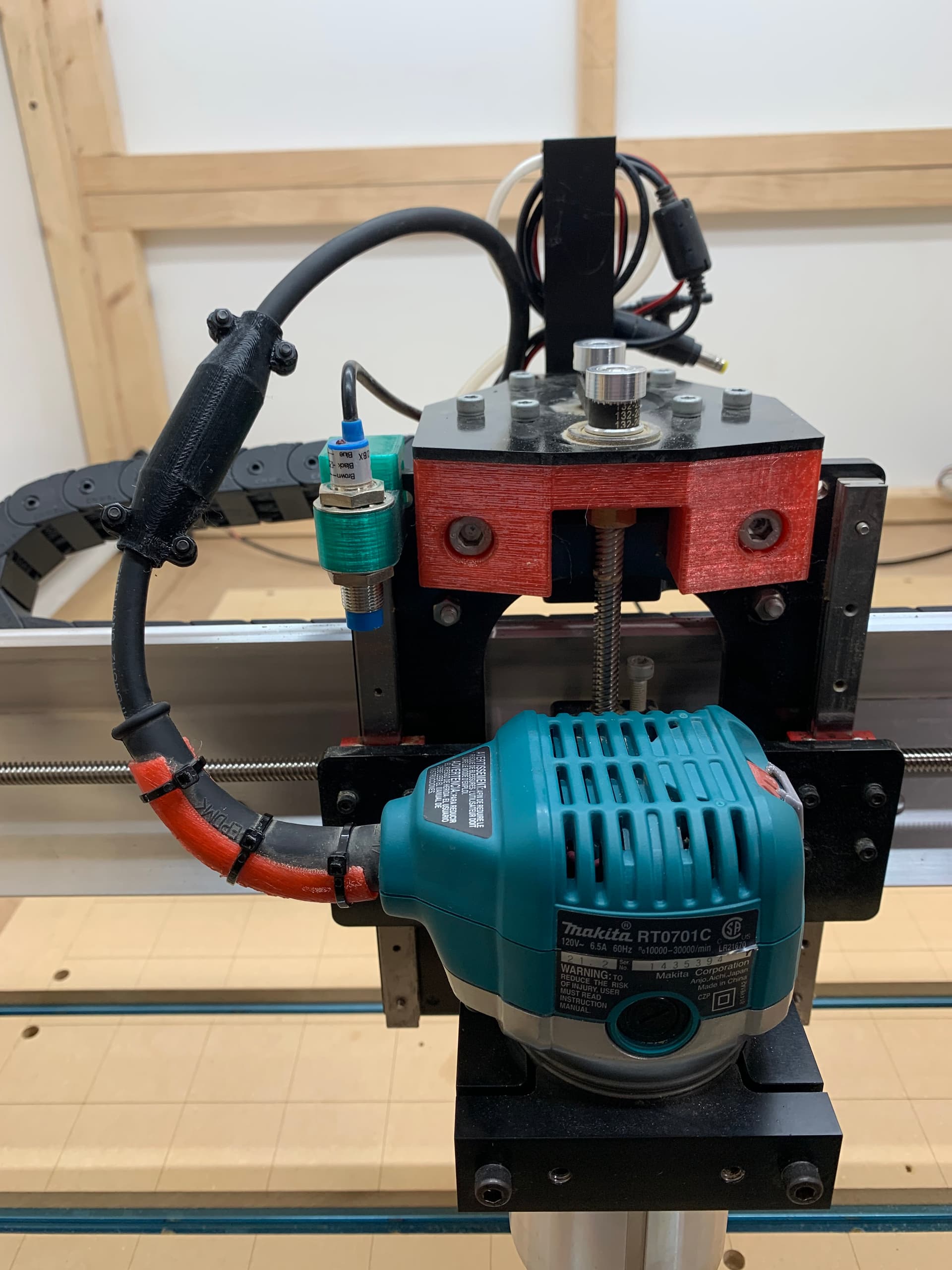
Inductive Sensor Mounts

I think I lost 10-15mm of width with Sienci’s mounts for the Mk1. A little less on the Y. With my largest project so far not coming anywhere near close to the maximum dimensions of my mill it’s imperative that I regain as much of that space as possible!


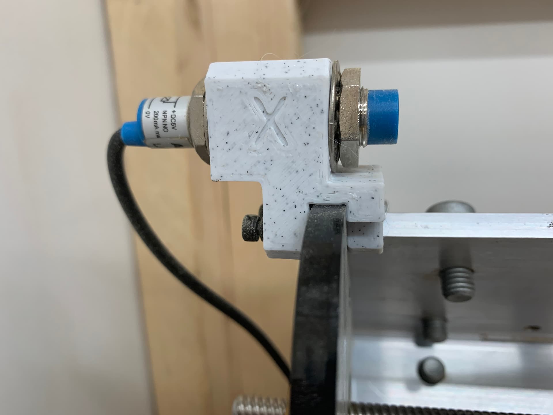
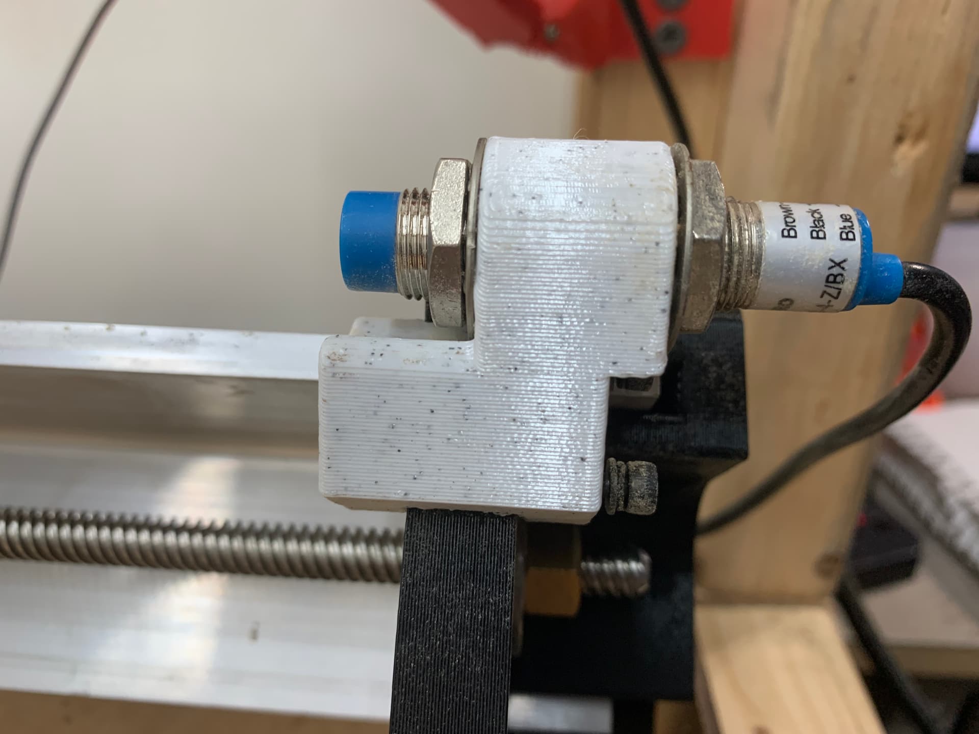
The Z mount was fine and there wasn’t any travel to be gained there. I ended up with [793, 838, 104] for my travel limits.

Spoil Board

My spoil board lasted almost four years but was getting a bit on the thin side for my taste. Watch the same video that I did if you want to learn how to make your spoil board last.

I ended up going with the same T-track design that I had for my spoil board. I couldn’t come up with a reason to change it.


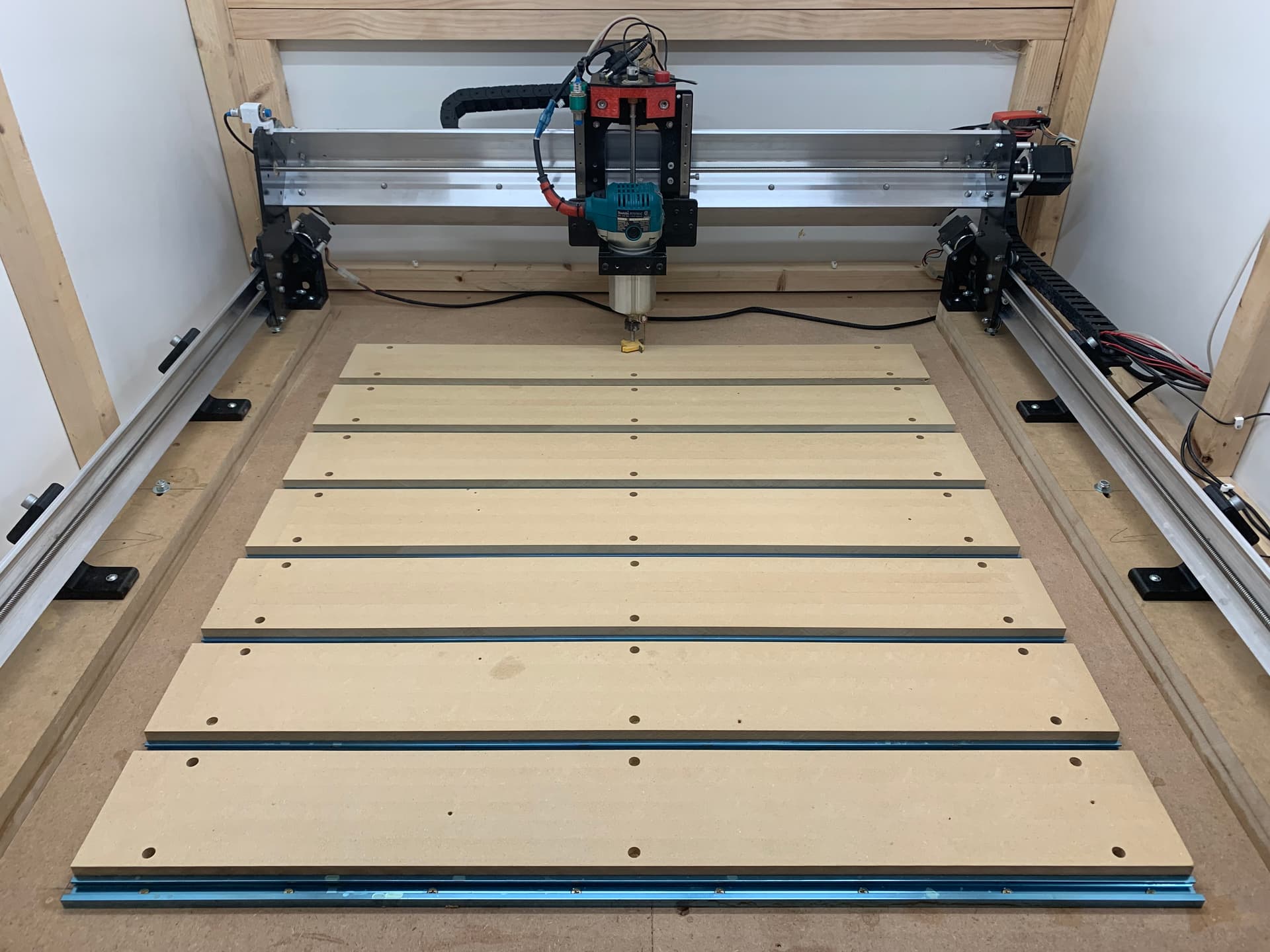
OMG! What have I done? I can barely reach my spoil board! Is this my demise? Okay, I settled down after awhile, that was the whole point wasn’t it? It’s much easier to raise my work than the mill if needed. It’s not a problem until it’s a problem.

I have a DIY cyclone thingy on my vacuum that I reviewed here. Okay it’s more like a link to a video than a review. Before I surfaced I cleaned out the bucket to show how well it does on fine MDF dust.


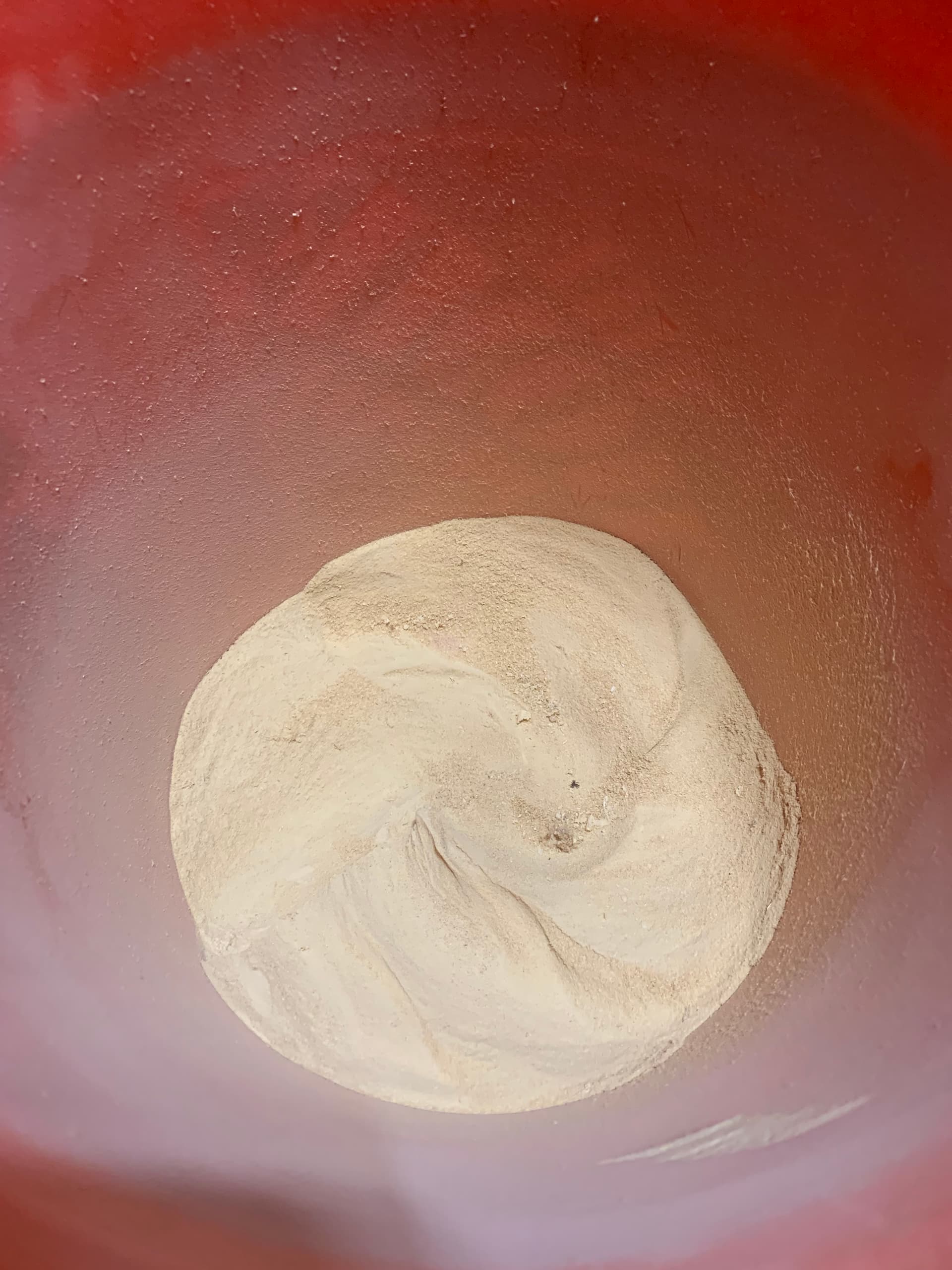
Looks like a tornado hit a sand dune in there!

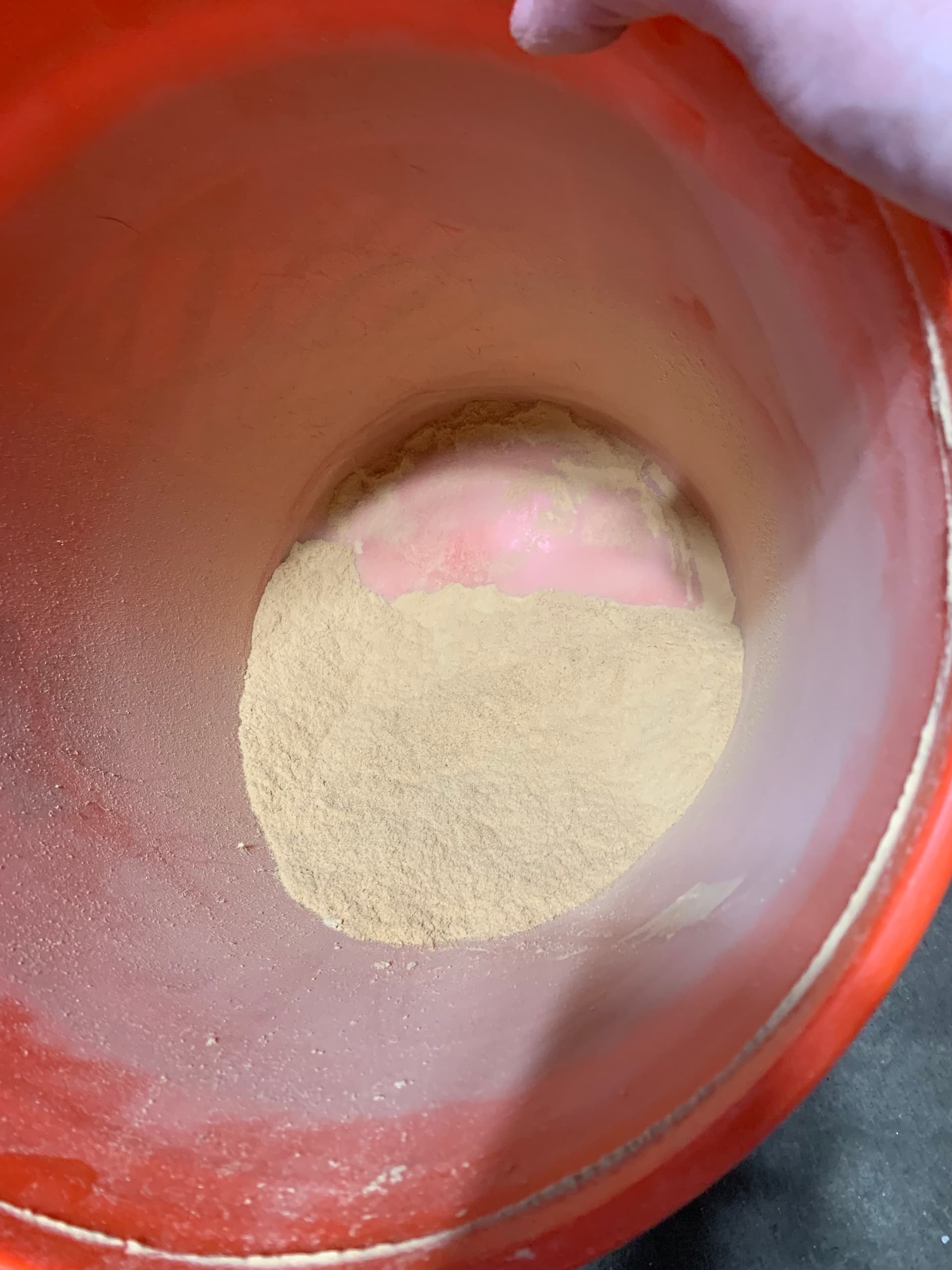
Seems like it catches quite a bit. I should have emptied the vacuum bag so I had some sort of percentage. Dang! I’m not THAT good!
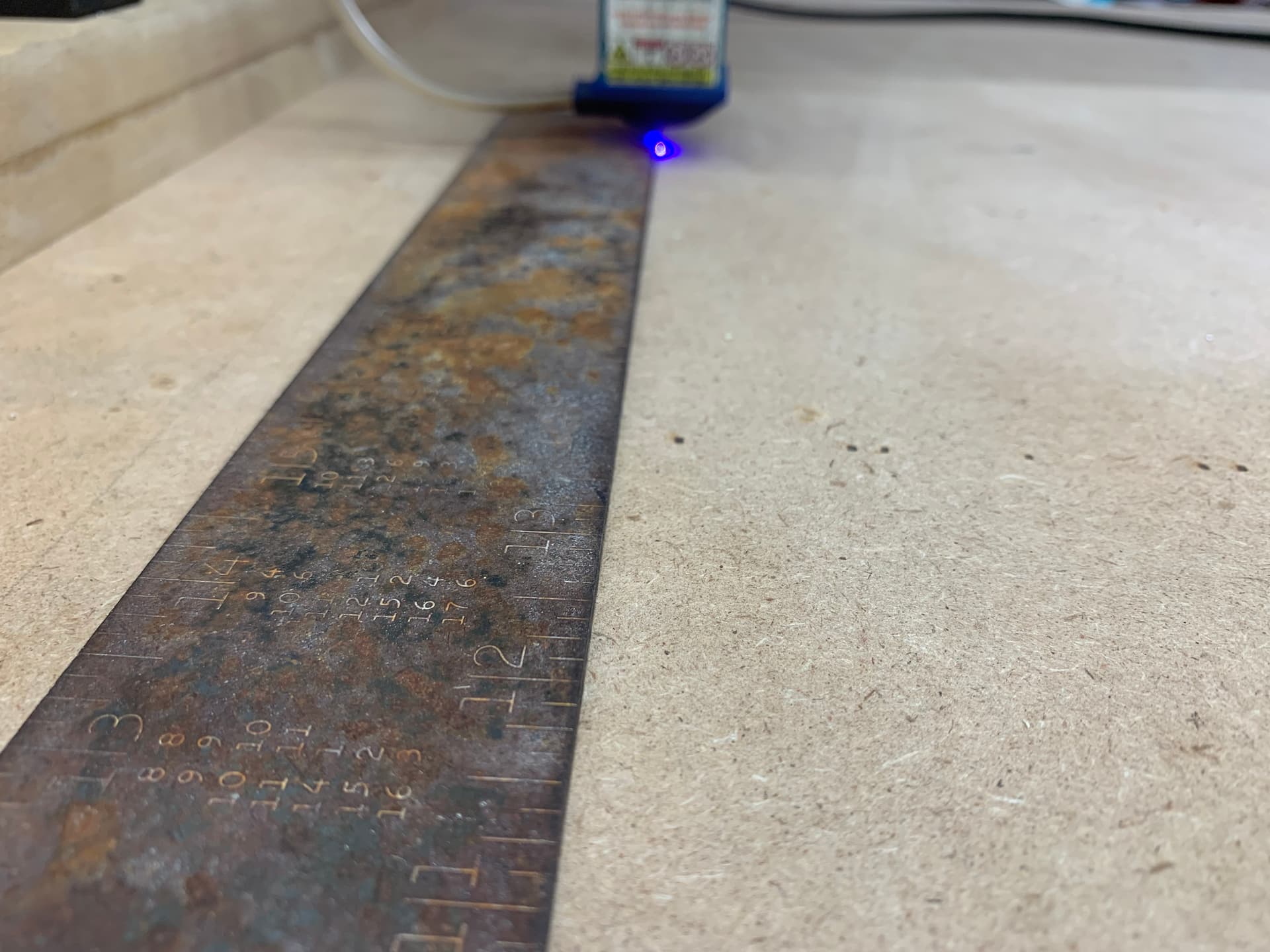
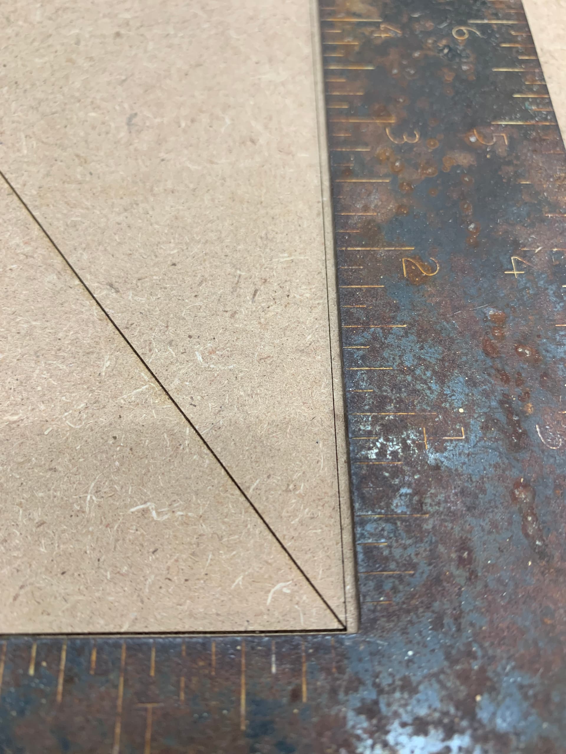
Laser Grid

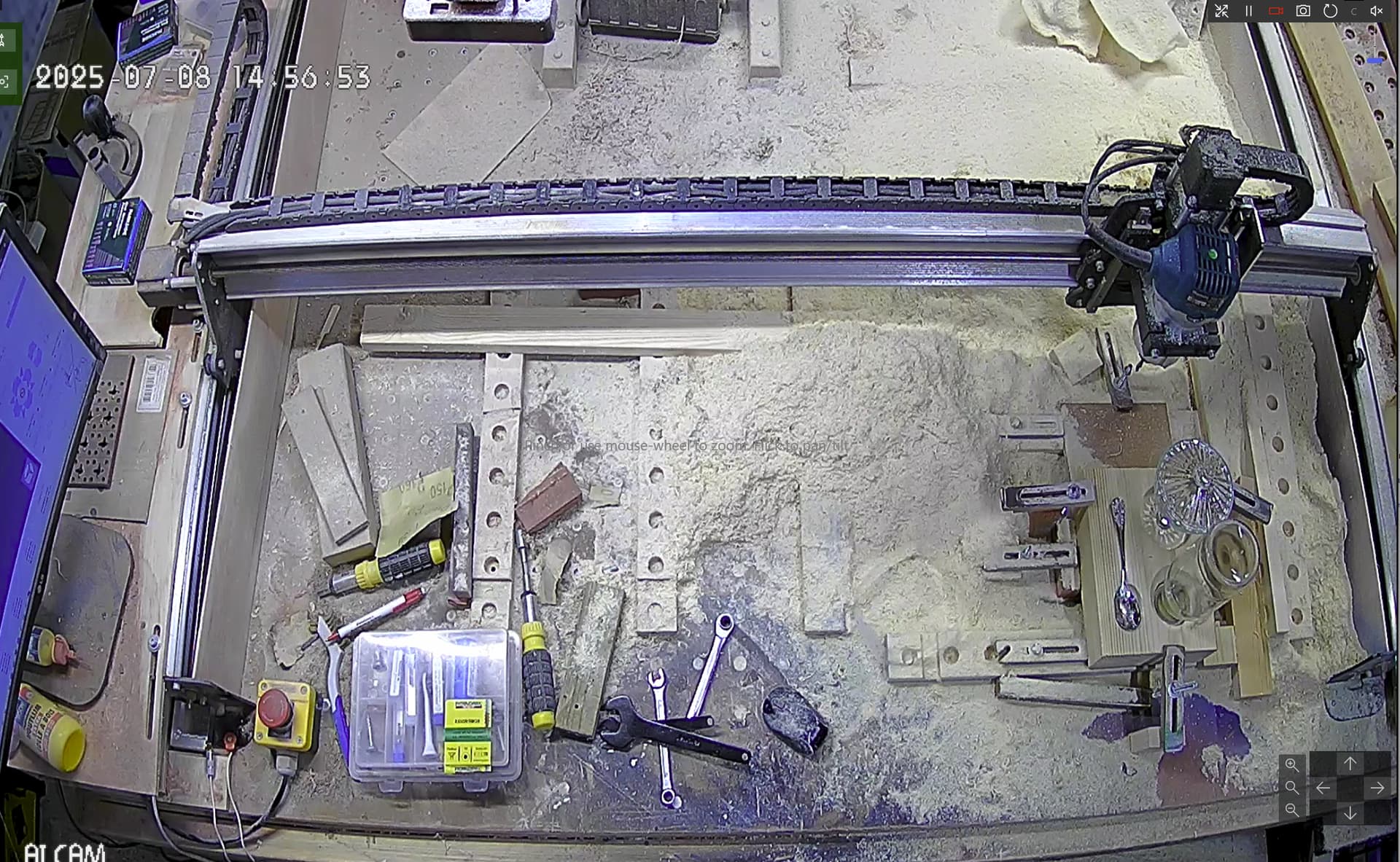
I like a nice grid on my spoil board so that I can quickly get things aligned. I had to make a new mount to reach from way up here. I had made a small dot with a V bit in the center of the board so I had a mark to align the laser.


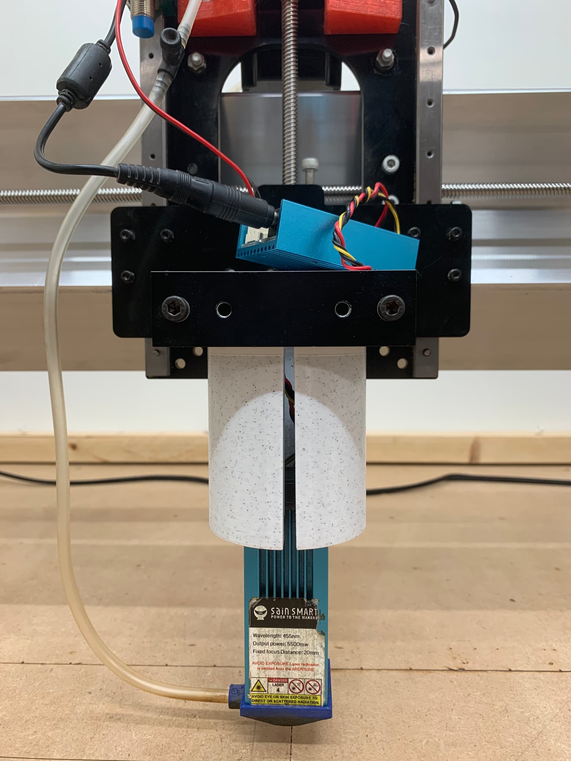
It sure is nice to have that router out of the way for this bit.


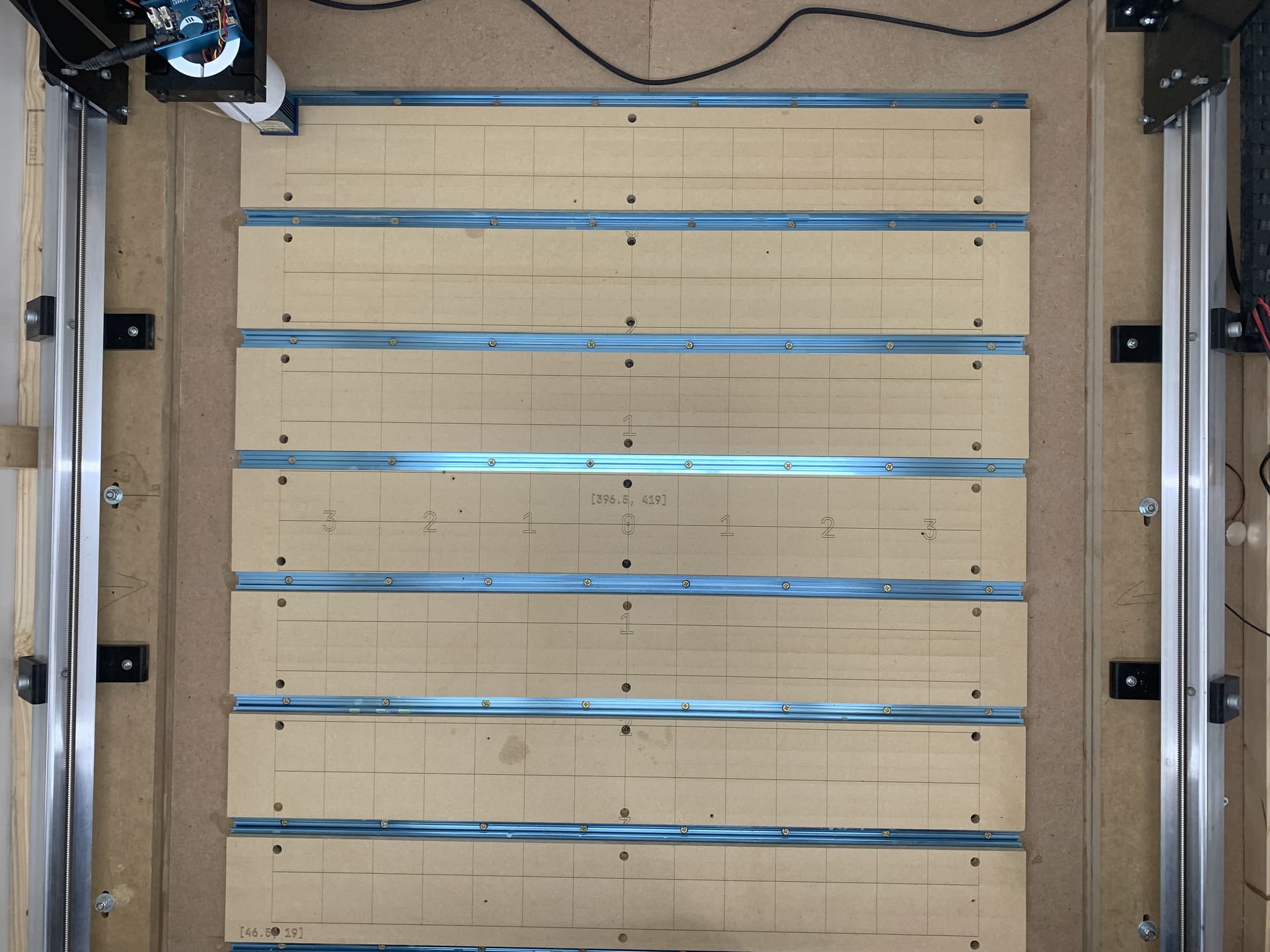
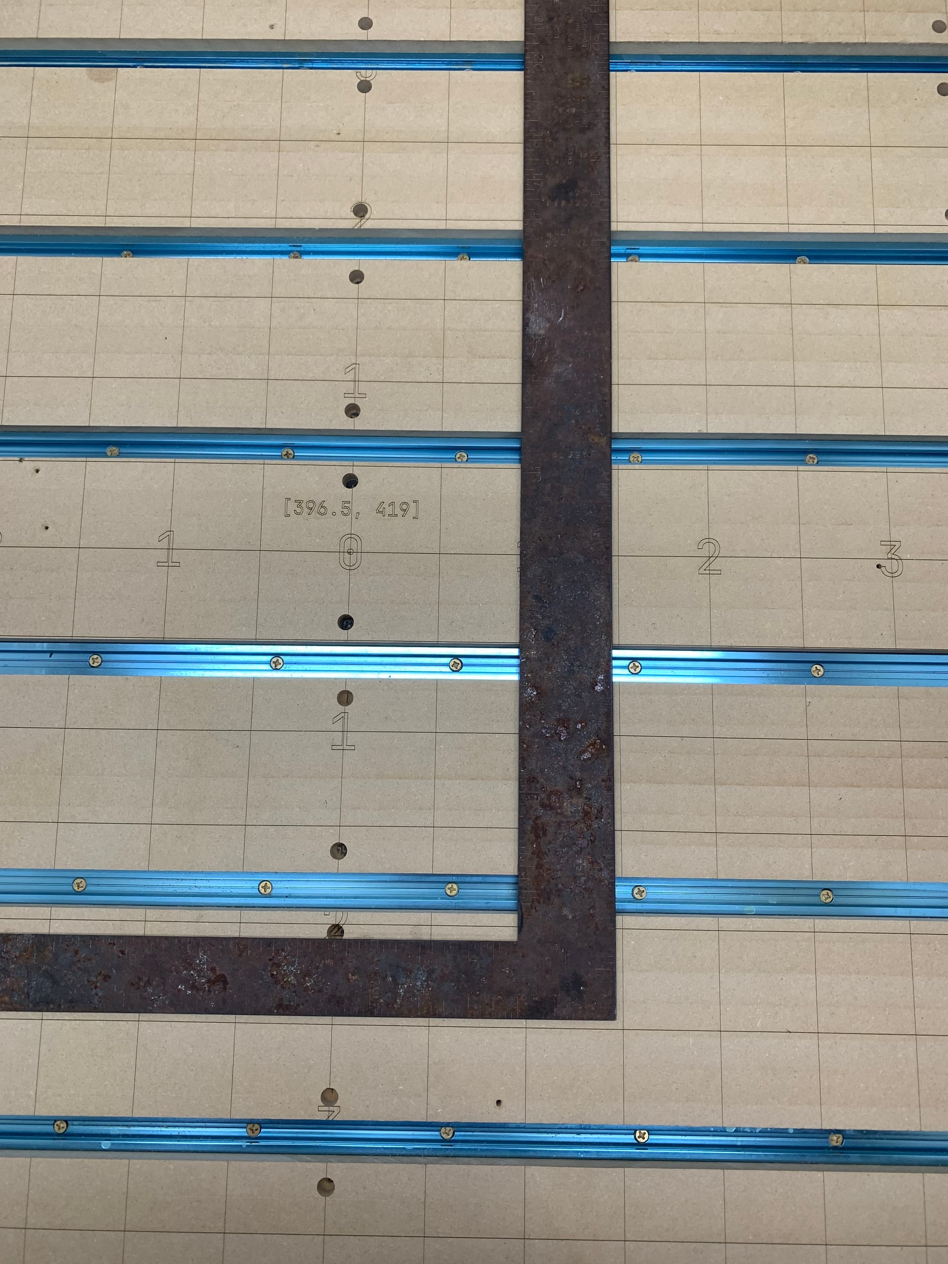
It’s good enough for the work I do! The bracketed numbers are the machine coordinates for getting to the lower left or center of the grid.

Wrap Up

Along the way I discovered some worn anti-backlash nuts. There is a shorter novel about that over here. I also discovered that my linear bearings on the Z could have been better lubricated. When I had the router mount off to move it to the lower position they were free. I lubed them until they fell to the bottom by their own weight. I need to remember to lube them a bit more often.

If your still awake, thanks for reading my book! I think my LongMill is ready for another four years! I should probably go and make something already…

7 Likes

Slams Moggo coffee on the table, grabs a rando keyboard from a shelf and starts typing:
ā€œWhat screen does this one connect to?? Ah there you are.ā€

My lawn Michael, that was an epic adventure and I know you must have left out some colourful language, but no worries I have inserted that in my head, cause I like my Michael stories at least.. twice as long.. A total makeover like that does not succeed without being cemented with.. lets call it Poetic freedome, shall we?

Oh look at that extra z clearance you got going there. yeah that’s the way to go. If I ever will take my reconstruction path, I will implement something like that too and add some. My wastejig setup screams for more cleareance. I will try to construct the complete machine with cleanreance on some industrial "drawer"sliders I have lying around, and create a tiling/vertical/beer barrel milling option. It’s going to be poetic! One day.. sweet future.. waaaywayway then.

I love your setup. It’s so clean, smooth, neatly gridded. If I’d take a snap of the millcam right now you’ll see a rather different picture. Ah what the heck, lets have a laugh.

Verry Christmassy ey?

Anyhooo, you know when people start with: ā€œI hate to beā€ and then add ā€œa whinerā€, ā€œa bleepickā€, ā€œirritatingā€, ā€œa knowitallā€ etc.. and then go on the be just that. I know for a fact that those people actually want to be what they say they don’t want te be. They do! How do I know?

I hate to rain down on your parade, but I have to drip.. or lets call it a drizzle.. a bit on your makita setup. I know You lot have only 120V kiddy power, but even that isn’t without its dangers. I am no saint, by a long shot, and have my own -secrets that should not be installed like that- around my home, but one thing you will never see me do is making an appliance partly disconnectable.

You see, a half connected router is essential no more than a well conducting bridge. And no matter how allergic I normaly am towards whatifs, when I see AMPs used in high power circuits, my brain produces a bunch of them and most have serious answers to them.

Let me do one: What if one of the amp connectors shakes loose during operation. You have either a unprotected conductor hanging on the cable side or one on the router side. A router that can be seen as a conductor when switched on.
I assume you have the life wire on the cable side as the protected female one, but that is only when you assume the outlet is wired correctly, the connector is wired correctly and there are no other appliances active on that line.

When there are so many assumptions needed to make something safe, better assume it is never safe and when you assume something is never safe, that AMP you see there is to be seen as an unprotected life wire hanging on a aluminum framed machine that is still running and about to shake rather violantly because the bit has just stopped milling mid program.

What are the odds?

I strongly believe that there are mondays out there that would love to have this opperunity.

At least install a 30ma differential circuit breaker on the circuit this router is on, but even better would be to have/3Dprint a wee more secure way to have this router disconnectable.

[/drizzle]

I get it though. It’s an awesome idea to have your router flexible this way. As is the whole setup you have going that has become even more versatile with that huuuuge z-gap you can fill up with wood chips.

Sorry for the wet floor.

1 Like

No worries about the rain! I’m glad you mentioned that and I actually had half a thought along those lines. I was thinking more about if I was using it off the machine and stepped on the cord or whathaveya.

I could have done it with a replacement plug but they are so big and bulky so I chose this way in my ignorance. I’ll take your advice and make it safer even with kiddie power. In my experience it’s not too bad when it just goes up one finger and down the other but across the ticker is another story!

The last thing I would want is for someone to copy something I’ve done and get hurt. I’ll go edit in a warning above or remove it until I have a safer solution to post.

I don’t mind if it’s somewhat harder but safer to take apart. I just don’t want to deal with routing through the drag chains on a regular basis.

On a lighter note, I did think of your jigs and how they might benefit from a tall boy setup when I saw the clearance I ended up with.

Thanks again for the safety concerns, they are always welcome.

Just double checked and I did do at least that much.

1 Like

I figured the bulky thing was the reason to go amp.

Maybe consider solar connectors. They are high voltage rated (often solar sets work with voltages above 400V DC.) click and lock in place. Are ip67 rated and work with female and male pairs that can be pokejoke poled to keep line and neutral wires on their counterpart. They are sleak, secure and cheap.

To seperate them you need a specific unlocking tool or be handy with a small flat head screw driver.

Though they are not ment for home appliances, I feel these will give you a way more secure connection that will not budge when you step on the wire, or shake them for 4 years on a mk1.

There are a multitude of connector systems available that can handle the current and voltage without being too bulky. They do tend to get pricey though …

That and there is a container of them in the shop. Its easy to use the wrong thing if you already have it!


So according to the box the blue ones are 16-14 AWG. A search says 16 = 13 amp and 14 = 15 amp.

Does 16-14 mean were kinda sure it might be able to handle one or the other? Maybe it just means it’s suitable for both wire gauges? Electrical really is a weak point for me. Are amps the only consideration when it comes to wire gauge? Or do they just give an amp rating and assume 110-120v and it’s the power that really matters. Maybe I should have used the yellow 12-10 ones, not that I’m saying AMP is the right connector. I didn’t even know that’s what they were called to be honest.

And the not wanted it to be bulky was because I figured it’d be less likely to get snagged on something. That thinking could be flawed, it wouldn’t be the first time that’s happened!

EDIT: The router says 6.5 amps so I’m guessing that the size of the connectors is adequate and I just need to add strain relief to make sure they can’t come apart accidentally. When I unplug it on purpose it’s not plugged in to the outlet. The outlet is on the IOT relay that Sienci has in their resource pages so that would have to malfunction as well to have power at the connector when the mill is not running. The switch on the router itself is always on.

Electricity is confusing, to the novice but even the expert that thinks he has seen everything will find out, he did not. Electricity in its fundament isn’t realy understood yet and I feel that it will be a long time, if ever that it will be. So to understand the workings of electricity we are stuck with models/analogues, as we are in every endavour including a bit of sience.

To understand a wee of the basics electricians use the water analogue to understand Voltage, Amperes, Resistance and Wattage. Keep in mind, the model breaks down when you look a bit deeper into it but for the basic understanding this suffices and for most people it switches electricity from difficult and weakness into comfidence to work with. It’s so self explaning that I will only post the model below, and am sure it will suffice to answer most if not all your questions above.

Now to continue this analogue, when you are going to work on the pipes of your system, you don’t want to get wet and to ensure you wont, you want to make SURE to disconnect the reservoir in every possible way. An iot is like a valve system, it connects the reservoir to the router via valves. It will work fine if only the feeding pipe has a iot activated valve and unless you are sure the iot has a valve at the return pipe too, you must assume the router -a closed loop system- is still connected to the reservoir via the return pipe.

Or.. maybe one of the valves in the iot is not functioning correctly. The iot seems to function ok and you will only find out it does not when…

You might get wet with the iot valve still connected to the reservoir.

Here’s what I came up with to make the wiring safer for my removable router.


I put it together and then took it apart after it had sat overnight to check the compression fit on the cord. It looks like it has a good grip to me.

I don’t think it’s likely to snag on anything the way it’s routed. I think having the connectors in a box is good because I wouldn’t open an electrical box with checking for power first.

I made this bracket to stow the laser stuff so it’s out of the way.

Thanks again for bringing this to my attention. I hope my improvements are up to snuff.

1 Like

That is an awesome solution, if you don’t mind missing out on a quick disconnect. No room for shaking lose and the cables themself are now jank proof.

Kuddoes Michael.

1 Like