Been hiding with an Altmil 2x4 build!

(the MPCNC that the altmil replaced)

Hey everyone!
I’ve been lurking on the forum for a bit, and figured it was finally time to share my setup.

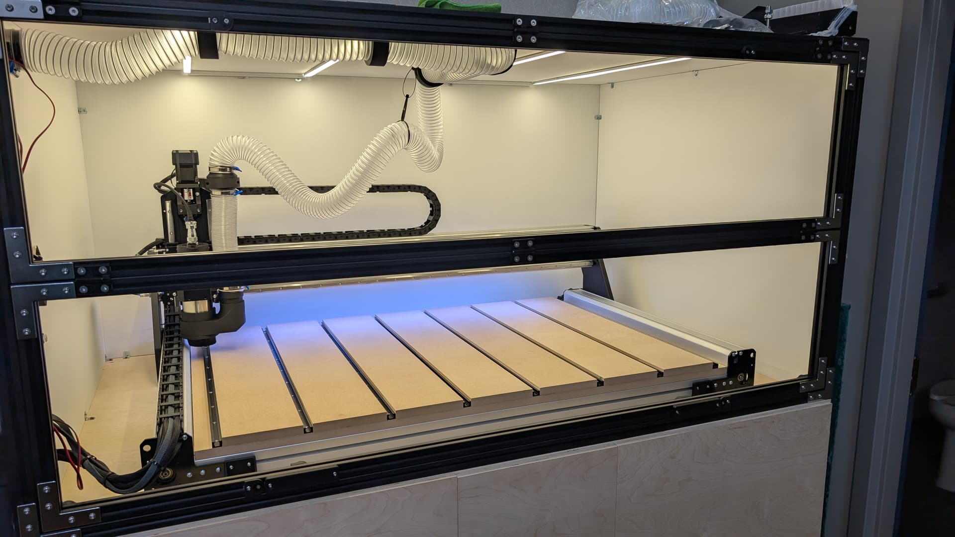
I picked up my Altmil back in June, and it’s been a blast getting everything dialed in. I run an industrial design and fabrication shop out in BC, so I needed something with more production power compared to the MPCNC I was using before. When I ordered the Altmil, I knew I wanted it enclosed—so I designed and built a cabinet while waiting for the machine to ship.

The cabinet was probably the trickiest part to plan without having the machine on hand. I didn’t have access to wire harness lengths, so it was a bit of a gamble. In the end, I ended up mounting the electronics on the side instead of inside the cabinet, and luckily the harnesses were just long enough.

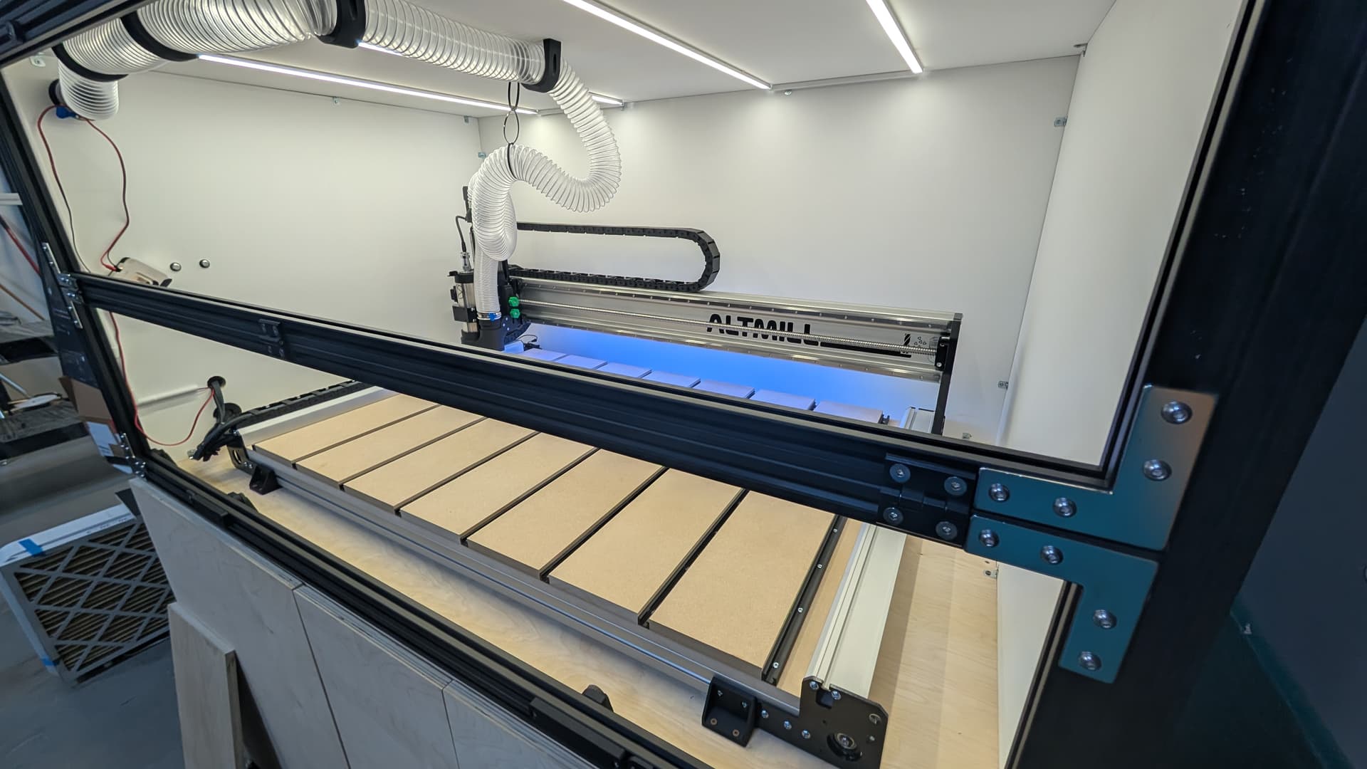
Inside the cabinet, I lined everything with Sonopan to reduce noise. I also installed a vortex separator and shop vac inside the enclosure, which helped kill the sound significantly. There’s an exhaust port to vent the heat—and honestly, the setup works awesome.

Here are a few custom touches I added:

  • Designed and built a custom independent-Z dust boot to clear the vertical flip-up door, running on 2.5ā€ flex hose

  • Flex hose is connected to a retractable cable chain (you’ll see ziptie loops in the photos lol)

  • Custom designed and 3D printed blast gate between the dust boot and manual vacuum hose

  • Mini PC + 15.6ā€ touchscreen mounted on a VESA arm with a custom aluminum plate. The new Gsender came at the right time!

  • Vertical folding 3030 aluminum doors. Polycarbonate windows on a set of 55lb hydraulic pistons.

Since finishing the build, the machine has been running like a champ—2 to 6 hours a day without any issues. Huge props to the Sienci Labs team!

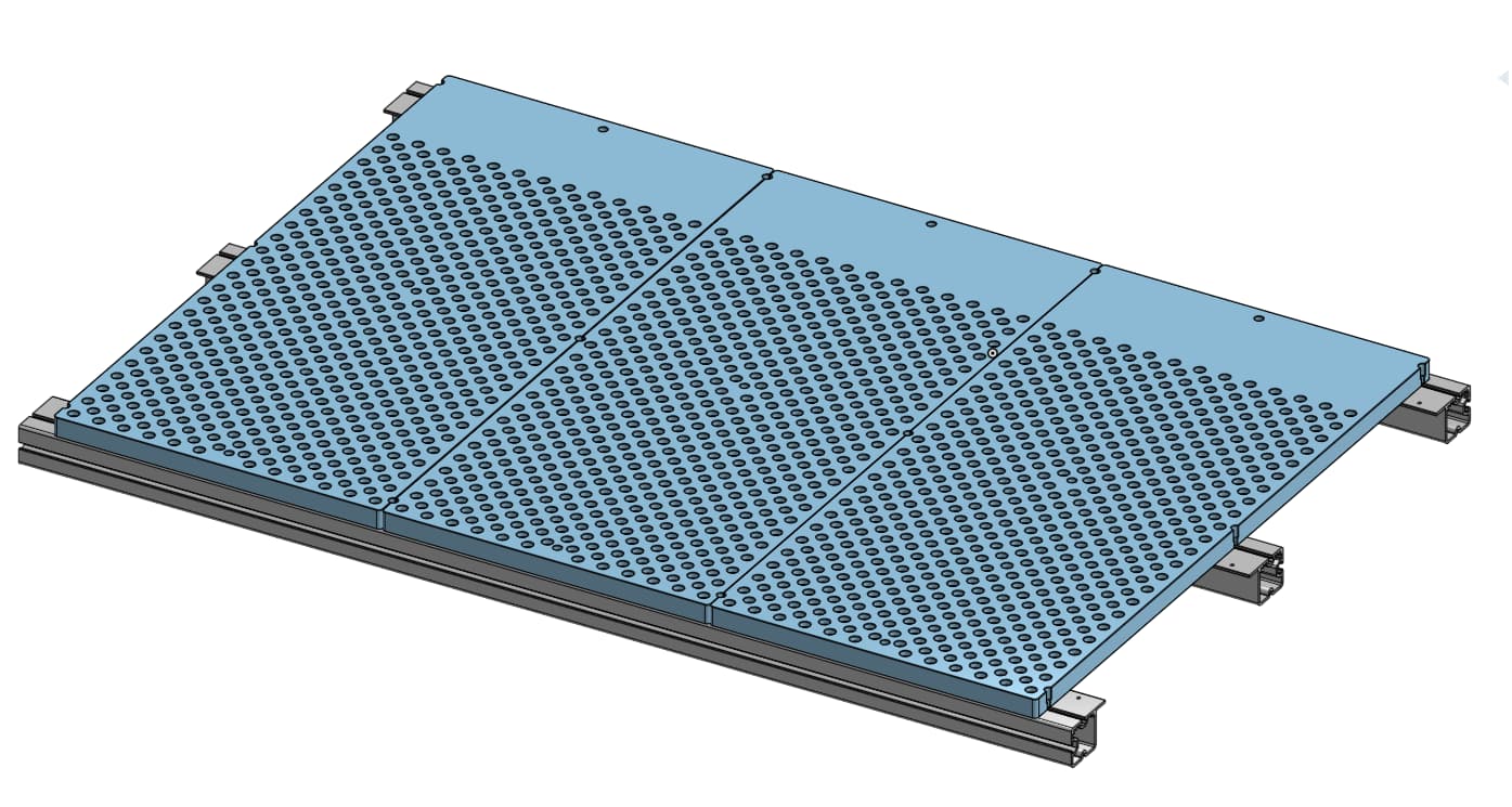
Looking ahead, I’m planning to switch over from MDF to aluminum fixture plates instead of the hybrid slot table. Most of our work involves creating fixtures for both in-house and client products, so repeatability is key. Also super excited to see what the ATC from Sienci Labs brings once it’s released as it’s streamline a bunch of our workflow, but for now, we are making things work.

10 Likes

@Imisky Nice work. Do you have room inside the enclosure to perform maintenance tasks such as cleaning and greasing the rails and ball screws?

Very Nice build! Can you share/reference the file for the 90 degree ā€œhold downsā€ you used to mount to the table top? i too will be mounting to a table. Thanks!

Hello Eugene, welcome to the group!

I’m a fan of enclosures and I enclosed my LongMill right from the start. I also mounted my electronics outside the enclosure. I didn’t get so lucky and had to extend some wires.

Yours is the first enclosed AltMill that I’ve seen and I think it came out awesome. I have thought about how to enclose an AltMill but I didn’t consider mounting it to a table like a LongMill. Brilliant!

Really nice work! Very clean and professional looking build.

1 Like

@Chucky_ott I’m actually in need to perform maintenance. just waiting for the grease and way oil to arrive. From memory, there is about 4 inches of space left and right to access the linear block and ballscrew nut.

The enclosure itself made the footprint quite a bit bigger. Crawling into it is actually ā€œrelativelyā€ Comfortable. I’ve had to crawl in a few times to add the light strips and readjust the end stops

@texmann happy to share them. I’m currently not in front of my computer, will post it when I get in. The thing with the Altmil is the grease nipple for the ballscrew protrudes beyond the base of the frame. You’ll have to put some spacers.

@_Michael

Thanks for the kind words.

In hindsight waiting for the machine to arrive before starting the enclosure would have been a smart move. But that would have delayed the operation of the machine a good week+. I got lucky and really didn’t want to splice the wire unless absolutely needed. It was heavily contemplated.

The style of door to build was also tough. A side ways bifold was originally the plan..but realized that would block the access to the control panel while the machine was in operation. The vertical folding door was a harder plan to execute. But overall a much better design for such a wide machine/enclosure.

1 Like

That’s the way I went. I made the doors go to the left and I mounted the X motor on the right side. The electronics are all on the right side. Now I remember that’s why I needed to extend the wiring. Everything on the LongMill is symmetric with the exception of the drag chain mount holes and bracket. I had to drill a hole and used a bolt with a nut instead of the tapped hole on the X axis and 3D printed a bracket. Everything else just needed to be mounted opposite and the direction swapped in the firmware. I like having my computer on the right side so that was my plan from the get go.

Nice to see confirmation that the altmill can be placed within an enclosure and without the supplied legs. Was there anything needed to be changed/adjusted by not attaching/using the legs?

@_Michael It actually never crossed my mind to switch the motor position but that totally makes sense you could.

@spcnc no modifications needed, but needed to ensure that the surface of that the Altmill would sit on needed to be leveled otherwise there would be twisting on the frame. The only other thing that was needed were some spacers underneath the frame as the open source onshape CAD files showed the zerk fitting above the frame, but the unit had them protruding below the frame by about 3-5mm.

1 Like

Thanks! i actually just got finished assembling the unit on a table. The grease fittings actually did not touch the table but really close. Now to get the spoilboard added. I look forward to the hold down files . Thanks!

1 Like

@texmann here is the machine bracket that i designed. I just checked that there is enough clearance to allow a grease gun fitting to get in there.

machine Bracket.STEP (91.0 KB)

Thank You! Will get it printed shortly and give it a try, much appreciated!

The brackets by itself without spacers will carry the entire weight of the machine so make sure you add the necessary spacers first then use the brackets as hold downs.

yep, i got some 1ā€ x36ā€ piece of aluminum at 1/8ā€ thick, seems to be about right. Really appreciate your help!!

I’ve been busy working on an aluminum fixture plate and thought it was worth sharing. I wanted to utilize the T slots in the cross frame as the mount for the plates so I reached out to the Sienci Labs team for some dimensions as I couldn’t get the onshape files to match the MK2 dimensions no matter what I tweaked.

After talking with them for a bit (Thanks Kelly! if you are reading), I realized the current Altmill source files are for the MK1 (it does say MK1….lol). The MK2 has completely different extrusion profiles—which, honestly, I’m impressed they redesigned. They were super helpful and provided me with an STEP table cross-extrusion beam profile (since the 2x4 Altmill and MK2 Onshape files aren’t cleaned up enough to release yet). With this STEP file, all the dimensions are now correct. For anyone who wants the critical dimensions

MK1. (T slots are both 6mm)

MK2 (top T slot is 6.2mm, side T slot is 8.1mm)

Here’s the direction I’m heading:

3 plates for flexibility, so I can swap in MDF or other fixtures as needed.

Each plate has 563 fixture holes, 9 mounting holes (M6 size)..In total just under 1,700 holes/threads if I was to make all 3 plates

Now I’m stuck on the big question: do I outsource this… or go full DIY?

On another note, did a service on the machine today after putting off the maintenance message for a bit…as we had some heavy machine utilization the last few weeks. Found out that the right side zerk fitting is just at an awkward enough angle that I cant get the grease fitting in. I’ll have to lift the machine up by about 2mm more to really get good access..1mm might work. @texmann make sure you have proper clearance on the right fitting, it’s best to check with the grease gun fitting you plan to use. All other fittings were easily accessible.

Holy cow batman! Them’s a lot of holes!

Interesting that they redesigned the extrusions

Questions:

  1. Have you thought about how you will line up the T nut with the plate so you can get a screw in?

  2. I assume you will still have a spoilboard between the work and the fixture plate. That would cover up all the holes unless you make a custom spoilboard for each job - how are you planning to hit the fixturing holes?

  3. You have a nice CAD model but what happens if your y or X zero sensors move slightly? How are you planning on insuring the fixturing plates, if removed and re-installed, are in the exact same position (since you are using t slots and things can slide along them). I am thinking that you might use the CAD model to locate the fixturing holes but if that isn’t the case then I guess a slight shift will not matter.

I assume the plates are aluminum …. I would outsource this job. It is trivial if you have a CNC and a tapping head but would be a real bitch to do manually.

That will be one costly fixture setup - have you priced aluminum recently. I hope you are planning on using the specialized aluminum (name escapes me at the moment) that is meant for fixturing plates rather than standard off the shelf aluminum. It is guaranteed (sort of) flat and moves less with temperature changes.

How heavy will each plate be if you are planning on switching them out ….

BTW, I am assuming that you are planning on cutting metal bits requiring fair accuracy rather than just wood where normal off the shelf aluminum would probably be ok.

@Imisky Thanks for the info. I was wondering why they hadn’t released the Mk 2 files yet

I’ve been thinking about those same questions.

  1. The 6.2mm T slot from the measurements should be meant for a 20 series-M5. The only way is to shimmy them in and get them to catch the M5 socket heads then get them in place before tightening them down.
  2. The idea is keeping each hole plugged until they are used. Keeps the chips out from the threads and etc. For any wood/plastic jobs, I could simply throw on a thin spoil board. and locate a few of the threaded holes for hold downs. For any aluminum jobs, I’d then be able to quickly index where the vice/fixtures would be and have it be repetitive.
  3. I was originally thinking of using a dial indicator to ensure the plate is located in the correct place relative to the model then adding a machined aluminum reference fence to either the left or the right side for repeatability of plate registration. I’ve been thinking about the the X and Y sensors moving/needing replacement issue…would probably require me to make a fixed "gaugeā€ should I need to replace them so they are installed back to the same distance. Though… we would still locate the stock on any fixture/vice, so it might not be an issue long run. Might have to see it in practice.

The plan if it was a DIY was go with a MIC6 cast aluminum and surface, thread mill all the holes, counterbore them, and profile them all on the Altmill 2x4. I don’t think manually doing this is viable.

Going with Cast aluminum/MIC6 for outsource would still be the goal here..and after sleeping on it last night…It’s probably way more efficient to do that here, all things considered.

Weight might be a problem, with each part at 43lbs on this current version of the design. But having said that, the added weight might help with dampening any vibrations. I might reduce the material thickness a bit here and go with 0.75in stock instead of 1in. Going to have to play around a bit more before I get them fabricated.

You are right in your assumption on the metal parts, getting good accuracy is always the goal here, but the main goal would just be working with Aluminum. But this machine also sees a fair bit of wood/plastic jobs. We’ve considered/joked that we might have to pickup a 2nd Altmill just so we don’t have to change up the machine setup…maybe eventually.

I did not know that you could ā€˜thread mill’ anything with the Altmill. I need to look into that.

Yes, Mic6 is the stuff I was thinking about.

Watched a youtube video on thread milling - very cool ….