would be intersting to know how much you loose in Y travel on the 2x4 when you install the tool rack. Thats the reason i went with 4x4 and my mdf base sheet is 51.75 x 41" currently
Ended up deciding to just go ahead and make the enclosure 48" tall.
There’s absolutely no real need for it to be that tall, but I just can’t afford to have the machine down again for another enclosure upgrade because it needed to be bigger… So bigger it is for me.
That said, I’d still say 41"–43" provides plenty of room for anyone looking to build a shorter enclosure setup. My setup is just a bit more extreme because of the ducting, vacuum configuration, and the possibility of raising the machine again later on.
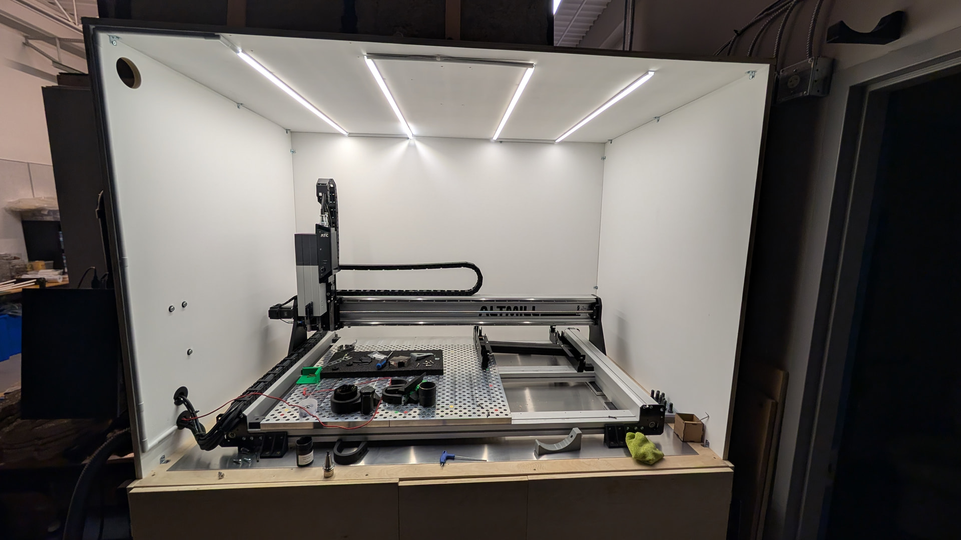
I also got around to putting together the 6-tool rack and… as I suspected, it doesn’t fit my configuration with the fixture plates — both in the X direction and in terms of the space underneath.
I didn’t get around to taking measurements yet, that’s tomorrow’s job.
At this point, it looks like a custom solution is going to be the only way to make everything work properly. The good news is I should still be able to make it removable so I can retain the full functionality of gsender and the full cutting area when needed.
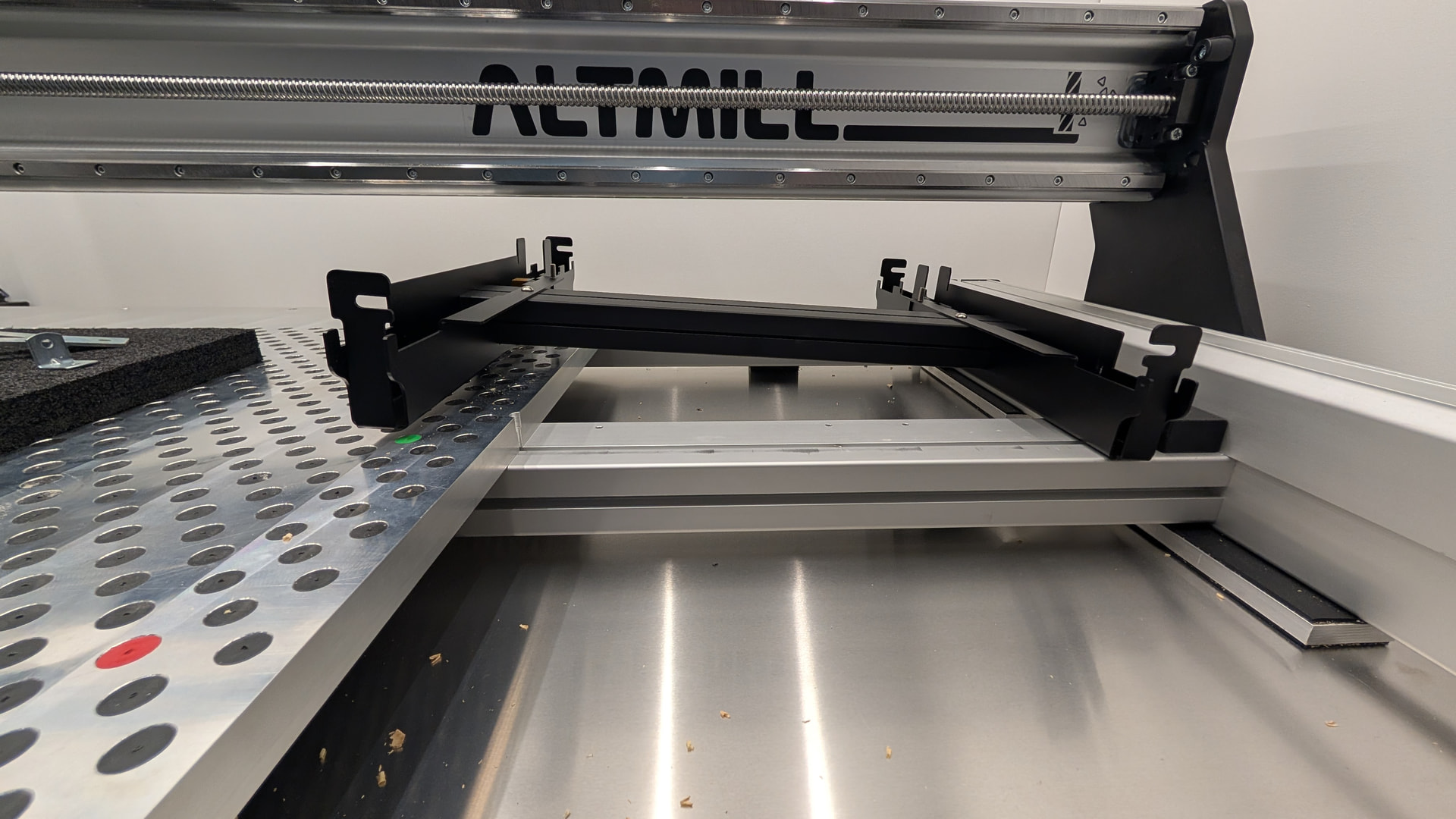
Most likely will have to also look at a retractable/auto detactable dustshoe design…
@Altmillal1114 I think the specified Y axis cutting goes to 20.3” down from 25". It’s likely that my custom solution will also end up at the exact same remainder cutting area with the tool rack.
thats what they told me. Are you planning to do retracting rack or same as OEM?
just noticed in the picture, isn’t it suppose to be along Y axis on the back 2 crossmembers? this looks like its on the right side not the back. is that the spot you want to mount it in?
Very high chance here that I’ll stick with OEM style rack. I’m looking at the ports that’s available for mist coolant + retractable dust shoe. If there are extra ports to use, I might make a cover but that’ll have to be for later.
As for the picture, the Altmil 2x4 only has 3 crossmemebers, what you are looking at is the rack on the back 2 members but tucked to the right. That’d be the spot where I’d want it to go. I believe it’s also the spot that Sienci recommends for the single rack
ah now i see it. Yep. would be interesting to see what you come up with for mist and dust shoe
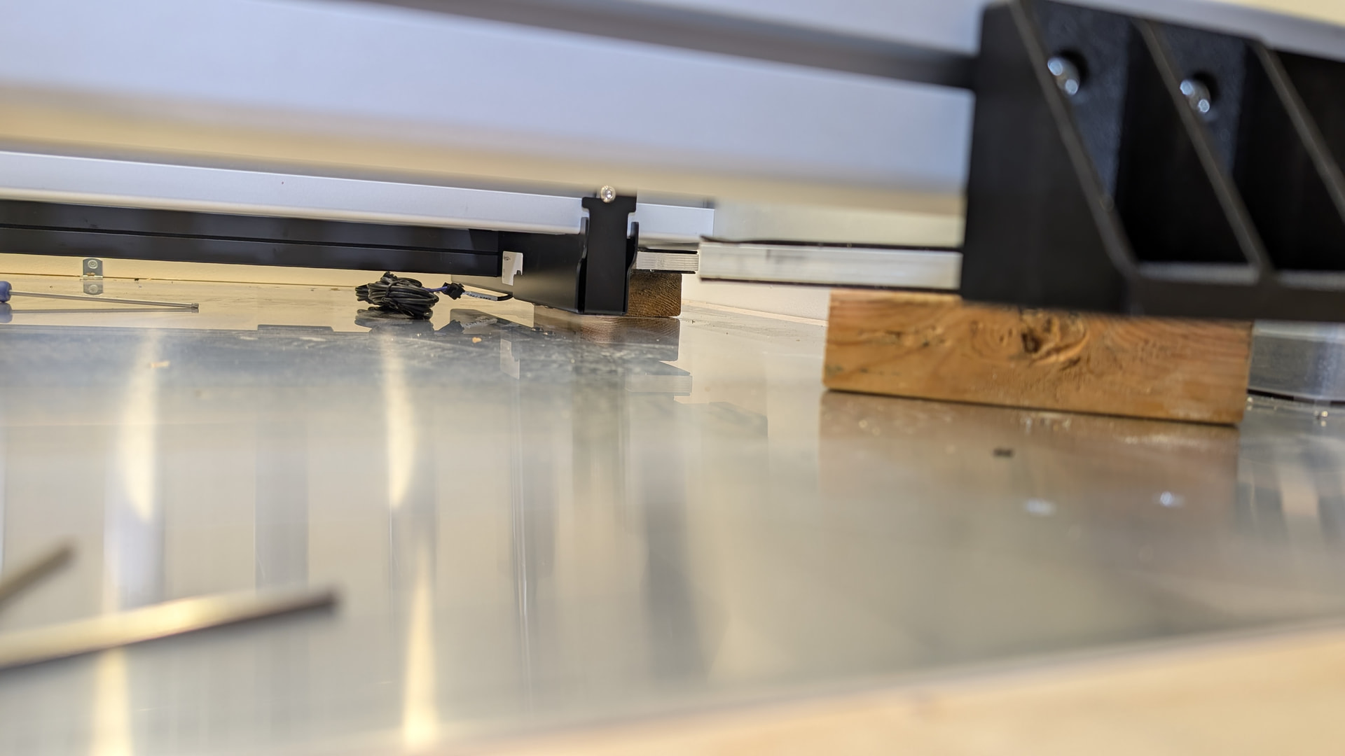
For anyone planning to get the ATC and use the Sienci 6-tool holder rack:
You’ll need to lift the machine by approximately 2 1/8".
- 1/2" aluminum block
- 2x4 (which is actualyl 1.5x3.5)
- 1/16 neoprene rubber x2
Otherwise, the tool rack sensor plug won’t clear properly underneath the machine.
Also pulled all the critical dimensions for the ATC setup needed to design the custom rack and dust shoe system - including the ATC spindle itself and the OEM tool holder locations that Sienci Labs uses.
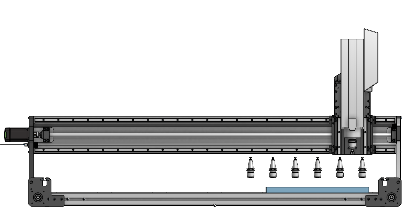
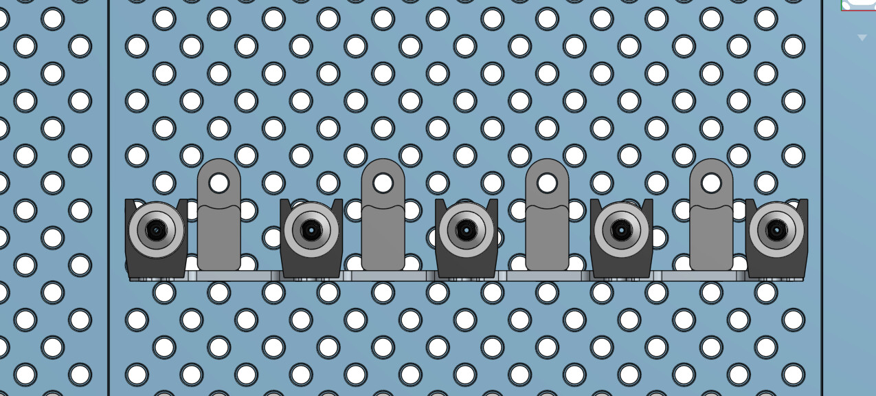
Seeing it laid out like this actually opens up the possibility of designing a custom tool rack directly on top of the fixture plate, since none of the tools we use have particularly long stick-outs.
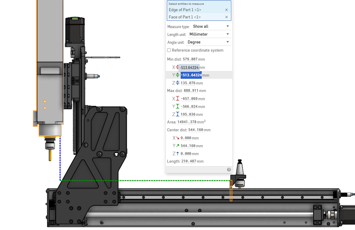
In the OEM location, the distance between the bottom of the tool holder and the fixture plate sits at 38.69 mm. That can also be increased by another 5 mm, bringing total clearance to 43.69 mm (1.72").
The spacing between the tool holders also sits at 90 mm center-to-center, which appears to have been designed around the dust shoe that comes with the ATC.
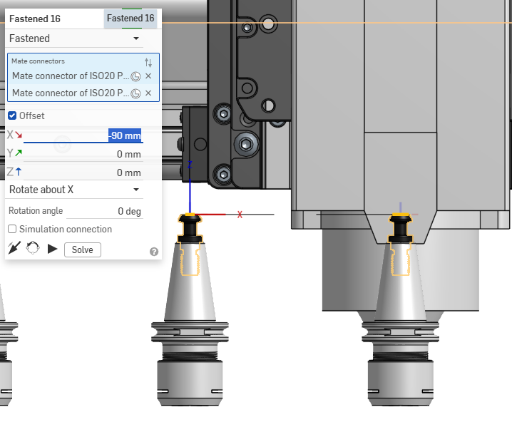
A custom solution might be able to bring the spacing down to around 75 mm.
If that works, I could potentially fit all 6 tools onto a single fixture plate. Otherwise, I may turn this into a 10-tool system instead — starting with 5 tools on one plate, then adding another 5-tool plate later if needed.
We’ll see where the measurements and clearances end up landing.
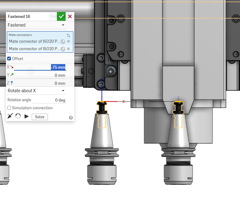
Oh man…went down a giant rabbit hole. Spent a bunch of time modeling this. I think I’m going to go with a 5 toolholder rack with standard Sienci spacing which is 90mm a part. It gives me the ability to make 2 of them and add a 2nd one when I need to. I did move the holder up by 5mm, but this is just optimizing at this point.
I’ve reached out to Sienci labs to see if I can get the actual tool rack clips STEP they’ve designed. For now I’ve just captured something to give me the critical dimensions for making the face plate.
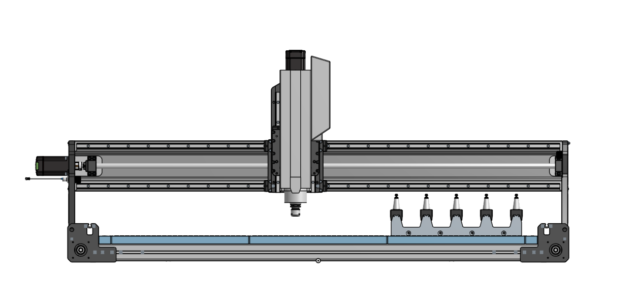
I havent finalized the “front plate” yet, but I might make it more of a shield, so the 4 notch down isn’t as low.
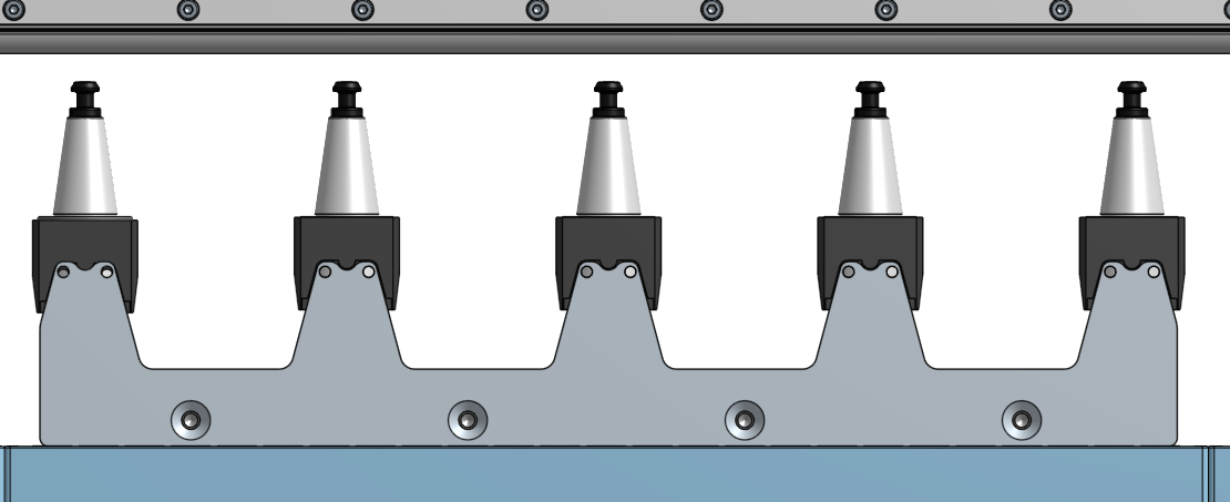
Below is how I plan to build the “hold downs” and fixture it onto the build plate. I might keep the “rack sensor” by putting it behind one of the hold downs by using 2 dowel pins for registration and quick removal when I need to remove the rack.
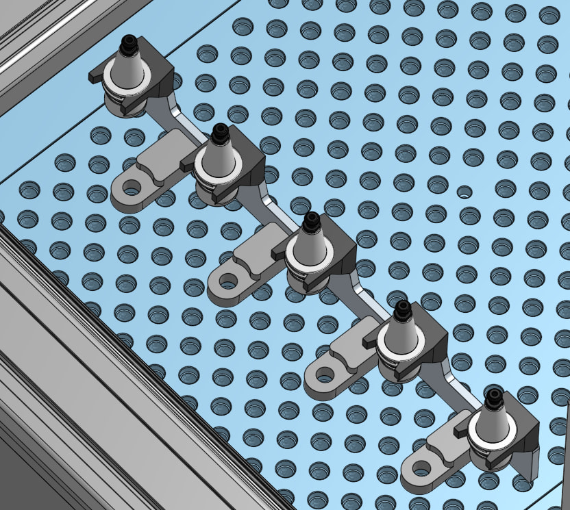
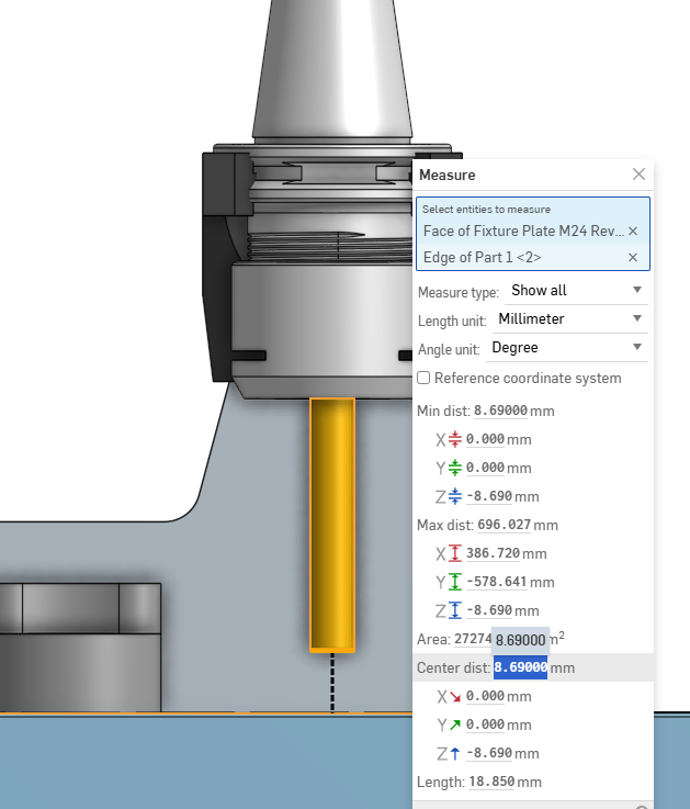
simulating a 35mm stickout on a 6mm endmill, still have 8.69mm of space.
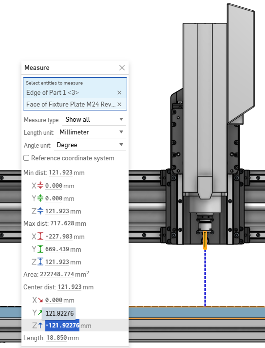
With the spindle all the way up, I still get 121.92mm (5.19") of Z area cutting with 35mm stickout on the tool. minus any fixturing.
With the carriage all the way up front, The Y axis cuttable area on the stock OEM tool rack position 513.64mm (20.22") which is right around where Sienci Labs states their rack would reduce it to. with the fixture plate setup I could move the rack back by a fixture hole, which would give 31.75mm (1.25") extra space. in the Y. so I think if I’m really pushing for maximum cuttable space, it’ll be somewhere around 21.5"
Onto the custom dustshoe… I think I am going to go with Francis Creations AutoDust boot controller. As the documentation of the ATC from Sienci uses SWT1, SWT2, PWR1 aux ports, I’m left with Coolant + PWR2 to control mist coolant and the retraction of the dust shoe. I’m planning to use PWR2 on a 24V solenoid for the mist coolant. Alternatively.. I could get an IoT relay for the coolant port and a 110V solenoid to trigger the mist coolant and have the PWR2 port for the auto dust boot.
@siganberg, is it possible to use coolant port 5V , or use PWR2 for your Autodust boot controller? want to collaborate on this?
wow nice progress. I’m jelous and impressed with your fusion skills  Ping Francis over on his discord, you might get fast response as he is pretty active there
Thanks Alex, it helps to be an industrial designer, and run businesses that use CAD on a day to day. It takes a while but you’ll get there. I do most of my work in Solidworks, but Onshape is close enough so I use it for the odd thing here and there for personal projects. Fusion for CAM only, something about fusions CAD has me confused when it comes to their assembly/mating system.
good point about pinging Francis over on his discord, I’ll do that.
1 Like
Control signal for AutoDustBoot is 3.3v to 5v. Power supply is 12-24v.
I sent multiple emails to Sienci asking if they can provide or loan their ATC so I can both build an AutoDustBoot version for it and also develop a plugin for ncSender so users of Sienci ATC can use it in ncSender. I have been approached by users multiple times to support it, but purchasing one mostly for the community is not financially practical for me right now. Most of my products are really niche market and recouping investment is not really realistic as I still do this as a hobby. 
1 Like
Thanks for the control information. I’ll pickup a Autodustboot controller from you and design a version of a dust boot system of my own.
It makes sense too that a $4500 system is hard to justify development.
I’m happy to help out anyway should you want someone to collaborate with on your Sienci ATC product. I’m not here to make money off my creations on the Sienci platform, infact I’ve got nothing to sell lol. Just showcasing what’s possible should anyone feel they want to go down this route.
Had a friend help with getting the brackets and plate made while I was setting up the machine.
For those with a keen eye, don’t judge my cap screws in counter sunk holes, had to work with what I had at the time. Flat heads are on the way. 
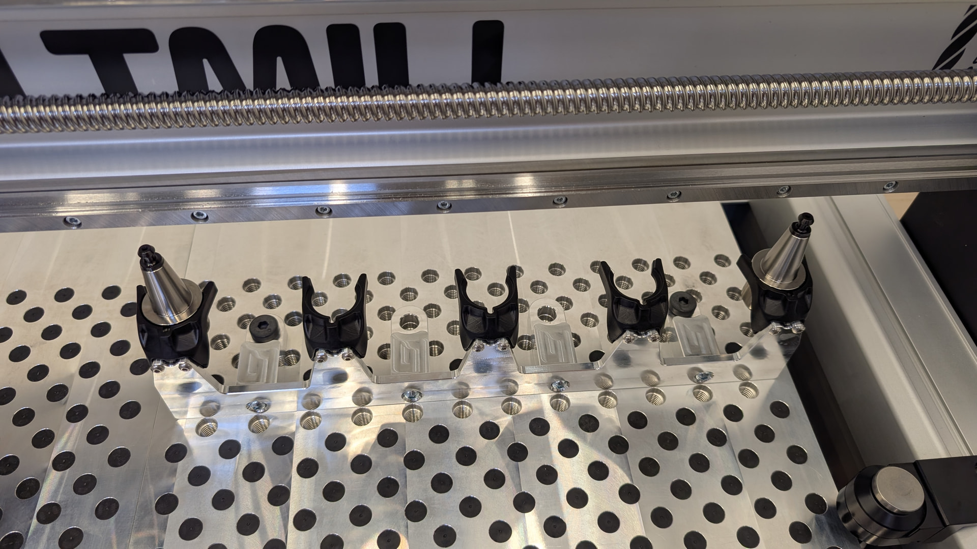
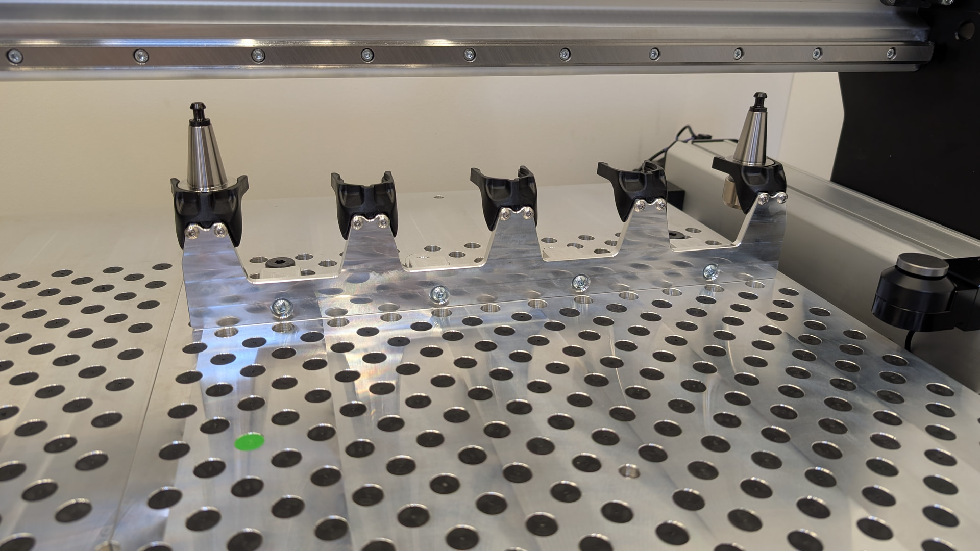
The team over at Sienci has also been great on helping me get this unconventional setup done as well!
For anyone looking to setup their own custom tool rack. Here is the process to follow. (This process might change with software updates)
- Start setup wizard
- For Rack Size Pick 6/12 tool rack to setup
- apply the controller settings
- re home the machine
Up to this point, its all the standard setup
- for rack position pick manual
- Move the spindle directly over the taper (the menu will ask you to remove the pull studd, I did not) I centered and lowered the spindle so the tapers lined up. and left about 2mm gap.
below is the instructions by Sienci labs for this step
In the setup wizard, use "manual" to define the position of the left-most pull stud (i.e. Have the spindle taper directly on top and enveloping the first pull stud, then set that as the location of your rack. You may have to try it a few times if you don't get the height right the first time around since the spindle drawbar will push the tool holder out by 2mm from the locked position and if you set the pickup location too low, the forks may not be able to soak it up.
- After setup is complete, turn off the controller, remove the SD card and find the P100.macro in the root of the SD card.
- Open P100.macro and edit the field <_tc_slots> so that instead of 6 / 12 it equals to 5.
- Reinstall the SD card, restart the controller and re-home (ideally from outside of the rack area to prevent crashes).
- Try a tool change.
**Inside the P100.maco you’ll also find other values to adjust such as the tool spacing, you’ll find the default of 90 in there.
One of the other thing I had to adjust is the tool change keep out area when the rack is installed and the sensor is active. I have my TLS at a location that was in that keepout area but I didn’t find any reason for it in my setup for now (this might change after the dust boot is designed). So I had to adjust the Y axis keepout value so that the probing sequence would work otherwise I kept getting an error 2 soft limits hit.