I’ve been going back and forth with @Altmillal1114 on tramming the Altmill and I thought it’d be good to just document this for everyone.
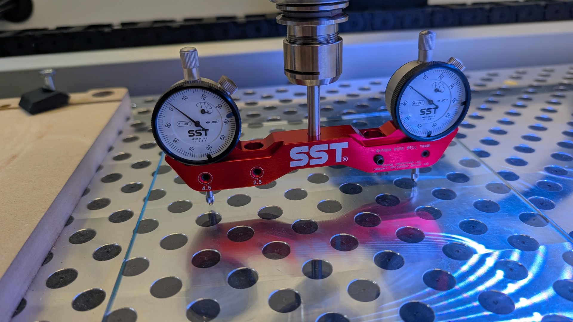
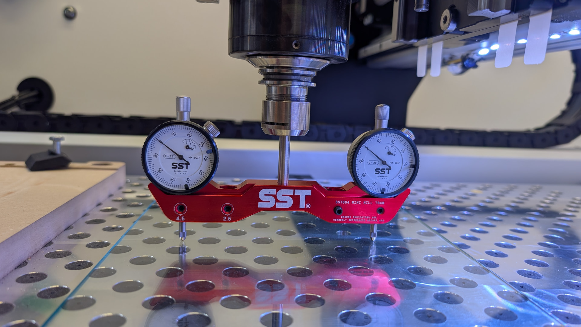
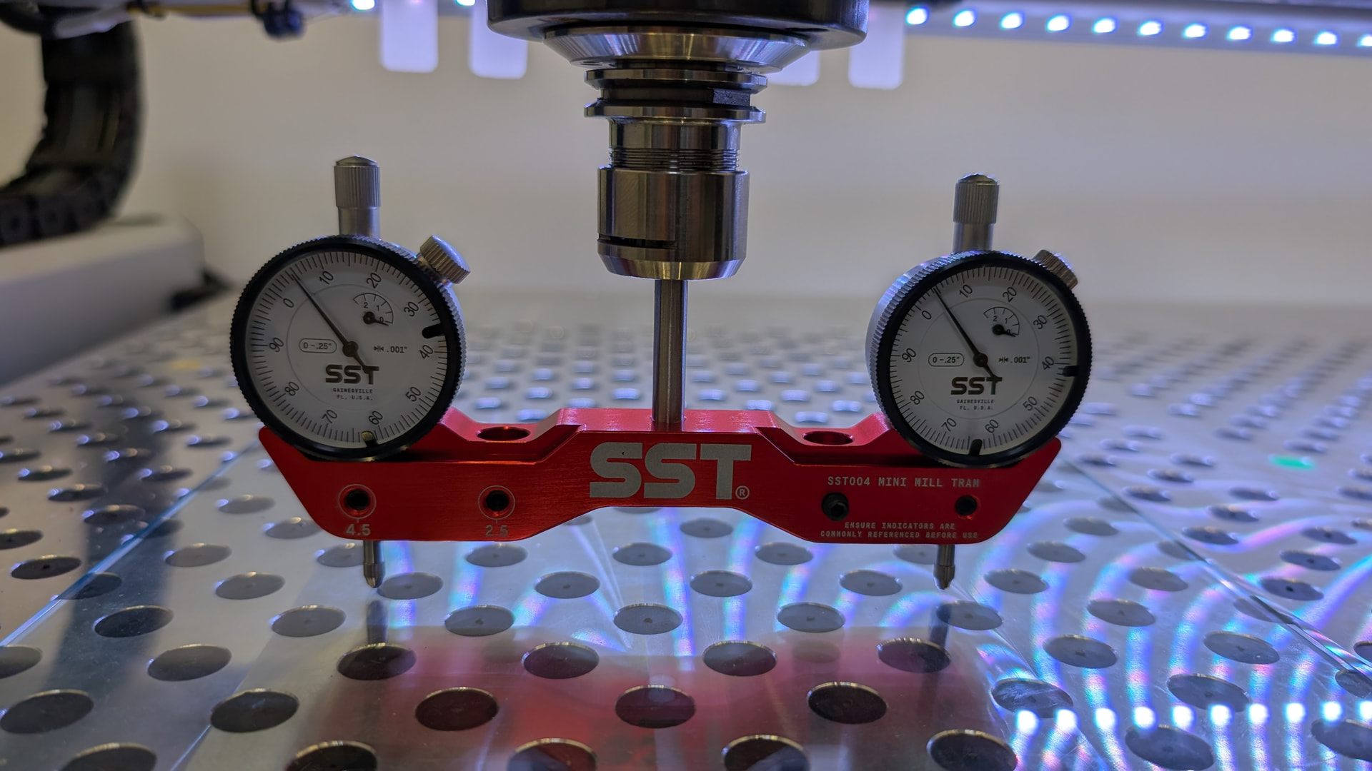
If you have a tram gauge, this process is pretty fast and straight forward, otherwise a single dial indicator in the spindle works very well too. I use the SST tool, but doesnt have to be from them, nor am i sponsored or affiliated with them.
You’ll also need a reference plane, My build surface was already quite leveled. But you can shim a piece of float glass with paper, or use something more precise if you have access to it.
So the Sienci resources page is already pretty good, but it has instructions for the 1.5/2.2kw spindle. The ATC spindle isn’t much different, in fact the process is pretty much the same.
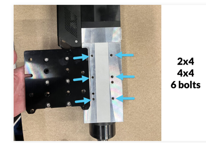
The only thing I would add is, make sure that when installing the ATC mounting plate, to properly seat the plate against 1 edge of the 6 bolts used. In the picture below, either push the plate fully up or down towards the top of bottom of the spindle. Sienci doesn’t call out to do this in the assembly process, but because there is play in the holes, you are trying to get the plate mounting holes as parallel to horizontal plane as you can to the spindle.
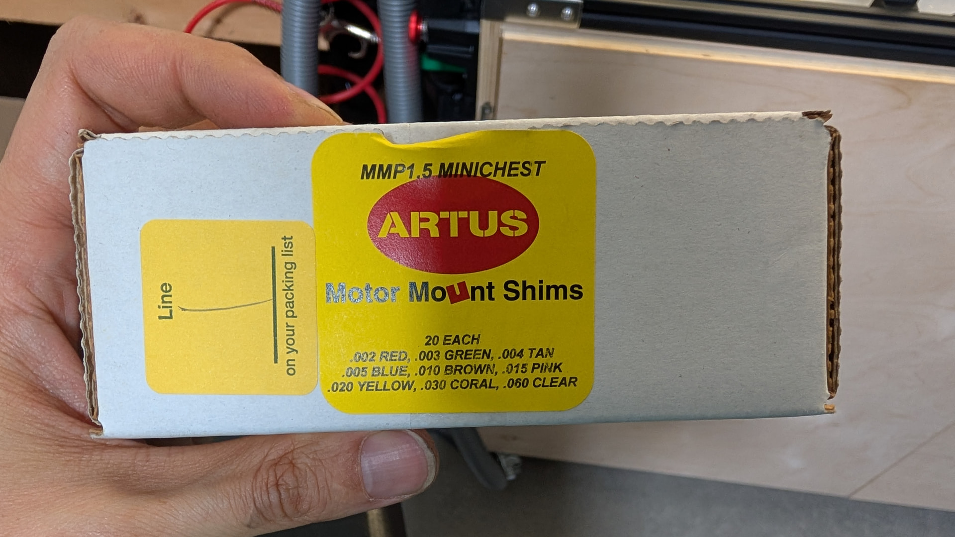
Here are the mounting shims I used to dial in the nod. The colors indicate the thickness.
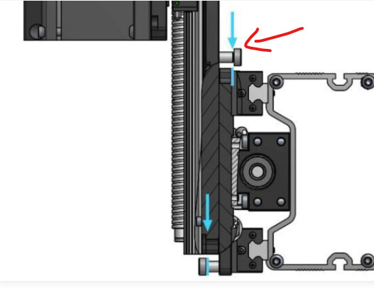
Sienci’s instruction says to loosen the one on the back of the Z carriage plate, I didn’t need to do that as the mating surface in blue wasnt even engaged with the bolt fully bottomed out. (Red arrow). It simply acted as a “hanger” for installation.
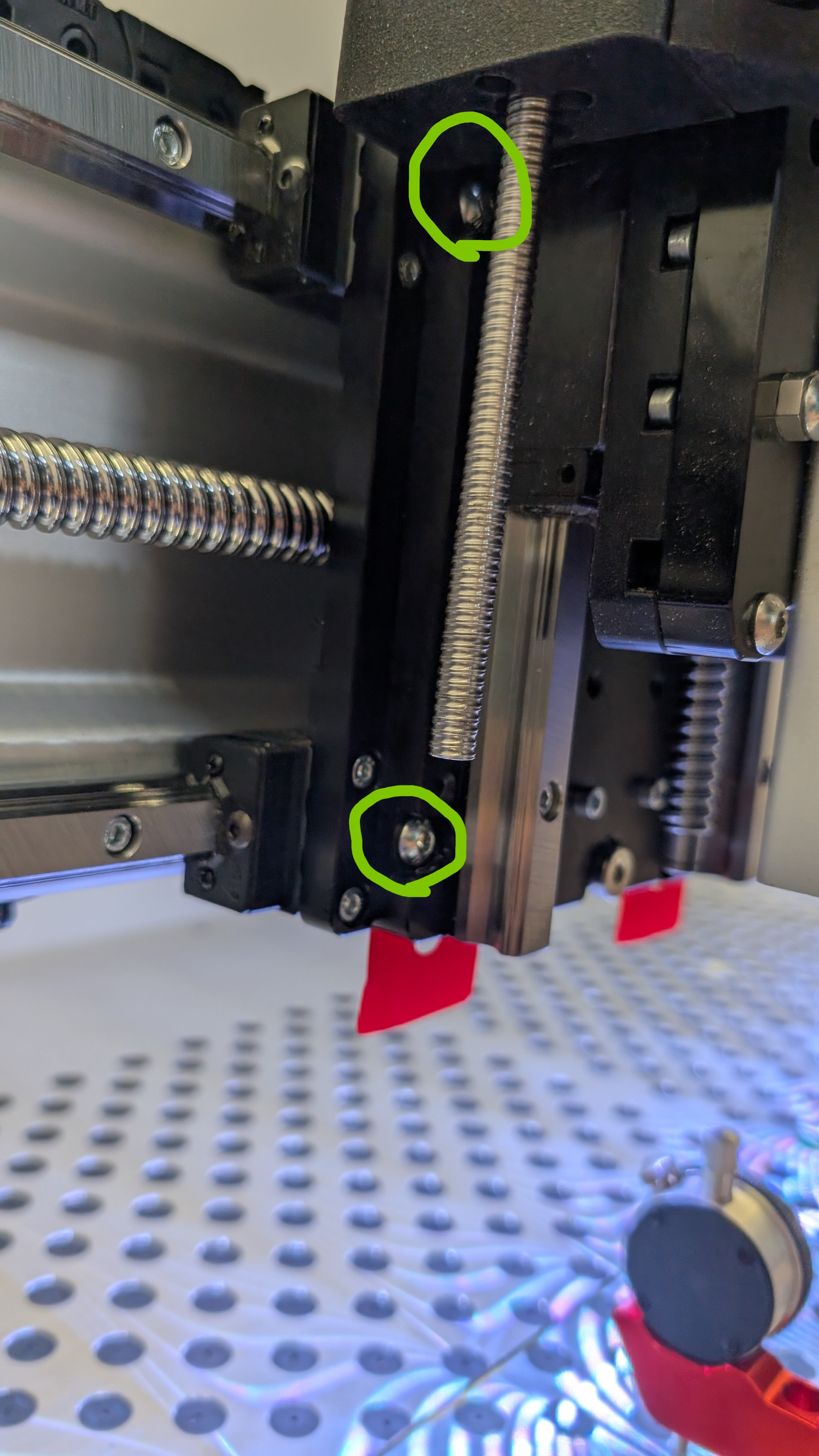
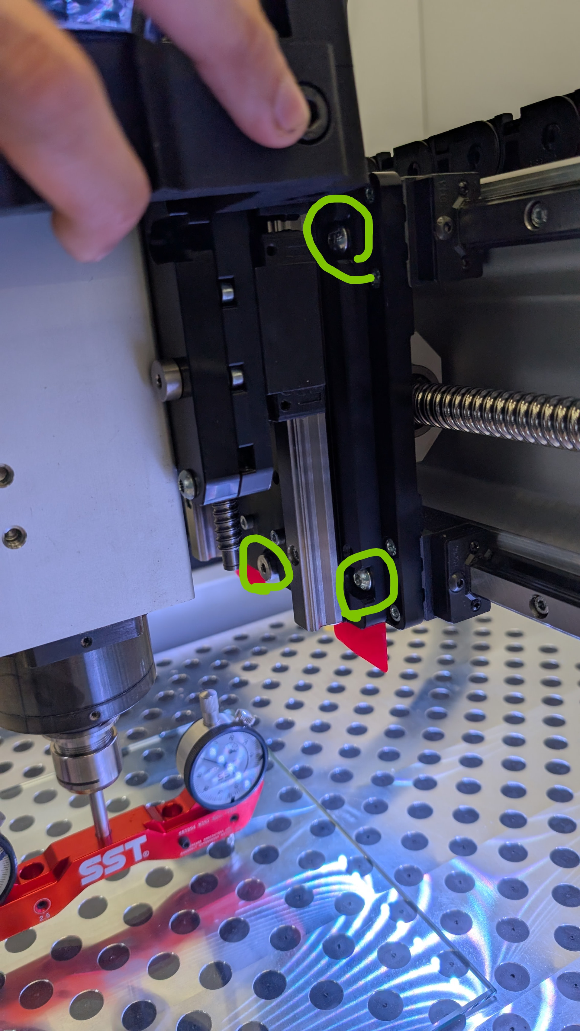
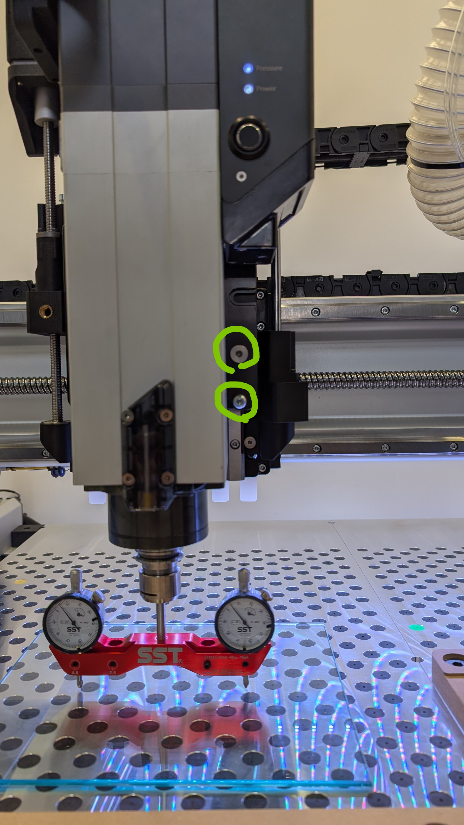
With the ATC spindle mounted. Loosen the 5 screws circled (one of them is the shoulder bolt under the ball screw). Add shims near either the top 2 screws or bottom 2 screws, then tighten and take a reading to confirm your adjustment. if your readings got worse, you’ve got the shims on the wrong side, for me I needed to add shims to the bottom 2 screws.
I originally had red shims in (0.002") as you can see in the photo, and my nod was still off by 0.002"
Switched the tan shims to (0.004") and the nod is dialed in.
For the Tilt:
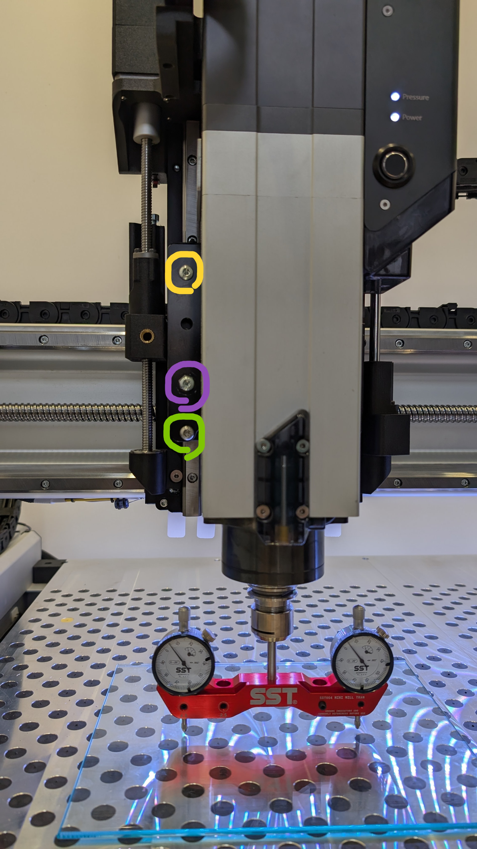
Install the spindle with the provided shoulder bolts, don’t use the eccentric bushing yet and take a reading with your dial indicator. If there is tilt:
- Remove the shoulder bolt circled in purple. and replace with eccentric bushing + m6 bolt
- loosen the screws circled in green, then snug them up but not tight (bottomed out and a pinch more)
- then turn the eccentric bushing until you get the same reading on your gauges.
- tighten all the green circled screws first, then the one with the eccentric bushing.
- OPTIONAL add the screw circled in yellow