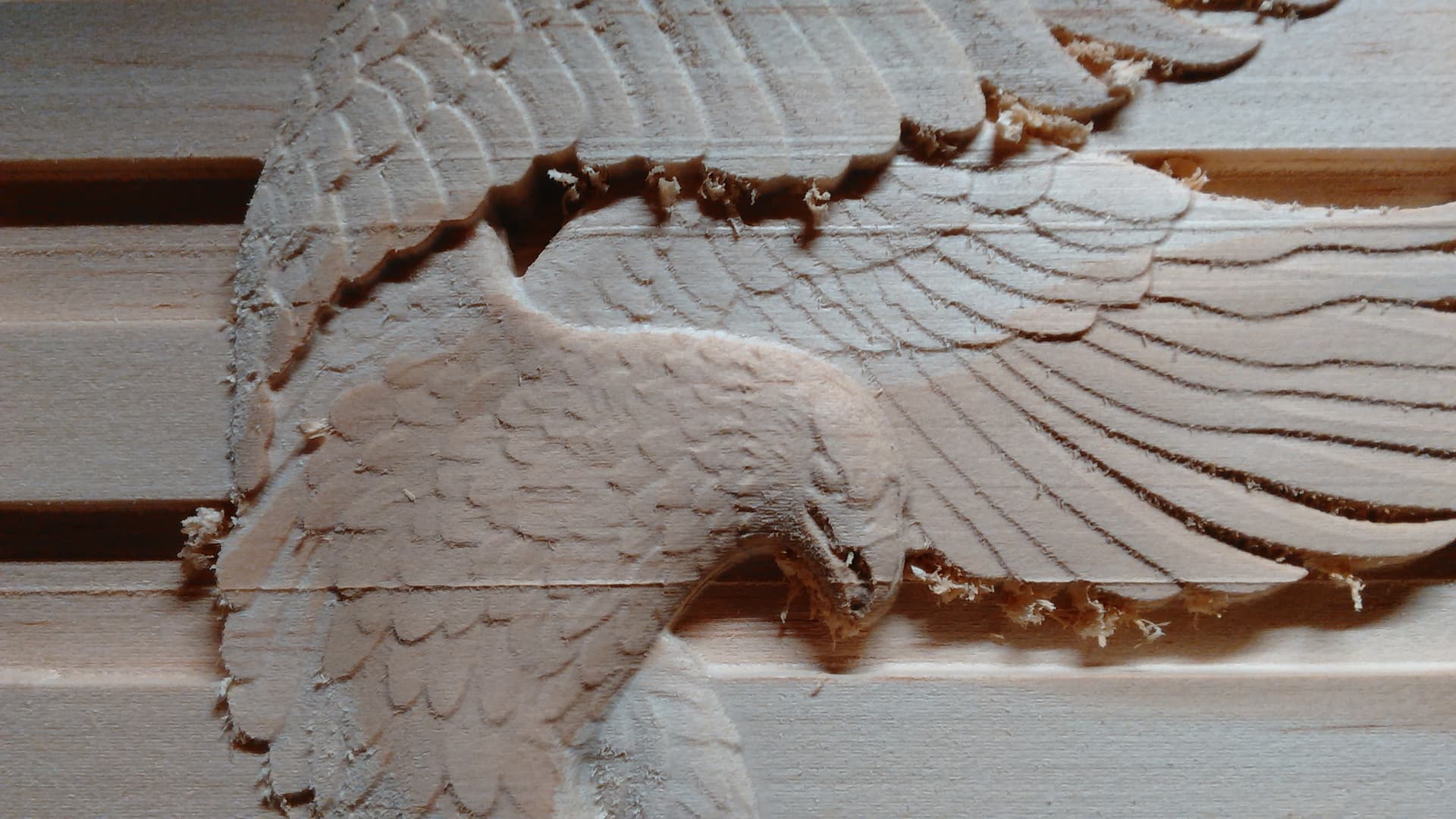
Here are two projects I’ve done where there is a raised line going across the X-axis. The pic shows it as fading in and out but that is because I have been sanding them before I decided to post and ask. They go all the way across and do not vary in height except line to line.
The other issue is for some reason it does not cut a straight line as it passes the start nodes. As I was posting the pics I noticed where it dips in is more on the top of the material than the bottom. Could that be flex in the bit from not fully loading it in the collet?
Lonnie, my first thought it is mechanical then you advised the depth varies from top to bottom of material, still mechanical as far as alignment.
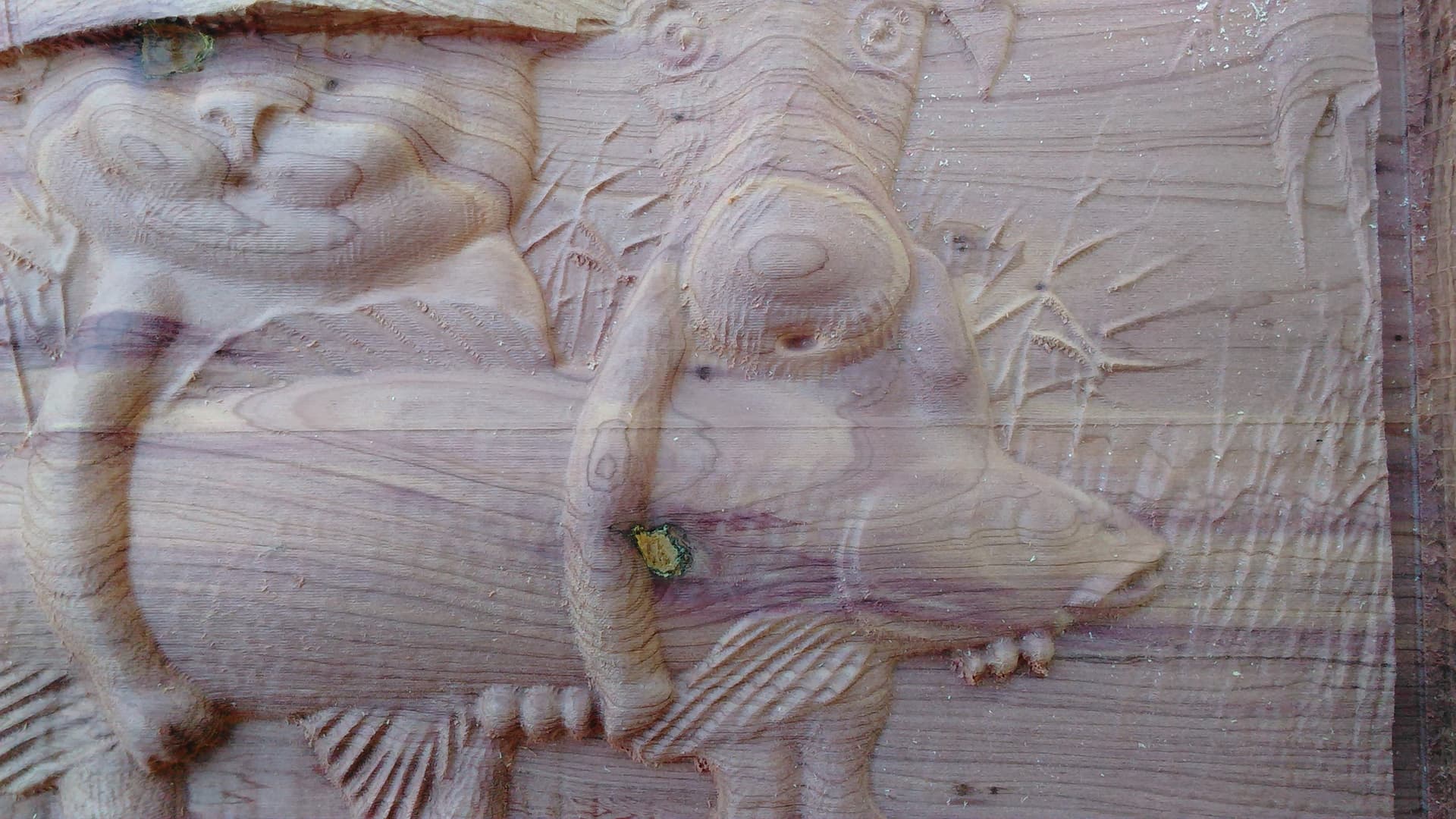
I would go through the mechanical set ups again, check the wheels, check the anti-backlash nuts., and for sure resurface the waste board. The pattern also continues below the obvious horizontal lines, what feed rate were using? I don’t see what’s up on the last pic.
Difference from top to bottom means something is not aligned, resurface the waste board.
@Swinly In addition to what @Bill said, I would check to make sure that the material is dead flat. I don’t know where you are, Lonnie, but in my basement shop, between the time that I joint and plane rough sawn and when I actually use it, it can cup or twist quite a bit.
feed rate on the reliefs was 157in/min. I don’t recall the RPM, I think 2+ on the Makita with a 1/16in tapered ball nose. The profile cut on the last pic was a 1/8in down cut with shallow passes. Feed and RPM on that one escape me at the moment.
I’ve never broken down a CNC, is there an order in which I should do it? Did Sienci make a video on this not too long ago?
Edit: My v wheels are on pretty tight could that be an issue causing this?
I agree with @Bill to check all your gantries for any slop. There should be no movement if you try to move the gantry (X and Ys) back and forth. If there is, tighten up the anti-backlash nut a bit. For the Z gantry there should be no slop if you try to move it up and down. Also see if you can rock the bottom forward and back. If you can you need to tighten up the V wheels on the Z gantry.
I’m not sure if one of these are your problem, but they are quick checks.
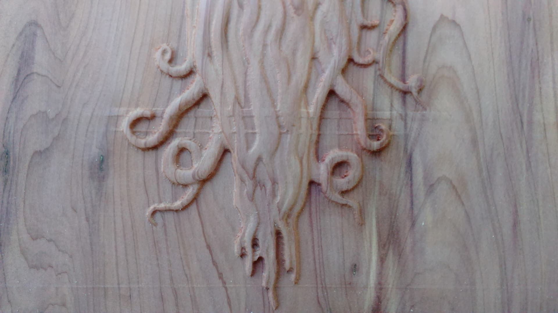
From the fish picture it appears that Z shifted up when the high lines were cut, but appears to correct and go back to the correct height. I’m not sure how this happens mechanically. It could be in your design file. It would be interesting to rerun one of the jobs to see if the lines recreate and, if they do, if it’s in the same place.
I don’t think that these lines have anything to do with your waste board surface or a non level (i.e. varied thickness) work piece. I don’t think those kind of issues would cause such distinct lines.
Regarding the last picture, if you had slop in your X gantry it might show up like this. As far how far to insert your bit, take your collet apart and see how far you have to insert the bit before the inserted end of hits air. There is no point in inserting the bit past the clamping surface of the collett.
Finally, in V carve there is a function called “ramp” which you causes the bit to plunge more slowly over a specified distance to help reduce the deflection cause by a quick plunge. However, your “deflection” seems much more than normal. Hope this helps.
I’m just trying to understand how out of tune wheels and/or anti-backlash nuts could cause this. I’m not trying to be argumentative. I’m just trying learn.
On my PC, the first pic shows three distinct ridges, the second shows one and I don’t see anything in the third pic. In the first and second pics, before and after the ridges, everything seems fine, yes? In the first pic, between the ridges, the model looks good, yes?
I’m likely missing something, but if the wheels or the anti-backlash nuts were out of tune, it seems unlikely to me that almost all of the model would cut properly. I guess what would be nice to know is: are the ridges in the same place “geographically” on the Mill from file to file. Or, do they appear in random locations? If they are in the same location wrt to the Y direction, could there be something on the Y gantries that is raising the router as the wheels pass it?
All this said, I think that my original thoughts on material issues are wrong. (I seem to be on a roll lately.)
For the first two pics I tried to match the different projects up to see if they were in same location but I really couldn’t tell.
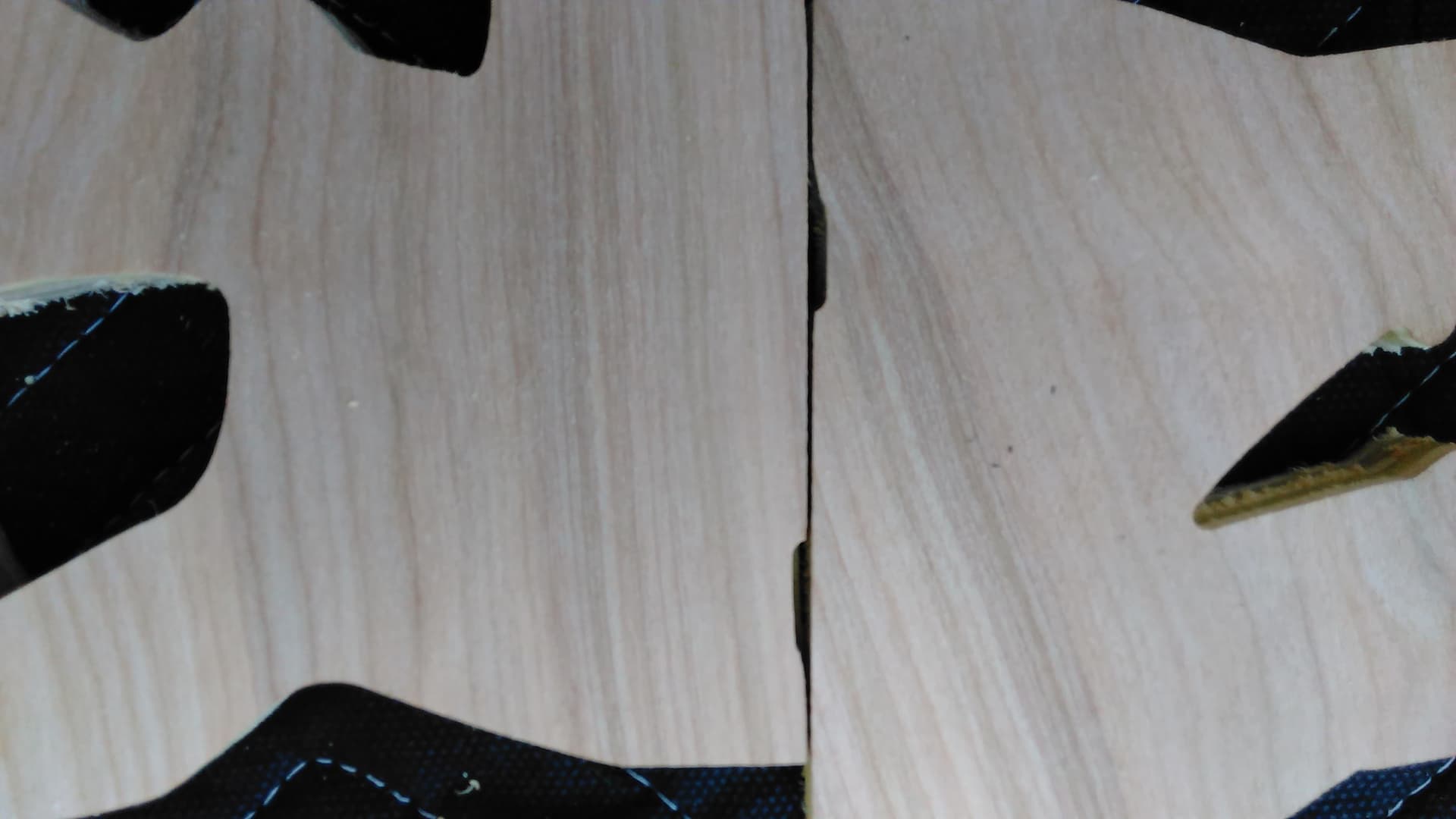
The issue with the third pic is different than the first two. The two pieces are supposed to be straight edges where I butted them together but they dip inward for about half an inch. When I looked at my designs in carveco I noticed they always dip inward right at the start nodes
Grant,
I agree with you on the lines. But those gantry checks are quick and a sloppy X gantry might contribute the last problem (third picture) Lonnie was asking about.
Assuming the pictures with lines were raster cut top to bottom, or vice versa, I don’t know how you go from correct cut height to wrong cut height and then back to correct height with a mechanical issue.
@Swinly@paullarson@Bill Lonnie: Speaking only to the third pic, if you are saying that, even in the preview in Carveco, you see that the edges are not straight, that is simply weird. If you can export a .dxf file and post it, we can all look at it to see if there is anything in the file.
If I am misunderstanding and it’s just the cuts that are off, I’m with Paul on the ramping technique. I use it pretty much all the time, but especially with thin bits. If your software accommodates ramps, they may well solve your problem. They really help with bit deflection issues.
Yeah, it’s just off on the cuts. I’ll start looking at the ramping feature. It mainly stands out when doing a profie cut.
I watched the video on Vwheel tuning yesterday before fiddling with it and I am pretty sure my wheels were on too tight so loosened them a bit. The backlash things, well, I have no clue what I’m doing with them. Can those be in too much? I did find through my checking that I can lift the lead screw on the Z-axis ever so slightly.
Just tighten the anti-backlash nuts until you take the associated slop out. You can tighten too much which would make it hard for the stepper to turn the leadscrew.
@paullarson@Swinly Kelly suggests that the ridges could be caused by the Z gantry being bottomed out during the cut. How is your router mounted, Lonnie? Is it high or low in the clamp. If it is high, you may want to lower it and try the project again.
That said, I must admit that I am completely baffled by how, if the Z gantry is bottoming, the cut can continue after the ridges and be fine. However, I bow to the greater experience of Chris and Kelly in situations such as yours.
@gwilki@Swinly
I had the same thought, but it could only be the case if the Z gantry bottomed out (or the bit shifted up in the collet) and those raised lines were the only cuts made afterwards, which seems unlikely. Once the Z axis is off it’s not going going to correct without manual intervention.
Okay, I have another carve going now. Just started the finishing tool path so it will be a while before we know if there are any ridges going across.
I do have the router all the way in the holder. I did fix the play on the Z lead screw, tightened/loosened the v-wheels, and tightened the anti-backlash bolts.
As I was adjusting and cleaning I saw that the M5(?) bolt on the anti-backlash hits the locking nut on the top of the Z lead screw. That might be what created the little bit of play I had there. Is it normal for that M5(?) bolt to top out and hit or should it be tightened far enough into the anti-backlash things, so if it does top out those two will not be hitting each other?
If you are unsure what I’m referring to I’ll post a picture in a few.
 If you can export a .dxf file and post it, we can all look at it to see if there is anything in the file.