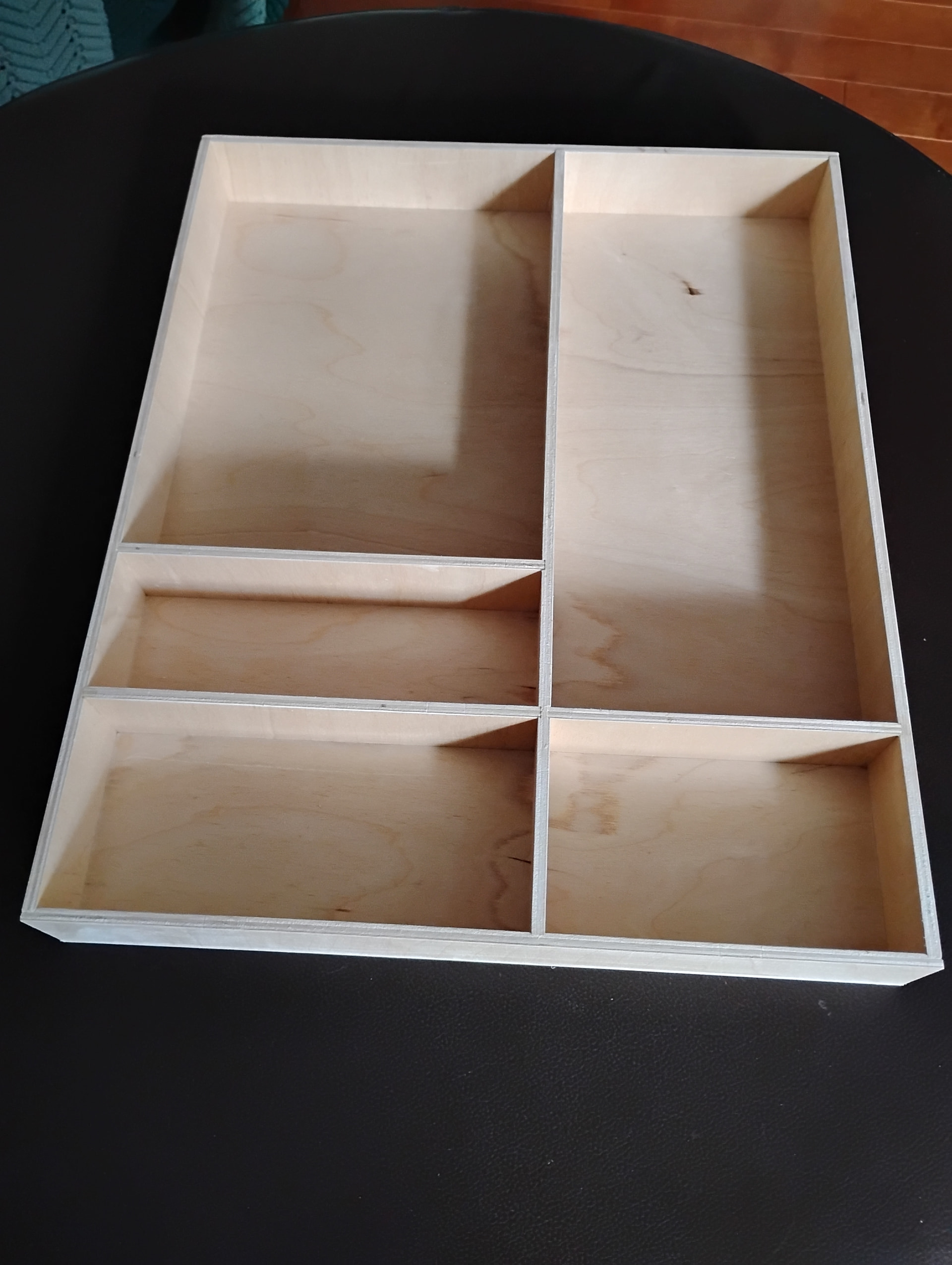
Nothing impressive about this project. It’s just a simple cutlery tray for my daughter. This is the second one I did for her. The difference with this second one is the use of a 3D Probe to do a surface map of the plywood before carving.
Plywood, and especially thin plywood like the 6mm Baltic Birch plywood used in this project, is hard to keep flat. I don’t have a vacuum table and while I could have used the tape/CA glue hold-down method, I wanted to experiment with height mapping.
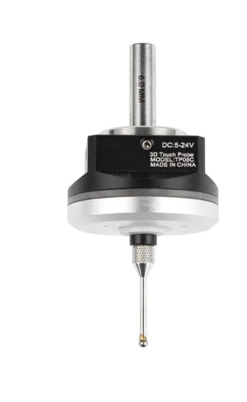
So I bought myself a 3D Probe like this. This is the NO (normally open) model and plugs into the TLS port on the SLB-EXT
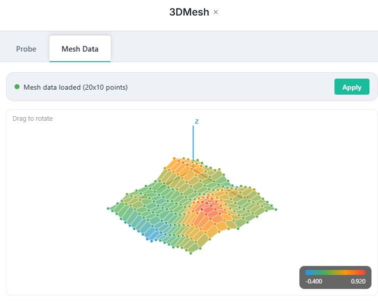
Since gSender doesn’t have the height-mapping feature yet, I used ncSender (hey @KGN, is this imminent in gSender?) . You essentially import the g-code for your project and then run the height-mapping plug-in (ncSender calls it 3D Mesh). This probes the surface of the plywood using the grid spacing you want, and then ncSender compensates the z moves accordingly.
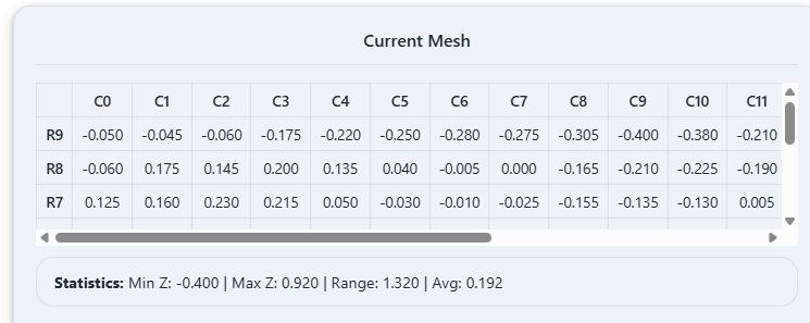
My plywood sheet was about 500x900 and this is the resulting surface profile. The Z variation is 1.32mm
For the first tray done without the height-mapping, the dadoes for the grooves were of uneven depth. This caused issues later during glue-up when joining the pre-cut pieces. As a result, the sides of the tray were a bit wonky. No big deal but annoying for a perfectionist.
By doing the height-map first, all the dadoes were at the correct depth (1.5mm) and the pieces all fit in nicely.
@Chucky_ott Thanks much for the process report, CO. It’s on my winter bucket list to try the height mapping process. You have inspired me to get off my butt and actually start playing with it.
@Jens Maybe 10 minutes for the 200 points spaced about 50mm. But I could easily have increased the speed. The default in ncSender was 3000 ( I forget the units) and I had increased it to 5000. I could have gone even higher but this was my first time using it and I wanted to get a feel on how it worked.
Chuck, you outdid yourself. Sure the poject is simple and the solution is complex for such a simple project, but when successfully pulled off, it opens door to so many applications.
I like the approuch and the fact that you showed it off here. This would be a game changer for pretty much every project I engage. I now have to way having inconsistant in depth of my carvings or include a surfacing toolpath. Both options have me being reluctant to choose between, yet I mostly have to regardless.
This probing step might bring joy where I normaly indulge in fear reviewing the flatnes of my stock on the machine. I do so like to keep away from surfacing natural weathered surfaces. A surface that looks weathered, adds age to the whole.
For someone who likes to make believe my projects may possibly be hand crafted, being able to include your novel approuch would be a powerfull addition to my skillset.
Yes, I look for imperfection, the oposite of what you are looking for. Guess what.
Avoiding surfacing weathered wood was one of the main reasons I got it. I did a few signs for weddings and had to surface the wood before because they were uneven. Now I won’t have to. I delayed buying the probe because the mesh feature isn’t available in gSender. Hopefully it will soon.
But it’s hardly my idea. The mesh feature exists in a few senders, likely because others have requested it for this purpose. I just posted here with details for the benefit of other with the same issues that I have encountered.
I just ordered myself a simple capacity sensor to experiment with. I do not need a high resolution sensor, nor do I need xy capability. Because the discrepancies I encounter are mostly gradually over the surface of the project, think I can cheap out on the sensor and call it a winwin.
I’m going with this here cheapo (only €13 give or take $15)to engage a proof of concept. Keep ya posted (in due time cause I am a slow moving slug when it comes to pocs)!
@Spamming_Eddie OK, now I need an alias for you too. That sensor looks like a good idea for just a surface mesh, depending on the accuracy. 0.1mm would be satisfactory. Not sure if I’d be happy with 1mm. You could attach a ball bearing at the end to ensure a point contact.
The range you mention is the dectection gap between the sensor and the material, not the accuracy. The gap detection height can be set with a setting screw at the back of the sensor. How consistent it will be is part of the experiment to show. It might fail on that or other variables , and that’s why I am going with this bulky sensor and not with the industrial types that have a way smaller sensor head (and cost an arm and a leg.)
This experiment is a long shot, but I can use the sensor for other purposes, if it can’t produce anything useful in this application. (Think auto z zero for my laser, that does not need to be micrometer accuracy.)
How long did the surface probing take on a tray that size, and did you notice a real difference in depth consistency compared to the first one you made without the height map?
Late to the thread, but following with interest. Would a sensor typically used for a 3D printer (like the BLTouch sensor) be suitable? I think they can be a lot less expensive - I’m seeing 25 to 30 CAD on Amazon for BLTouch clone sensors.
I’d like to be mistaken about this because I can see a BLTouch to my left but I have my doubts. At least I don’t think it would be easy.
First I’m not sure how to wire it and from looking that up I think if it can be done with a SLB/-EXT it would require compiling the firmware with some changes. Also I’ve only seen the codes to control it in printer firmware.
If those things can be solved I don’t think gSender would be able to use it without modification or a plugin. The printer mine is on has been dead for years but I think it worked like this. After a self test it extends the pin then it moves down until the pin pushes in and trips the hall sensor then it retracts the pin and moves up. That seems like a couple of steps that gSender doesn’t have to do with a touch block or 3D probe.
I’m not really experienced with this kind of stuff so I hope I’m totally wrong.
EDIT: After reading @Jens post below I’ll say I don’t think this would be a good use of my time. I think the inexpensive 3D probes are around 70USD and I’d rather get one of those and be done with it!
I also forgot about macros when I said gSender might not work as is. Oops!
I suspect (but don’t know) that this can indeed work. There are 5 wires that the BLTouch uses. Ground (*2), 5V (if the BLTouch is a 5V version), a PWM ‘Signal’ line and the output of the probe. The ‘Signal’ line is a PWM control line that is used to raise or lower the probe pin.
The SLB-EXT has all these lines available. The laser control on the SLB-EXT is a PWM output.
To sum it up, the SLB-EXT has all the inputs and outputs available to control a 5V BLTouch sensor but the question will be ‘can you control the laser control output with sufficient accuracy for everything to work’ and I am afraid I can’t answer that question. In any case, it isn’t a simple ‘plug and play’ solution. Is it worth it to save a few dollars rather than buying the right tool - probably not but hey, you do you
When I responded yesterday, I swear I only saw it as a 3-wire probe. But I’m retrospect, now that I have seen @Jens’s and @_Michael’s responses, I have to agree that it would not be worth the time to save a few bucks. Maybe if I already had one, I’d try.
Good point on the time required… yeah I don’t already have one in hand. I do have an assortment of old 3D printer parts, including an optical homing switch - might not be complicated to 3D print something it could go in to do probing.
Out of curiousity, what sources are people using for the real probe above? I see them on Amazon, AliExpress, etc…