when i load my file for cutting it is displayed on the main visualizer correctly and the X, Y, and Z are set but instead of cutting the file it just start cutting almost at the X, Y, Z position. I was cutting other portions of the model yesterday and today it just wants to cut in the lower left corner of my board. Not sure what has happened since yesterday.
@LarryLSimmons Can you confirm that you are using UGS as your code sender? You have posted this in the UGS category.
Also:
- What machine do you have?
- If it is a Sienci machine, what model is it?
- What CAD/CAM application did you use to create the toolpaths and gcode?
- What post processor did you use to create the gcode?
I may have posted this in the wrong place. I am using Gsender. I have an ALTMILL 4X4 and i built the model in CARVECO. Everything worked fine yesterday and today it isn’t.
@LarryLSimmons I’ve moved this to the Carveco board as it’s not possible now to know if this is a carveco issue, a gSender issue or a machine issue.
I know that it sounds argumentative, but can you back up and see if you can determine what changed since all was well?
If I am reading your original post correctly, although other files ran fine, the one in question is not. Correct??
If that is the case, it would seem to be a file issue rather than a carveco or gSender issue.
I have never used Carveco. Can you re-calculate the toolpath and re-process the gcode?
Yes, i will try that. i have two models that use the same type of vector and it is happening on both of them. I will recalculate the tool path and try again. Thank you.
So I recalculated the tool path and reloaded it. The tool path in the main analyzer is correct but when I run the outline of the tool path and run the outline it just makes a tiny outline of one of the tool paths in the corner. There are 12 tool paths for this model. all of them ran correctly. just this one doesnt,
I will go and delete the toolpath, regenerate it again and see if that resolves the issue,
@LarryLSimmons Some users that have reported a size discrepancy in the visualiser had a metric/imperial conversion issue. Did you double check the units in Carveco and gSender?
Perhaps unrelated, do you use the appropriate post processor? Even if you design in inches and display in inches in gSender, it’s better to use the grbl-mm post processor. The conversion is done in the background.
I rebuilt the tool path and have the same problem. I ran the outline on several of the other tool paths and it worked just fine.
Thanks Chucky. the problem is that all of the other tool paths work just fine. I just ran several outline tests of them and they were correct. It is just this one tool path that wont work.
@LarryLSimmons Hmmm. The same Carveco project has different toolpaths and one of those toolpaths displays tiny in the visualiser?
this is a profile tool path. it looks fine in the visualizer. when I hit run it just starts carving in the lower left corner. almost at the XYZ coordinate. and it is tiny.
@LarryLSimmons Do you want to post the g-code here or sent it to me via the internal messaging? I can take a look at it in my gSender (but likely not before tomorrow morning)
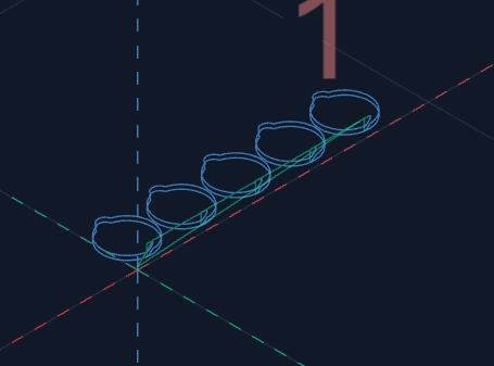
here is what it looks like in the visualizer. not sure how to copy the g- code out of gsender.
@LarryLSimmons it would be whatever you exported from Carveco. By looking at the grid and the big “1”, it looks like that entire job is 1" wide. How wide should it be?
they are like 3.5 inches tall.
i am not sure why they are showing up so small. the other files show up the correct size
@LarryLSimmons But what is the total width of those 5 parts? If you tell me about 25", then I’d respond back with the units issue (1" = 25.4mm)
each one is approximately 4.25 inches wide. not sure why they are showing up so small