In Vcarve pro. I’m trying to create a contour from an irregular object in the center of the workpiece to the edge of the workpiece. I tried using the Chamfer toolpath, but it isn’t able to handle the variable distance to the edge very well. Then I tried moulding, which can give me a better profile to the edge, but again I can’t see how to handle he variable distance to the edge.
What I would like is for it to gradually contour out to the edge, leaving almost zero depth at the edge all the way around, or maybe 1/16” at the edge.
I’m wondering if that can be done in Vcarve pro? Maybe I need Aspire to do that or some other 3D software?
If I understand what your trying to do, you want a taper from the inner shape to the outer shape. If this taper is straight then I think @Chucky_ott’s suggestion to use a separate 3D package that has a ‘loft’ function is the way to go.
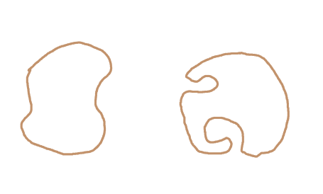
Fusion is a excellent program but isn’t free for commercial use. If that matters to you FreeCAD has a loft function. Shapes with ‘occluded concave parts?’ won’t work for a loft. Not sure about the terminology so here’s a pic with a shape I think is okay on the left and one on the right that I think would cause problems with a loft.
The actual process will vary with the 3D program but in general you’d want to export your profiles as svg files and import them into the 3D program. You want the inner shape to be above the outer shape by the thickness of your stock minus the 1/16" you want to leave. Then you create a loft from the outside shape to the inside shape, export that as an stl file then import and position that in Vectric to create the 3D toolpath.
Thanks, yes I struggled with how to describe it! Been trying to find a picture of something similar, but can’t find that either. haha.
Let’s say I have a 2” thick piece of wood, 10” x 10”. I have an oval in the center of the piece of wood that is just flat. From the edges of that oval, out to the edge of the wood, in all directions, I want it to curve/slope to zero. Sort of like an upside down bowl, except it doesn’t end in a circle at the edge, it ends in a square. At the corners of the square piece of wood, the slope from the oval edge to the workpiece edge might be 5” or something. From the middle of the piece, the slope from the oval to the edge might only be an inch or so. Just contouring from the edges of the oval out to the edges of the square work piece.
Oh, this gives me some useful info.. That you want to create svg files to import. I think I can import those to Vcarve. I know how to use inscape, which is a vector drawing package, so that might work. Nothing I do is commercial, so might also be able to use Fusion but I also have Freecad loaded on my machine.
All this gives me some good things for direction. I have just ordered an Altmill, and in the “waiting for delivery” period I’m working on some things I want to do. I also just recently had surgery and am limited right now, so I’m spending a lot of “chair time” which gives me a good opportunity to do a deep dive into some of these programs. Thanks for the help!!
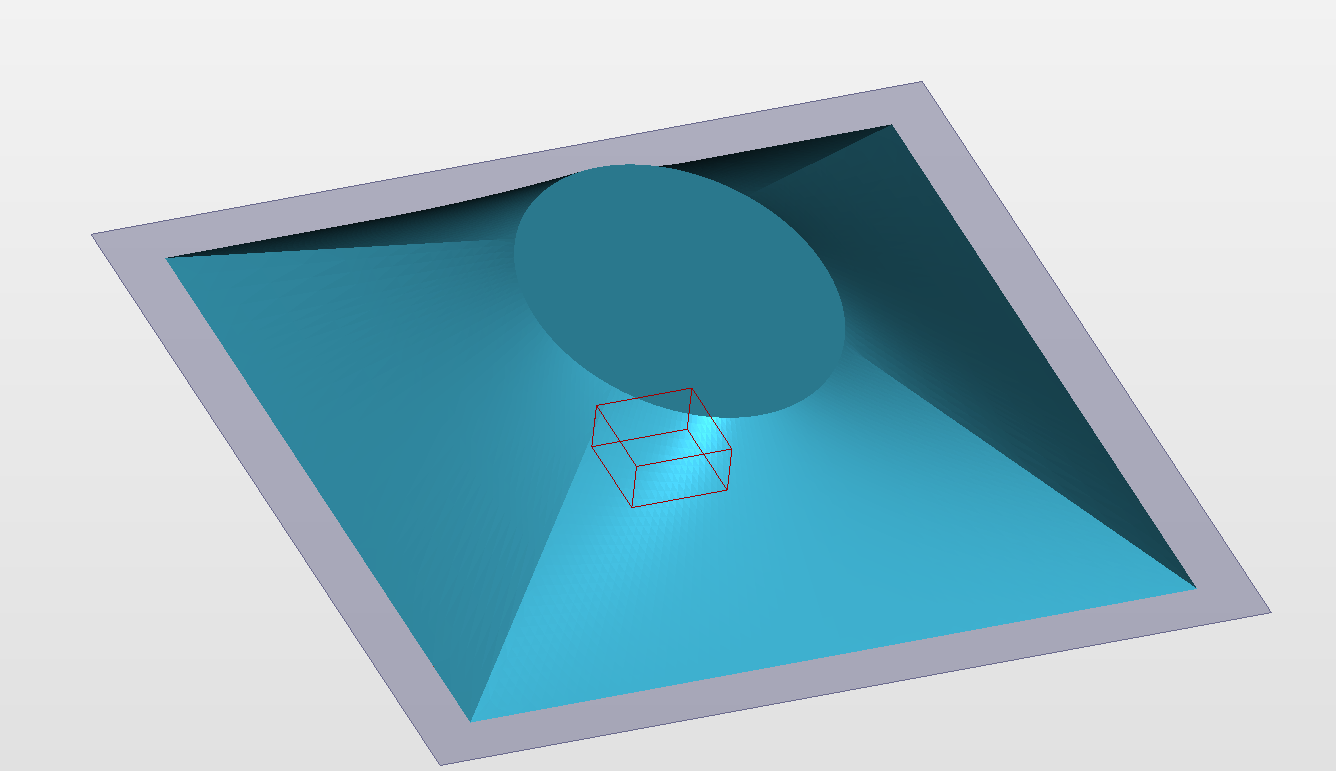
Thanks. That’s more of a chamfer, which I have pretty much figured out. Actually for this one I’m using the moulding toolpath in Vcarve, so I get a curve instead of a straight chamfer.
But I would still like to get the hard diagonal lines between the X and Y directions smoothed over and I would like to get it curved more at the bottom end such that the edge contours to zero all the way down.
Ah, so I could make another toolpath that clips that off. That’s something for me to figure out. Actually I’m sort of liking the look of what I have. I will have to wait for the machine, then cut a prototype, mount my speakers in there and do a bunch of testing to see how it performs. It might be ok.
Thanks so much you guys for all the help!! Great forum!
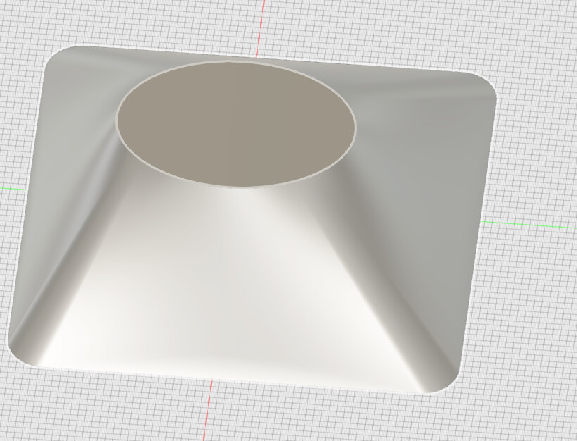
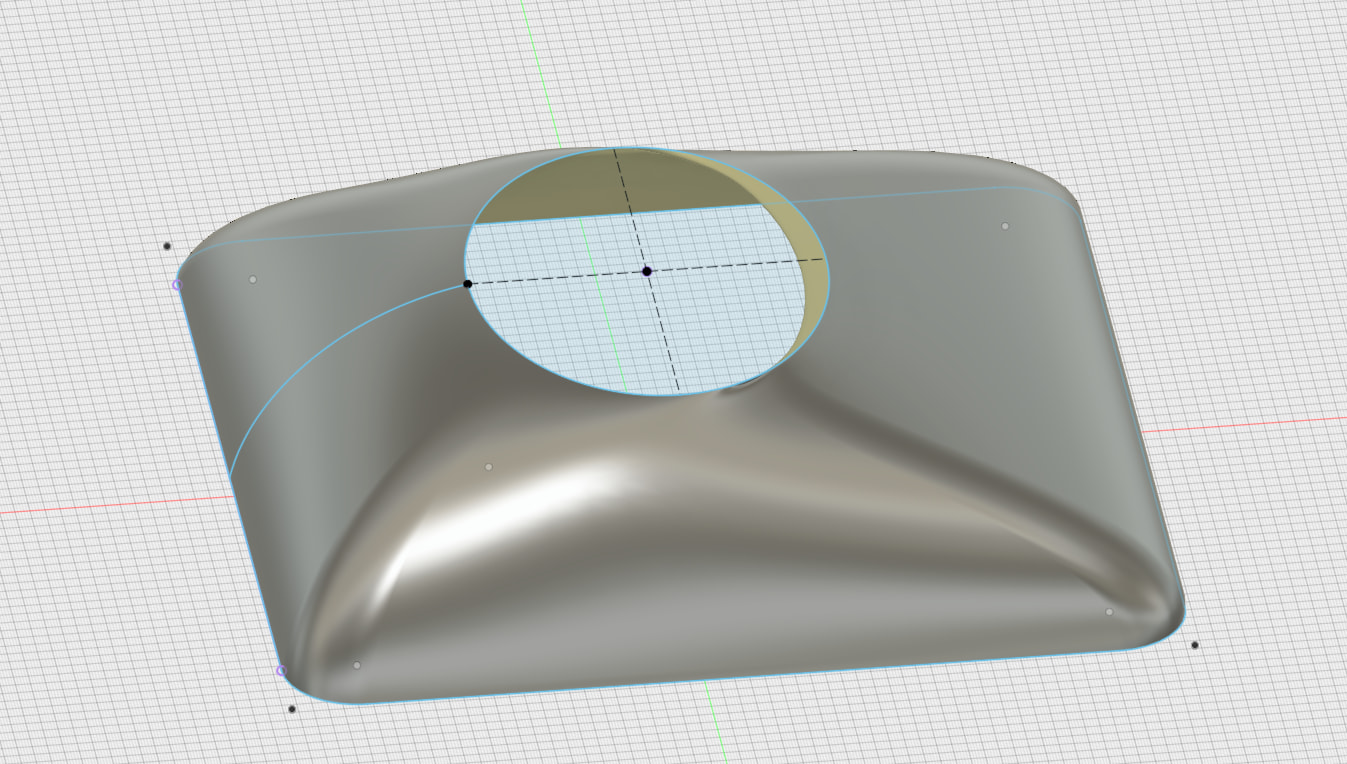
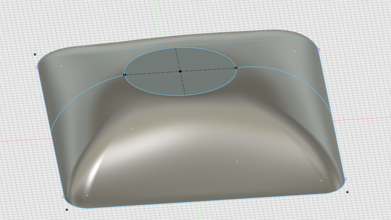
@gabo Also, by adding a “rail” to your Fusion “skeleton”, the loft surfaces can follow a specific path. In this case, I added an arc between the square and the oval. and made the loft follow that arc.
Ah, that’s getting there, very cool. I don’t see a way to do those types of things in Vcarve. But no worries, I need to go learn some things in Fusion and Freecad anyway. I realized before I purchased the machine that this is not really about the machine, it’s about being able to create things in the CAD/CAM packages. If you can do that, the machine will do what it’s told to do!
How do you get Fusion or Freecad to control your machine? Or do you import those drawings into something like Vcarve and then build your toolpaths?
@gabo Fusion has the ability to create toolpaths and g-code from your model. You then use Sienci’s gSender (or another g-code sender if you prefer) to send the g-code to the CNC. In other words, Fusion doesn’t interface with the CNC directly. You still need a g-code sender to do that.
I prefer to import the model created in Fusion into Vectric vCarve and do the toolpaths there.
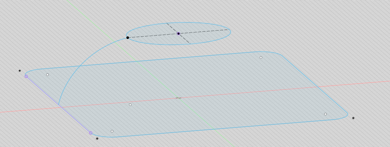
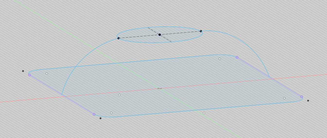
@gabo BTW, in the example above, I show two sketches, each on a different plane, and two arcs to join them together. These are then used when using the loft command. But I could also have done it with three sketches on three different planes and not use any arcs. Fusion then decides how best to create a surface that passes through each sketch. Sometimes, the results get interesting.