Hi there, I just finished putting the Altmill 4x4 together. I’m new to CNC and just have a few questions to get to know this machine better.
I was expecting physical limit switches on both ends of each axis to prevent crashes - am I right in assuming that the closed-loop stepper controllers act as a limit switch here? In other words - in case of an error the machine would “crash” in to the rubber bumpers and trigger a stepper controller error when it can’t move any further? What about the Z axis (no rubber stops)? (I understand that homing on startup and correct max travel in firmware settings should usually prevent this)
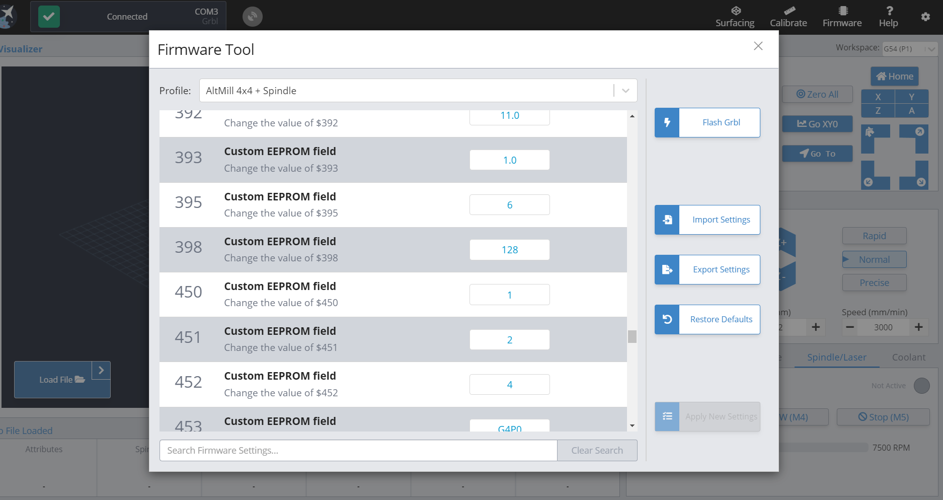
In the video tutorials, G-Sender’s firmware tool has descriptive names for all the $ settings (at least the ones they show in the video). But when I tried to change my default spindle, my $395 setting, and all the $ settings after 133 are all just called “Custom EEPROM field”. I did select Altmill 4x4 + Spindle as my profile. Could this be a bug? The spindle works but I’d like to really get to know this software and how it works.
The altmill has physical limit switches but I can not recall having seen a CNC setup where these switches actually directly interact with the motors/power in order to prevent an actual crash. They talk to the controller and it is the controller that acts on that input.
There are many scenarios where the controller raises an error condition and shuts down the motors. Hitting an obstruction (such as a bumper or maybe a fixture clamp) is one reason.
The physical zero position is slightly off from the rubber bumper. If everything works as it should, the rubber bumper would never be bumped. Alas, crap happens and that is why you have a bumper.
The z axis has the limit switch but you are right, there are no bumpers. Guessing on the reason, I would say the axis has very little mass and is relatively slow speed so a bumper would likely not be needed.
Regarding the second question - yes, it’s annoying that a field is labelled ‘custom eeprom field’. I wouldn’t call it a bug, it is done on purpose for some unknown reason. There might be documentation available for these entries but I am not aware of anything - ask Sienci tech support and maybe they can help or explain why there isn’t a better field description.
I can only chime in on part of question 1 as I own a LongMill without the SuperLongBoard.
That is why only one switch per axis is needed. Once the machine is homed it knows where zero is and that it can’t go beyond the max travel for that axis. Of course my machine does not have closed loop steppers so if something caused me to lose steps then my machine could still crash. That shouldn’t be a problem for you with the closed loop steppers on the AltMill.
Be safe, the AltMill is a beast compared to the little 3018 that I made my beginner mistakes on. Now I only have to worry about non-beginner mistakes.
You need to connect using the grblHAL firmware, not grbl. I can see in your screenshot you are using the wrong controller. That is why you don’t have proper descriptions. It’s not a bug, just user error.
Don’t believe them…the ONLY thing that prevents this machine from slamming into those bumpers is the inductive sensors. There ARE NO LIMIT SWITCHES…do YOU see any? I know this because the very first thing I did was crash my Z into the ball screw at the top because my inductive sensor was not sticking out enough…and no, there is no rubber bumper. They tell you to make sure the sensor is behind the top of the pocket it is in but that is bologna…the ball screw passes well beyond that surface and so your sensor should stick out beyond a bit…because the ball screw passes WELL beyond it. Testing it effectively manually with a piece of metal as prescribed is just plain useless…you need to manually jog Z up till about 1/4" of the guide rails are left visible at the top…at this point your sensor should be tripped. If it isn’t, jog down and adjust the sensor outward and repeat. I did not see a single visible limit switch anywhere…and there is exactly one inductive sensor on each axis.
The confusion started right with DoNt BeLiEvE tHeM!!1
I like my thems to be a bit more specific. Did you ment all the posters trying to help out in this thread like micheal, jens and kgn. Or is them only one of them representing a greater evil and are you trying to warn we are being invaded by aliens, trolls or worse, a wef like entity?
Are they trying to have us crash our machines so we will keep buying new ones, thus depleting our planets resources before we can become a space faring civilisation.
Or is this a elaborate scam to somehow get us pure bloods to get a vacination against our will so they can kill us with their evil 5G signals like they did with all the sheeps that took the bait the first time.
It’s a diversion from the fact that we never landed on the moon, I knew it!
Is it the reprillians? It’s the bloody reptillians again, isn’t it!
Who is them and what is it they are trying to make us believe?
“Them” is the people that keep refering to an inductive sensor as a limit switch. Its like refering to a “pressure sensor” sensor as a safety valve…its just not true and it is misleading. Even sienci labs eludes to “limit switches” that are nonexistant. So yeah, dont believe them…
The inductive sensor switches gnd to a pulled up pin when triggered. The controler reacts to this input by stopping the movement in the direction of said sensor. I call that a limit switch too.
@Spamming_Eddie@softwareguru OK, guys, I’ll leave the last couple of posts, but please keep this on topic. I will delete these posts and any others that continue in the same vein.
Let’s stay friendly and informative, please.