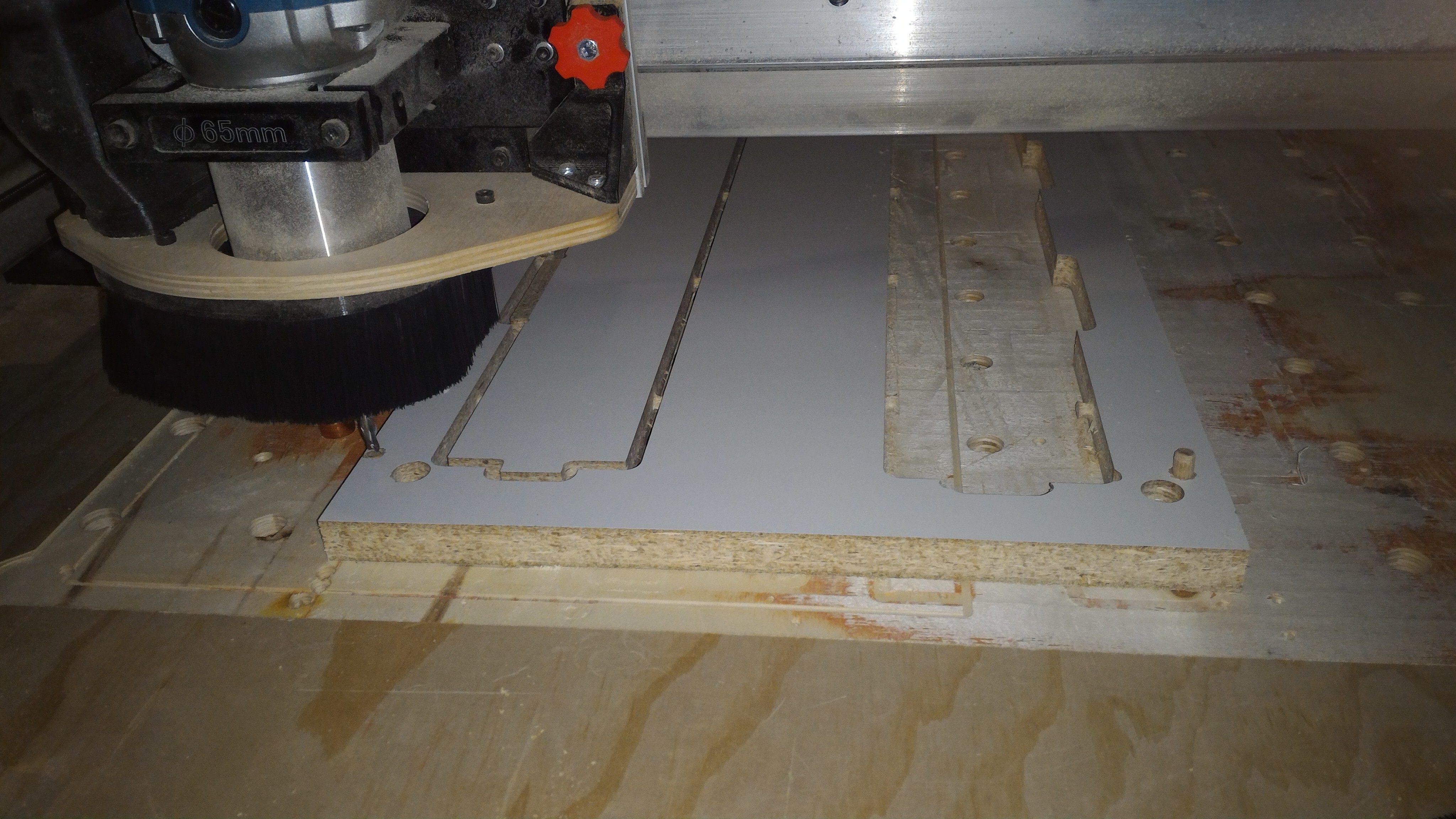
Hello. I was trying to cut using the double-sided method:
I cut half thickness on one side.
I flip my stock using indexing pins and dowels.
Finish the cut from the opposite side.
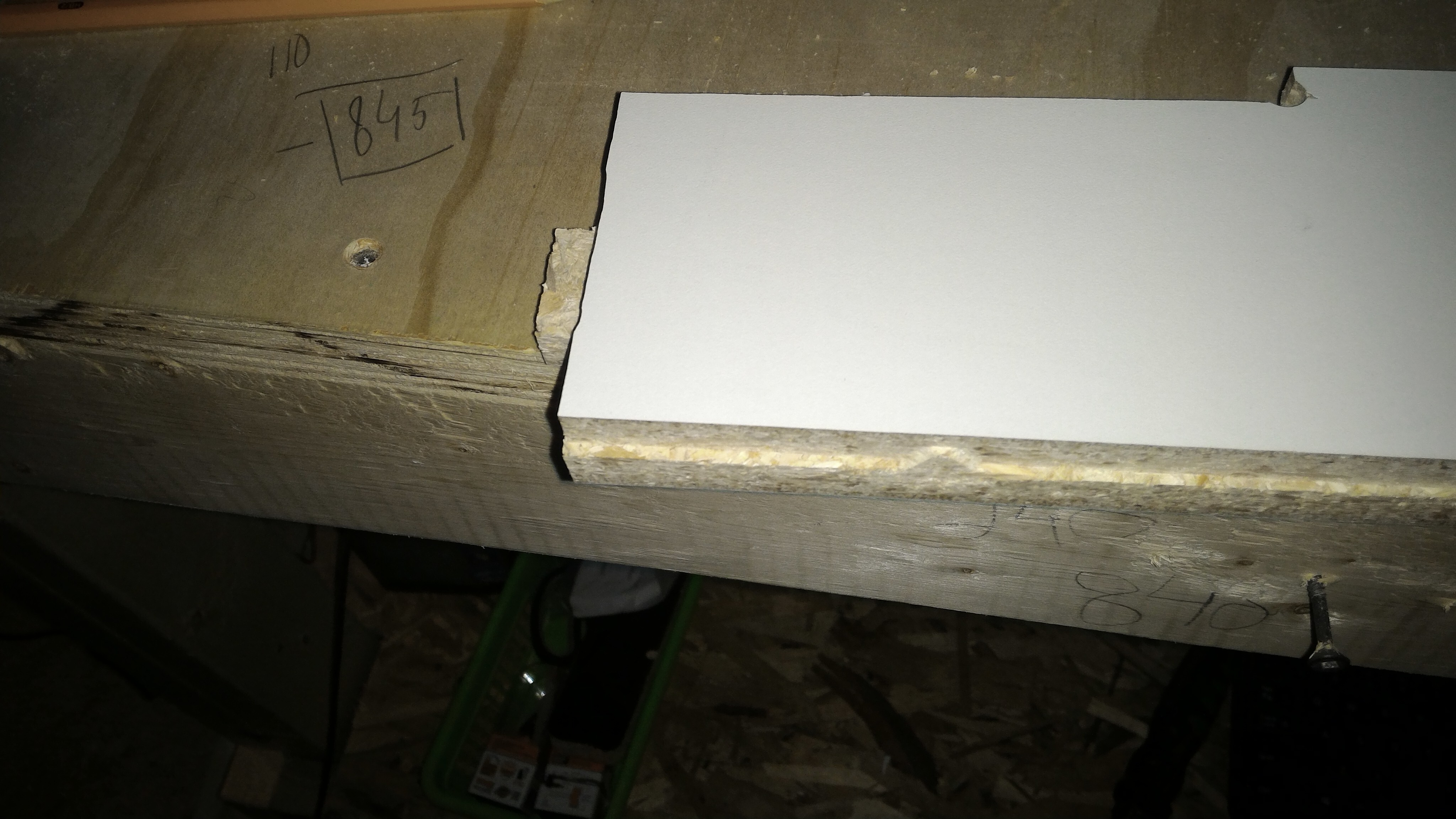
Every time I finish step 3 I end up with relatively matching pockets on both sides, but my contours are always off at least 2 mm on the side away from the indexing pins and 0.2mm on the side towards the pins.
I have tightened V-wheels and back-lash nuts on the y-axis. X-axis does not have much wiggle. Also, I have found, when I run the Y-axis to the far most position. The right gantry toches the rear foot first compare to the left. Adjusting that did not solve my problem.
I will gladly hear any suggestions, how to get the perfectly matching cut.
Is your WCS zero set in the same place on both sides and is that place on one corner?
Could it be that the work piece is slightly different than the defined stock in your CAM program and when you flip it you introduce error that is half the error you’re seeing (with the other half being on the side you already machine)?
What software are you using to create the two related toolpaths?
Another thought, have you tried turning the job 90 degrees and doing it exactly as you are now to see if there is a difference working in the other orientation?
Hello, Jeff.
I am using Fusion 360.
So, my first origin is on the left front corner of my stock. When I flip my stock I have to change my setup and move my origin back to the left front corner of my stock. The first origin gets flipped and becomes right/bottom/front corner of the stock.
I have measured my stock and created a model with exact distentions.
And Yes I have tried to cut along X-axis instead of Y, but it did not change the result.
Ok it sounds like you’re using a single work piece and running the exact same operation twice, just flipping the stock over physically, is this correct?
I’ve only done index/tiling with a longer piece, but I did spend some time thinking about doing a top/bottom operation like you are. I am also using Fusion 360.
Are you using four pins, one in each relative corner area? Would you be able to share your Fusion 360 model/setup so I could look at it for you? Maybe send me a dropbox link or similar file share if it is large?
Yes I am using single work piece. Operations are slightly different cause one side has two more pockets.
I have done index/tiling before on longer piece it was not ideal(may be 0.5 mm off), but I was ok with this because dowels are not that rigid.
I am using two pins and fasten opposite side with screws.
I am using 5/16 dowels (8.2 mm holes diameter).
To cut holes I was using “Bore” operation with default settings and 1/4 down cut bit.
Dowels sit tight, even with no screws on opposite to the pins side stock barely moves.
@Helix05 Andrey: I have done several picture frames using two sided milling to get the rebate in the back for the art, then flipping to get the frame profile and the cut outs. So far, they have all worked. (I say all this nonsense just so you know that I have some experience with two-sided milling. )
One thing in the description of your process has me confused is when you talk about setting origin. To make this work, you only set X0Y0 once. They never change after that. Z0 will change to drill the holes in the spoil board.
Can you clarify what you are doing? I’m a bit slow.
My process is this. I set XYZ0 on the back surface of the material. I do the back side first as I will be cutting out from the front. I drill two locator holes in the material, then cut the art rebate.
Then I remove the material, set Z0 on the spoil board, and drill the two holes in the spoil board. X0Y0 do not change.
I replace the material on the locator pins, flipping it side to side. (I use VCarvePro and you must choose in the CAD setup whether to flip top to bottom or side to side.)
I reset Z0 onto the top of the material and cut the top tool paths. Again, just to be a nag, X0 and Y0 do not change.
Mark Lindsay has an excellent 3-part Youtube series on this, which he just did recently.
He did share his model with me and I was in the midst of looking at it for him and he disappeared. Haven’t heard from him since. Not sure what happened.
He was doing it in an unusual way with the way he was moving his XYZ zero. I would do it the way you described and leave zero alone and move the work piece. I was headed towards showing him how to do that when he went poof. Also had some questions about his stock sizes, they were different references for the two matching jobs which didn’t seem right to me but I didn’t get to the bottom of that part.
Later on this week, once I finish cleaning up this sensors project, and after I take a look at the drag knife project, I think I’ll try to do some double sided work in F360 and make some notes for future reference. Great program but almost too flexible/powerful sometimes…
@jwoody18 Sorry, Jeff. For some reason, when I replied to Andrey, I didn’t see your replies. I’m sure that I was just not looking. I’m sure that you have his problem in hand and that neither of you needs me kibbitzing. I’ll leave my post here, only because you have referenced it and it would be weird if I removed it.
Looking at the preceding posts again, I must really have been asleep. He said that he is using Fusion360, so any of my advice within the context of VCarvePro is useless to him.
Hello and I am sorry again. Forum has a bit strange policies for newbies. Thank you gwilki!!! I have tried to recreate similar setup in Aspire. This time it turns out better, but still I have a little gap on one side (approx 0.3 mm). I would like to try add more pins to increase rigidity. I if it works, I will be able to call it a day.
Hello, Jeff. I have tried different stock setup. I was getting the best results by creating a sketch and extruding it in three dimensions to fit my stock. Next, I nested my part inside the virtual stock. When I was making a tool path a picked both(the stock and my model) and choose relative size box with no extra stock.
I hope this is make sense.
Thank you for your help.
@Helix05 You can certainly try more pins, Haley, but if the 2 that you have been using are tight, I don’t believe that adding more will solve your problem. As for me, I’ve never used more than two.
I re-read your first post. Why are you cutting half the thickness from each side, rather than cutting all the way through from one side? Yours is not necessarily a bad approach. I’m just curious as to why you have chose to do it that way.
A couple of other things: Since you have Aspire, I would suggest that you not use the drilling function for your locator holes. Use a pocket tool path and pocket to about half the thickness of your material. If you want to use 5/16" pins, use a 1/4" upcut bit and ramp in by about an inch. Do not use a downcut bit. There is no place for the chips to go and you risk burning. Do the same thing for the holes in your spoil board.
What bit are you using for your cut out? I can’t tell by your pics. Since you want to cut half the thickness of your material from each side, be mindful of feeds and speeds, especially if you are using a small diameter bit. Too fast and the bit will flex, maybe giving you the problem that you have.
Thank you for your response. I’m cutting white melamine. Since I’m using down cut bit and my models have double sided features I thought this will be reasonable approach to avoid any chipping. I tried to use compression bit from Amazon but they are pretty expensive and the one I bought got dull after few cuts. In order to cut my indexing holes, in Fusion 360, I was using bore procedure. Aspire has drilling function but I don’t have the right diameter drill bits, so I was using pocket procedure as you described. One more think I have noticed yesterday , I am missing x axis backlash nut. Wiggle on x axis is minimal, since my machine is one month old. I will try to fix this problem today. Lastly, I am using one quarter down cut bits for majority of mine beginners projects. Thanks again for your participation I really appreciate your help.
Andrey.
@Helix05 Given your requirements, Andrey, your approach makes sense. Using a 1/4" bit, you should not be getting much flex so long as your feeds and speeds are reasonable. One thing to be mindful of is ramping. You can eliminate a lot of “edge” issues by using relatively long ramps.
Here is a video by Mark Lindsay on the topic:
Clearly, installing and properly setting a backlash nut on the X axis is a must.
Thank you, Grant. I was going to explore this option, but my learning curve is really flat. Unfortunately, I have only about an hour a day playing with my machine. I will definitely take a look. Thanks.
 )
)