The following might be a Fusion issue or more likely an operator issue:
I have a small test object, double sided with two alignment pins
I set my origin at the bottom left corner of the model. I first bore the holes for the alignment pins - through the test object and into the spoil board.
I then go ahead and machine the top side, flip it over from left to right along the axis of the two alignment pins, insert the pins and attach it to the spoil board. Since the stock piece is not symmetric, I do not touch either x/y or Z.
In Fusion, the origin was is set to the left bottom corner again.
When I run the second side, there is a slight (maybe 1 mm) registration error between the top and the bottom and I can’t figure out why this is.
I am assuming that I am not understanding something and I am setting things up wrong. I am thinking that once the alignment holes are bored in the work piece and in the spoilboard, nothing matters as long as I don’t touch my origin coordinates and as long as I flip the work piece along the axis of the alignment pins because the alignment pins are always in the same position relative to the model origin.
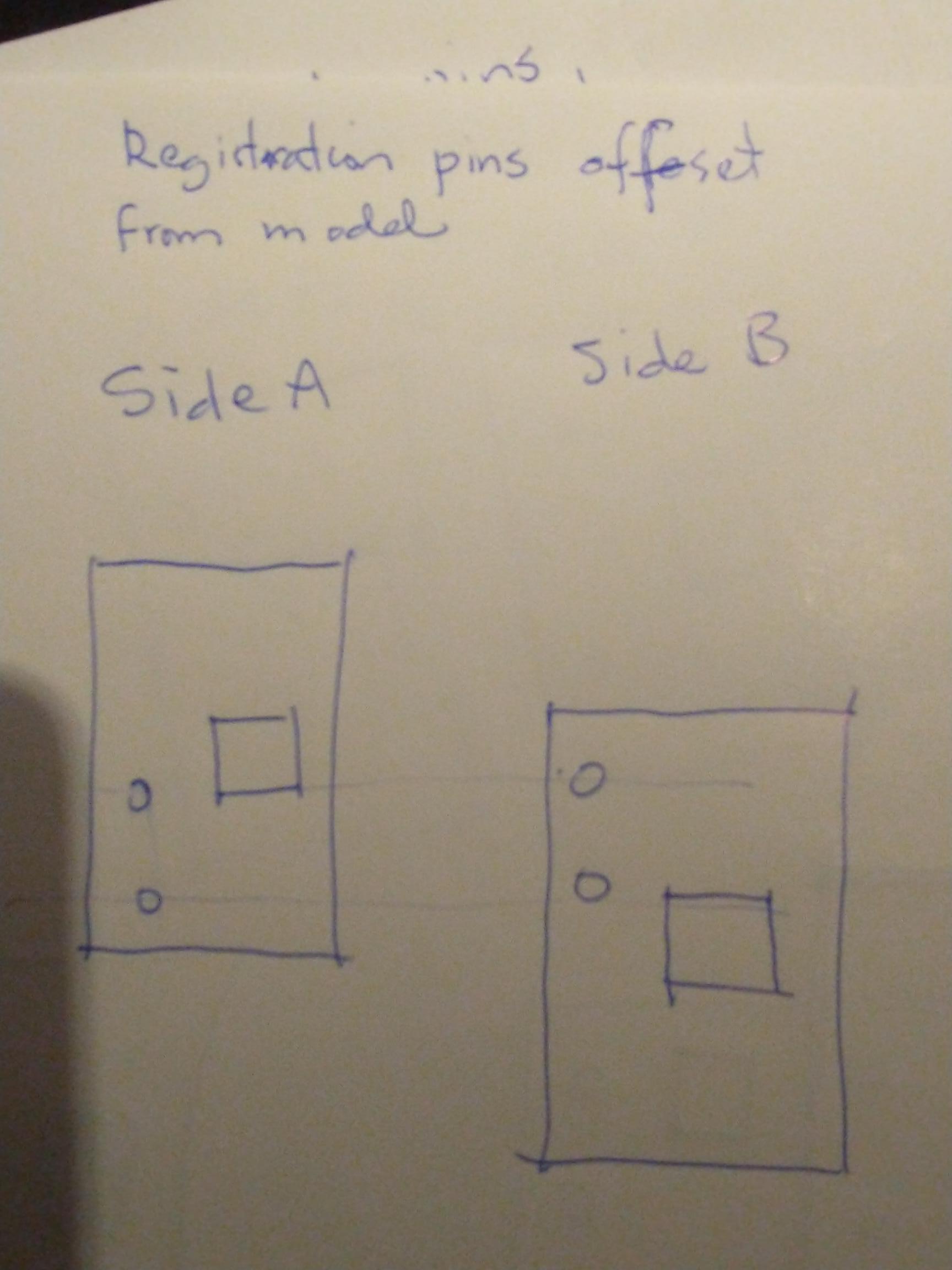
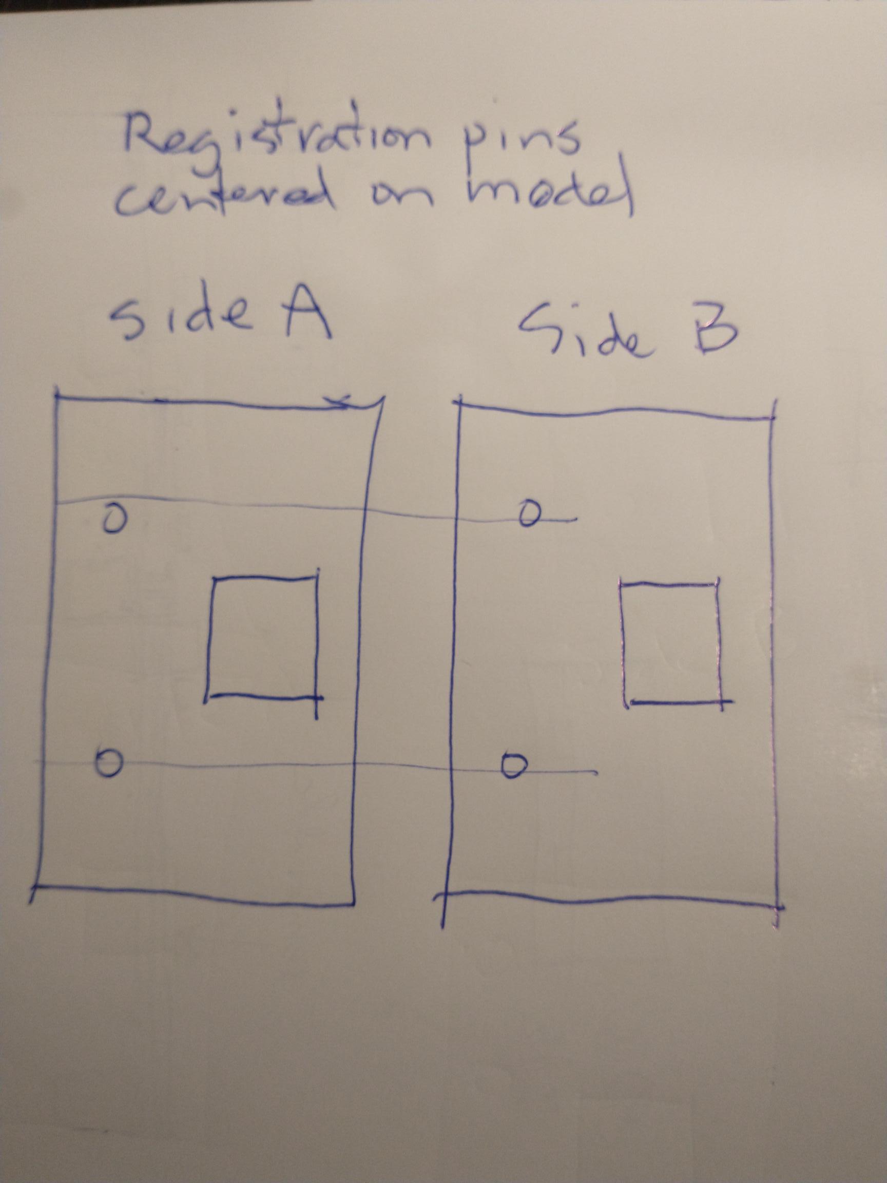
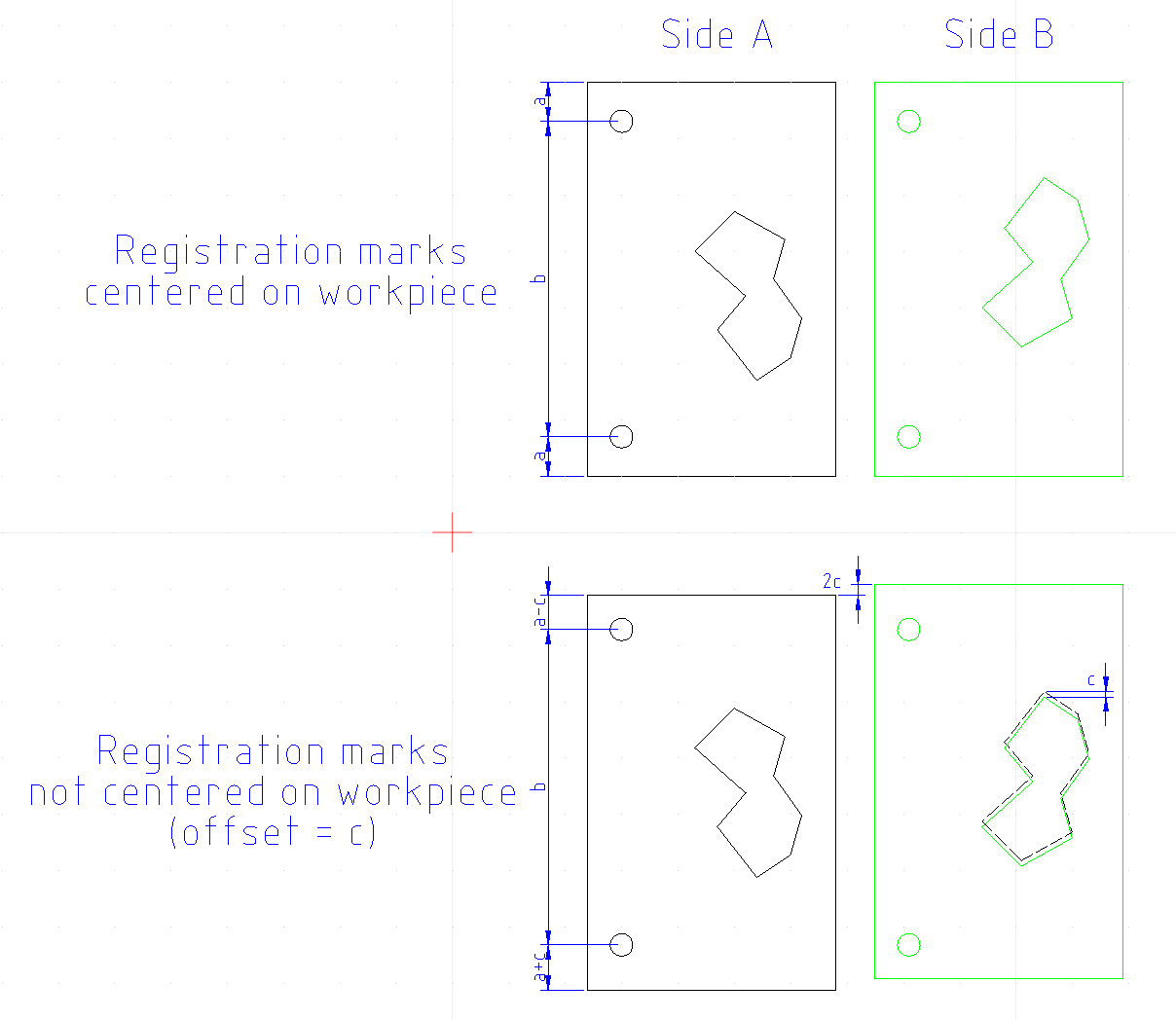
Edit: I’m pretty sure the statement below is incorrect. In fact, I now think that the registration marks need to be centered on the workpiece. While easy to do on the model, it might be difficult to accomplish in practice unless you can position your workpiece fairly accurately on your spoilboard.
Original message:
I think I understand your explanation. I would think that the registration marks on the model would need to be centered on the model. Any offset would would show up when you flip it.
Yeah, I am having a hard time figuring out what exactly needs centering and what not. After large magnification, I just found out that the registration holes were not quite on the centerline of the model and that could very well be the problem.
I will re-draw things and run another test but I am having serious issues wrapping my mind around this.
@Jens I don’t know about Fusion, but in Vcarve, I don’t cut the holes in the material all the way through. When I am finished with the top side, I remove the material. Then, I drill holes in the spoilboard. These holes are the mirror image of those on the top side. They are not simply the top-side holes drilled through the material and into the spoil board. Since my holes are not symmetrical, they are, in effect, the opposite of the material ones.
When those are drilled, I put dowels in them, then flip the material and press it onto the dowels. This works everytime
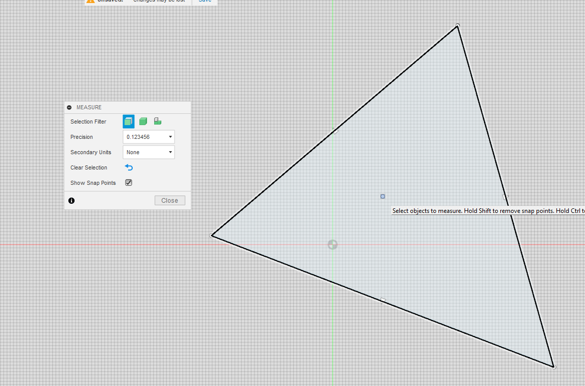
@Jens In Fusion, you can find a face’s centre by selecting “Inspect” and enabling snap points. You can then get an accurate value for the centre and move your model accordingly
@gwilki@Jens Grant’s method is the better way of doing it and doesn’t require any measurements. If you don’t have vCarve, I’m not 100% sure how you’d use that method in Fusion. Having never done it, I think you need to find a way to flip your model and then drill only the registration holes in the spoilboard.
I did the run again, corrected for the slightly off holes and the result is even worse.
@Chucky_ott, why do I need to find the center? Do the dowel holes need to be aligned to the center somehow?
I am officially thunk out for today. My brain has turned into mush and I can’t think any more. I will tackle it again tomorrow.
I guess I don’t know what needs to be symmetrical and why.
@gwilki, I will have to think that one through. I always was under the assumption that the holes were supposed to be straight through. Maybe that makes sense since the work piece gets flipped and is in effect a mirror itself.
@Jens There are many good videos showing double-sided projects using VCarve. I realize that you are not using VCarve, but they may help you. Or, they may make what I have said clearer. I’ve done literally many dozens of two-sided projects and never had an alignment issue between the two sides. I take no credit for that. I simply followed the instructions in good videos.
I’ve read all kinds of other ways. None work consistently.
However, if Fusion does not have a function where you copy the alignment holes to the other side - not copy and paste - then I don’t know a fool-proof way of doing these in Fusion.
As far as I know, there is no ‘direct’ way to mirror the holes but I have no doubt that it is possible to do.
I have watched many many videos but limited myself to Fusion based videos. Unfortunately I still haven’t wrapped my mind around the concept of using pins. Up until now, I haven’t heard anything about mirroring the holes but it actually makes sense.
I have done double sided projects but not with pins and doing it with pins could potentially be a much more efficient way of doing things.
@Jens, In trying to better explain it, I just confused myself more! LOL. Now that I think of it, it doesn’t matter that the model is centered on the registration pins. Doing it your way (hole through work piece and spoilboard), what IS important is that the registration holes are centered on the work piece. This essentially mimics the method Grant describes. The difficulty you might be having is likely caused by not being able to place the workpiece exactly as the model expects it to be. Any deviation would cause an offset in the flipped carve. Grant’s method essentially eliminates that error.
This poses a problem. The whole concept for me was to take a random sized piece of stock and being able to flip it without having to reset x and y.
To put it another way, let’s say I have a chunk of plywood with irregular edges. I want to use that stock to make 4 sides of a drawer. What I have been doing is to put the stock on the mill table in any which orientation that allows me to carve out the 4 pieces. The initial stock can have a random x/y zero as long as all pieces can be cut from that initial piece of stock. Once the individual pieces are freed from the original stock, the second side CAM model has a very specific x/y zero spot - let’s say the bottom left side of each individual drawer side piece when turned over.
I can now mount each individual piece on my mill table, one at a time, line it up with a fence on the left side and a fence along the bottom and x/y zero is where the bottom fence meets the side fence. At that point I can cut the second side features because everything is lined up in a way the CAM system expects to see.
My problem with that arrangement is that instead of one piece of stock containing the four side pieces, I have to handle each second side operation for each part individually.
I might not be explaining myself correctly but this makes sense in my mind and has been done successfully.
What I would like to achieve is to take the random sized piece of plywood, as before, mount it on the mill, produce all first side features without separating the individual wall pieces from the stock including 2 registration pin holes. I would like to be able to turn the entire piece of stock over, mount it on the registration pins and cut all the second side features and only then cut each individual piece from the stock. Instead of 5 setups on the mill table (1 for the initial stock and then 4 for each drawer side piece) I only have two setups. All the first side features are cut in the initial setup and all the second side pieces are finished by flipping the initial stock and cutting the second side features including the profile cuts that free each of the drawer sides from the initial stock.
@gwilki, I will do some more research but on initially looking at this, Fusion has a ‘mirror’ feature which should be able to mirror the alignment pin holes somehow. I still need to get that clear in my head though..
@Jens I think this can definitely be done using the method Grant describes. But in Fusion, you would need three models. First model is of top face and registration holes. Second model is a mirror image of the first model but only with the registration holes. Third model is of the bottom face without registration holes. Doing it like this, it would not matter if your wood stock is larger than the model (as long as your machine zero sits inside the wood stock and coincides with the model zero)
I already have all three tool paths …. I just need to figure out the bit of mirroring the alignment holes rather than boring them through the first side and into the spoil board.
I will work on wrapping my head around that tomorrow.
I am absolutely elated being able to report that mirroring the dowel holes in the spoil board resulted in a perfectly centered two sided test piece !!! No x/y adjustment was required between front and back side milling.
The next test will be to do a piece of stock that has multiple individual pieces on it and see if the concept works for that
BTW, I sat through another two Vectric youtube videos - one went to great pains to go through the Vectric software and stopped before showing the output on a mill. Both made no mention of the mirroring of the holes but the second one showed the mirrored holes (I was watching like a hawk) for a second.
I think that since Vectric does all of this automatically, nobody actually mentions this.
The first video showed off some very impressive features of Vectric that I have no clue how to tackle (if it is even possible) in Fusion.
Yeah, vectric greatest features is that it is thus simple to grasp that even I, old fart, can manage to get it to do pretty much anything I need my machine to do - and some.
It’s like turtle programming. Take this line, do that toolpath-type with that bit at this depth. xyz - run.
@Jens I don’t know what videos you watched, but since you’ve resolved your issue, I guess it really doesn’t matter. I should have pointed you to those done by Mark Lindsay on youtube. He goes into painstaking detail on double-sided projects and using alignment dowels.
I could not help with Fusion so I’m glad that @Chucky_ott could. I appreciate that it can do many things that VCarve cannot. I am willing to bet that the VCarve can more easily do some things that Fusion either cannot do or can do with much more difficulty. I’ve done a few projects jointly with people who are wizards with Fusion. They all seem surprised when I am able to duplicate their output. The Vectric forum has members there that can make Vcarve and Aspire do things that not even the Vectric team knew were possible.
Be sure to post your double-sided work, Jens.
Oh, as an aside, in VCarve, XY0 are NEVER reset between sides. You choose to flip the material top to bottom or side to side. Vcarve does the rest in terms of synchronising the two sides.
While this is correct, you started my journey to a solution by bringing up that a mirror image of the dowel holes has to be used on the spoil board. That was really the stumbling block for me all along - Thank You and thank you @Chucky_ott !