I’ve completed the assembly and testing of a drag knife for cutting thin stock like poster board. All of the parts except the bearings and the mounting shaft were cut from 3/8" plate aluminum with a 30x30" LongMill.
The design is a modified version of the Grunblau drag knife available at http://www.grunblau.com/DragKnife.html. The mods were minor edits to the shape and dimensions of the frame and the way the mounting shaft fits into the router. The bearing pockets and countersinks were all designed and post processed in Fusion 360 and all of the operations on each part, clearing, finishing, and contour, were machined consecutively with the same tool, a Sienci 1-flute flat end mill for aluminum. Machining time was about 58 min for the frame, 25 for each bearing holder, and 10 for the clamp. The holes are clearance and tap drill holes for 1/4"-20 and #6-32 screws that were center marked during machining, and drilled and tapped by hand on a mill. The surface finishes on all parts is much better than they appear in the pics due to reflections. None of the machining marks can be felt with a fingernail.
I used Fusion 360 for all of the patterns I’ve done so far because there is an add-in available that raises the blade, does a swivel, and lowers the blade at the corners so the blade does not catch in the corners and rip or chew up the material. It reads a Fusion 30 .nc file and writes an edited version that includes the swivels. It works very well once you get the blade height settings right.
In the testing I’ve done so far, dealing with very thin materials is a bit challenging because it is hard to keep flat and can wrinkle ahead of the blade if the cutting speed is too fast. The blade extends about 0.230" inches, so I would think 0.200" thick material is about the limit. I am re-designing the blade holder section of the frame to allow the blade to stick out a little farther for thicker materials, maybe up to 3/8".
I have videos from two angles of cutting the pattern for the dust shoe sealing plate out of 0.013" poster board at 40" min. I can email them to anyone interested.
Sorry, a couple late night typos - the blade stickout is 0.230", not 0.023", so materials up to about 0.200" thick, not 0.020", can be cut. And the files were processed, not possessed!
Bill, you’re reading my mind except I was thinking about buying one. I didn’t realize you could do something quite this intricate with the LM! Any chance I can get your F360 files?
Jeff, Brian charges for his design files, and I didn’t alter them enough that I could consider them mine, so I can’t distribute the F360 files. But you really don’t need mine - His design is only $5 and comes with all the parts in STL, DXF, and IGES formats. If you’re fairly comfortable with F360 the setups are pretty straightforward. I used one mill for all of the parts, and there weren’t any real surprises. I’d be happy to show you the minor changes I made if you want to make one. It’s worth it just to watch 6061 aluminum being machined, and seeing how accurate a job the LM can do.
I was on the phone when your original post came in and didn’t click through to the site. $5 is very reasonable. I think I may do that. I haven’t worked with metal before though so I’m not sure how successful I’ll be at trying to do the taps etc. I did inherit a virtually unused tap and die set (just local Canadian Tire/Harbour Freight quality) but it should be ok I think.
I was considering ordering some 6061 from Metal Supermarket just this morning so this may be just what I need to click buy.
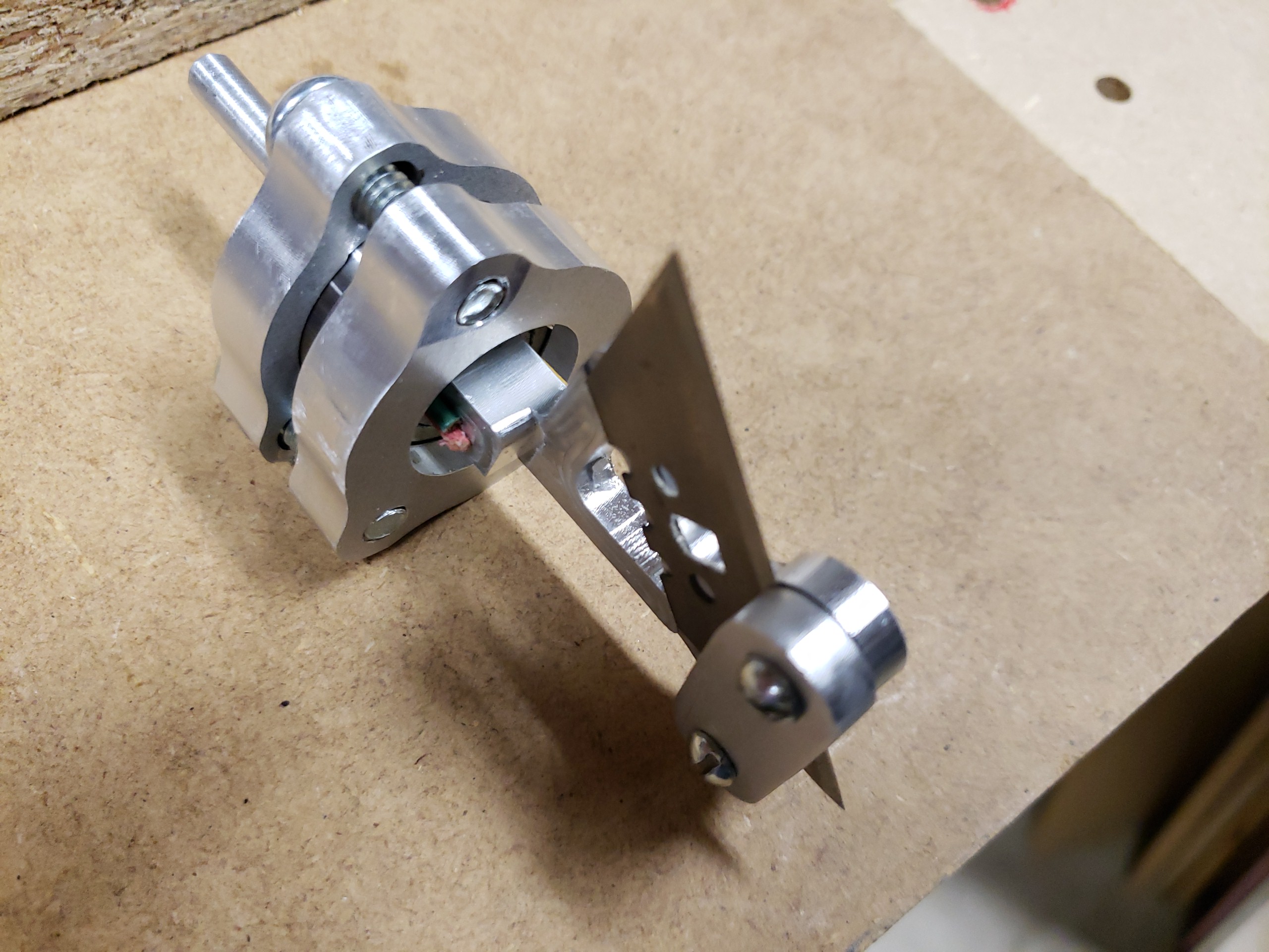
Jeff, it’s not clear from my pictures, but the only thing that turns is the frame, the piece with the blade attached. It comes out square and slightly too big to fit in the 0.500" bore of the bearings. A little bit of gentle filing on the corners and a lot of try-file-try and it will slide in.
The two bearing holders bolt together sandwiching the bearings between them. The top of the frame is just long enough to go through both bearings. The mounting shaft attaches to the top bearing holder and mounts in the router. Everything but the frame remains stationary, and the router is obviously off.The hole in the original design was for a 1/2" router. I made the hole in the top bearing plate 0.250".
The long section of the shaft is 1-1/2" to fit all the way into the router chuck. The short section is 0.175" to match the thickness of the bearing holder. I epoxied the shaft onto the bearing holder because there’s not enough meat to thread. The shoulder butts all the way up t the collett nut and is about 0.750 wide to provide as much surface area for the epoxy as possible.
I turned the shaft on a lathe, but one made out of a piece of 1/4" threaded rod with a nut screwed on would work as well. It would actually provide more surface area for the epoxy and would be faster.
When you get ready to try it I can send you better pictures and description. It’s a blast to watch it work, and it was cool to see what an easy time the LongMill had with aluminum. Watch some of Winston Moy’s YouTube videos - Anything the Shapeoko can do the LongMIll can do.
Jeff, if you’re still interested in trying aluminum I’ve been working on a new project - a Z height probe for mapping the elevation of stock so you can make Z zero change across an uneven surface. I keep trying to use boards that are cupped or bent and some are so thin to start with that surfacing would make them too thin. It would also work for milling curved surfaces.
Right now UGS doesn’t support auto-leveling because it can’t store variables, but there is other software out there that works with an Uno and UGS. So I designed a very simple tool that will mount in the router, connect to the LongBoard, and provide a way to map surfaces. The parts are made from 3’8" long pieces of 3/4"D aluminum rod. I have the F360 toolpaths complete and I should have the prototype done in a couple days.
That sounds very interesting! I just ordered a small piece of aluminum a few minutes ago so I could try my hand at milling it. I’ve been distracted trying to cut those Tiki Masks for the back yard, but I’m down the rabbit hole on getting the lovely STL models in to a flat image so I can bring them in to Fusion and play with the depths. They cut fine as they were but I want a large difference between the height of various elements so I need to edit them.
On the upside, I did get my dust collection working well with the shoe, so in a better place to try the aluminum milling when the stock arrives. Will keep an eye out for more on your Z height adjustment goodness.
Jeff, either MeshLab or Mesh Mixer, maybe both, lets you scale a graphic in non-uniform ways, so you can expand in the z direction only. If you can, edit someplace other than Fusion - SLOW.
What did you do to the ventilation? My shoe works well, but I’d like to make it easier to adjust and get it out of the way. It also reduces the X travel by a couple inches.
@BillKorn I’ll be following your progress on your surface follower, Bill. I’ve read a thread on the UGS google group about some guys looking at continuing the development of such a thing in UGS. The module is there, I understand, but it was never completed. I have some projects in mind to carve onto domed surfaces, but I don’t have any concept at all of how to program such a thing.
I’ll give MeshMixer another try. I was using it to try and clean up the model to make it easier for Fusion to digest, but it didn’t occur to me to try and solve my issue there. I might try Blender too. So many complex packages to try and learn. I just want to make stuff!
Thanks Hansi, but the credit goes to Brian, the guy who designed it. I’ve cut a number of thin materials with it. I have an architect friend who builds models of his designs to show clients, and I’ve used it to cut the hundreds of parts for two of his models. Apparently it’s way easier than the way he used to do it.
@BillKorn Bill: I think that I’ll buy the plans, but can you please tell me how the round spindle is attached to the bearing mount? I understand that it does not turn. Do you glue it in?
@BillKorn Bill: Me again. I bought the plans last night. Did you use the dxf to start your process? I just quickly played with it last night, but when I run the toolpaths in VCarvePro, the parts do not look like yours. I’ll spend more time with it today, and may find the answer myself, but being lazy, I thought that I would impose on you first.
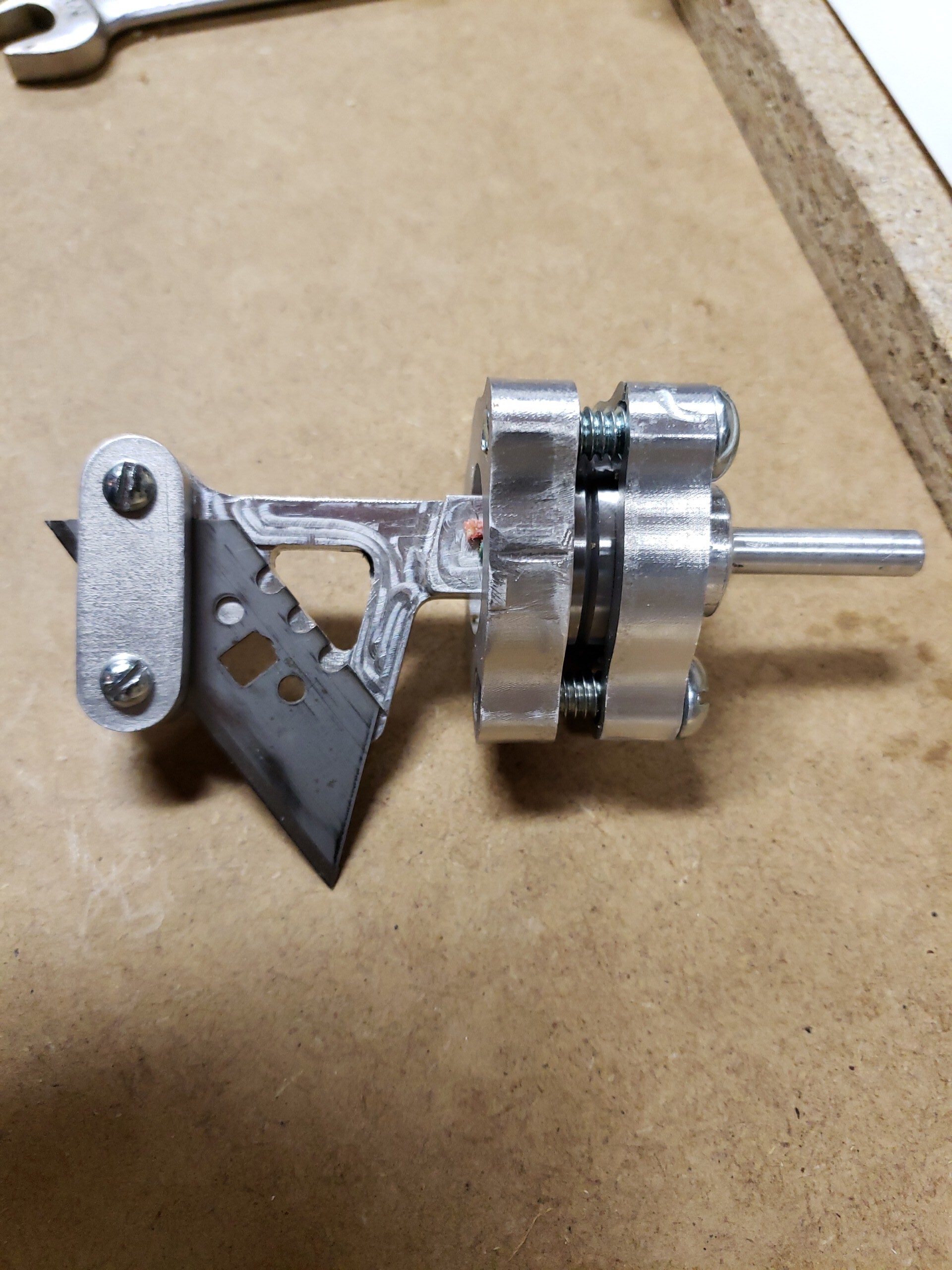
The original design was for a shaft press fitted into a 1/2" hole in the top plate. I reduced it to 1/4". In this pic the short shaft fits into this hole and is just short of touching the top of the frame. The long shaft goes in the router.
Since the shaft is only 1/4" and the top of the plate is pretty thin I was worried that the side forces would pull out a press fit so I epoxied it in place.
Now that I’ve run a bunch of parts I see that the whole thing may be a little over-designed for small routers. If you looked at the videos you can see that the whole knife turns with the blade instead of the frame turning in the bearing plates. It looks like the router shaft is easier to turn than the knife in the bearings. Maybe my alignment is a little off, but I’m thinking that the bearings in the router are significantly better and easier to turn than the bearings in the knife.
I started with the .stp file in F360 although I think the .STL would work as well. I can send you the section elevations of the parts if it will help. I guess I could actually send you the F360 files since you bought the plans.
BTW, one thing to check in your design. The little nub on the frame where the blade mounts is there to keep the blade from swiveling during cutting. It’s in the wrong place for the blades I use so I had to move it. Easy in F360.
@BillKorn Bill: What took you so long. I just got all the toolpaths to work. I started with the dxf, which was a bit confusing, as he included all kinds of diagrams that were not necessary. Also, there were a ton of open vectors that VCarvePro didn’t like. I have all the toolpaths done now. My plan is just to cut them out in some thin mdf to see how they look. I don’t have any aluminum right now anyway. I’ll keep in mind the issue of the blade nub.
With my local bearing guy closed, I won’t be playing with this for a while, expect.
I’m thinking that, maybe, when I get to try it, I’ll tape down the spindle lock on the router. What say you?
Thanks much for the tips.


 I just got all the toolpaths to work. I started with the dxf, which was a bit confusing, as he included all kinds of diagrams that were not necessary. Also, there were a ton of open vectors that VCarvePro didn’t like. I have all the toolpaths done now. My plan is just to cut them out in some thin mdf to see how they look. I don’t have any aluminum right now anyway. I’ll keep in mind the issue of the blade nub.