Has anyone ever wanted to enter a specific coordinate for X,Y and Z positions? Is there a way to do that in gSender?
I just tab across with the arrows until I get there. I am not sure that there is a GoTo function.
1 Like
You can click on the Axis Numbers and enter a value, I use it all the time for through cuts for example, say I have 1/2" stock I’m cutting through I set the bit to just kiss the bed and enter -1/2" for Z, that’s assuming I used the surface of the stock as start point in VCarve.
EDIT: I think maybe I misinterpreted your question? I was thinking of the zeroing thing because I do it, not jogging to a specific coordinate if that’s what you were asking.
2 Likes
I’m always entering how far I want the router to move in the XY and Z. for example, 10.675" in XY then I click the directional arrow I want it to go in.
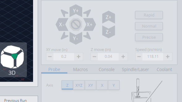
2 Likes
Michael, I am trying to understand the full process of what you are doing here as it seems to be a better way than I am using (ie zero off the top and then cut down to how much you measure your workpiece to be)
Please can you lay it out in more detail for me .
Thanks
2 Likes
@_Michael I do what you do, Michael. I have macros for pretty much all of my stock material thicknesses and they are each mapped to a keyboard shortcut. That means that I cut through the material even if the thickness is off a bit and I don’t muck up my spoil board.
1 Like
You hit the nail square on the head sir. I was talking about jogging, however this is good info. Particularly when I’m using the center of the piece to zero X and Y. I’m doing several returns to make new cuts after some finishing work. I need to go back and seem to have lost my coordinates due to running more than one project at a time on the same bed. Dare I say that I messed it up! Anyway, I just need to get back to the exact same place to make a new cut that needs to be aligned with previous cuts.
Thank you ![]() for the help sir. I’m going to try this.
for the help sir. I’m going to try this.
@GregM, I should learn how to do this.
Thank you Swinly,
I’m going to take a look at that. It sounds too easy, ![]()
![]()
![]()
Hey GregM,
As I understand it, by setting the bit to the bed and entering 1/2”, for the 1/2” stock, he is effectively setting the Z Zero where he needs it 1/2” above the spoil-board. If the stock is exactly 1/2” he’s good to go and reduces the damage to his spoil board. If his stock is a hair under 1/2”, he’s still saving the spoil board and because he’s cutting all the way through, his stock is also safe.
1 Like
Swinly, you’re a genius. This is exactly what I needed.
![]() thank you
thank you
@GregM, @Parkey pretty much summed it up, It basically makes errors in board thickness amount to cutting air on the top side instead of cutting spoil board on the bottom side.
If you keep your cad/cam like your used to, with zero on top of the project and you know the project height then the bed is zero - project height. So you can set X/Y the way you normally do but instead of setting the surface of the project to zero you set the spoil board to -project height. It’s important to not miss the minus sine in there. This has resulting in me rarely damaging my spoil board. I picked it up on this forum and to me it’s a much better than “just cut a little more than project thickness” and plan to cut into the spoil board. I laser burned a grid in my spoil board and it is still usable after many projects.
EDIT: Credit where it’s well deserved I learned this by way of @gwilki from this video.
2 Likes
@ _Michael,
I also laser burned my spoil board and even though I haven’t done many projects yet, my spoiled board has lots of first timers, but it’s still pretty usable since I’ve been practicing on getting the Z cut through’s measured up. This is going to rescue it and save me a ton of time.
I’m grateful sir. ![]()
2 Likes
Perfect…
Thank you !
Time.for.a new spoiler board now .
1 Like
Another thought on this. If I’m surfacing my piece, I could use this method to surface it to a specific thickness. A great technique to use for something that might need to be inserted into the groove of a frame or a base plate???
Would you agree?
Agreed.
I have actually transitioned to doing almost all of my work with the zero set to the spoil board in VCarve now. It takes a little more work setting up the tool paths but then all my work is just ‘touched of the spoil board’ for Z.
For example lets say I had some 1/2" nominal stock I was going to V-carve and cut out a shape, a basic plaque or sign. I work in mm so 1/2" is ~13mm.
- The first thing I would do is surface it to 12 mm thick, so a 1mm pocket over the whole work area.
- Then the VCarve start depth is 1 and if you wanted a flat depth of 2mm from there that would be 3mm. That’s where it takes more thought in CAD IMHO.
- Lastly the profile cut would start at 1 and cut a depth of 12.
With that way of working in VCarve all my jobs become set XY to lower left or center of job, then set Z to zero with the bit just touching the spoil board. You get a nice V-carve becase the carve surface was just surfaced to 12mm thick and the V-carve set up accordingly.
It seemed weird to work that for a couple of jobs but now it looks natural and all of my work takes place in +Z, that’s above the grid ‘floor’ in gSender which is kinda neat. If I see anything below zero I know I’ve gotten something wrong right of the bat.
1 Like
That makes total sense to me.