I’m getting more into Fusion 360, and more comfortable with 3D modelling, so I thought I would try out a more complicated 3D carve (since so far I have been doing essentially 2D).
I decided to try carving a shift knob - not the most complicated shape, but something I could improve on and try some prototypes out of scrap wood before using better stock.
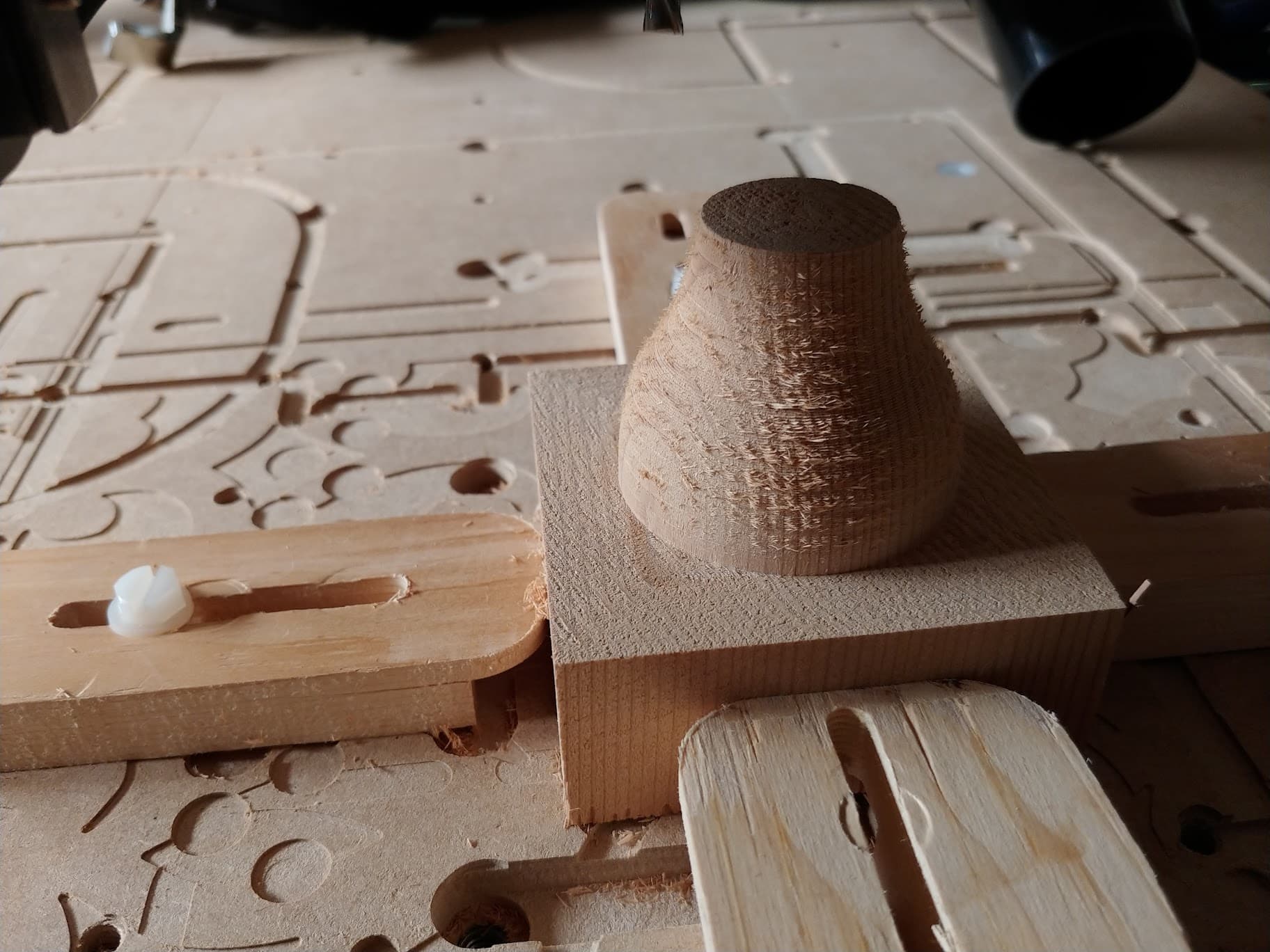
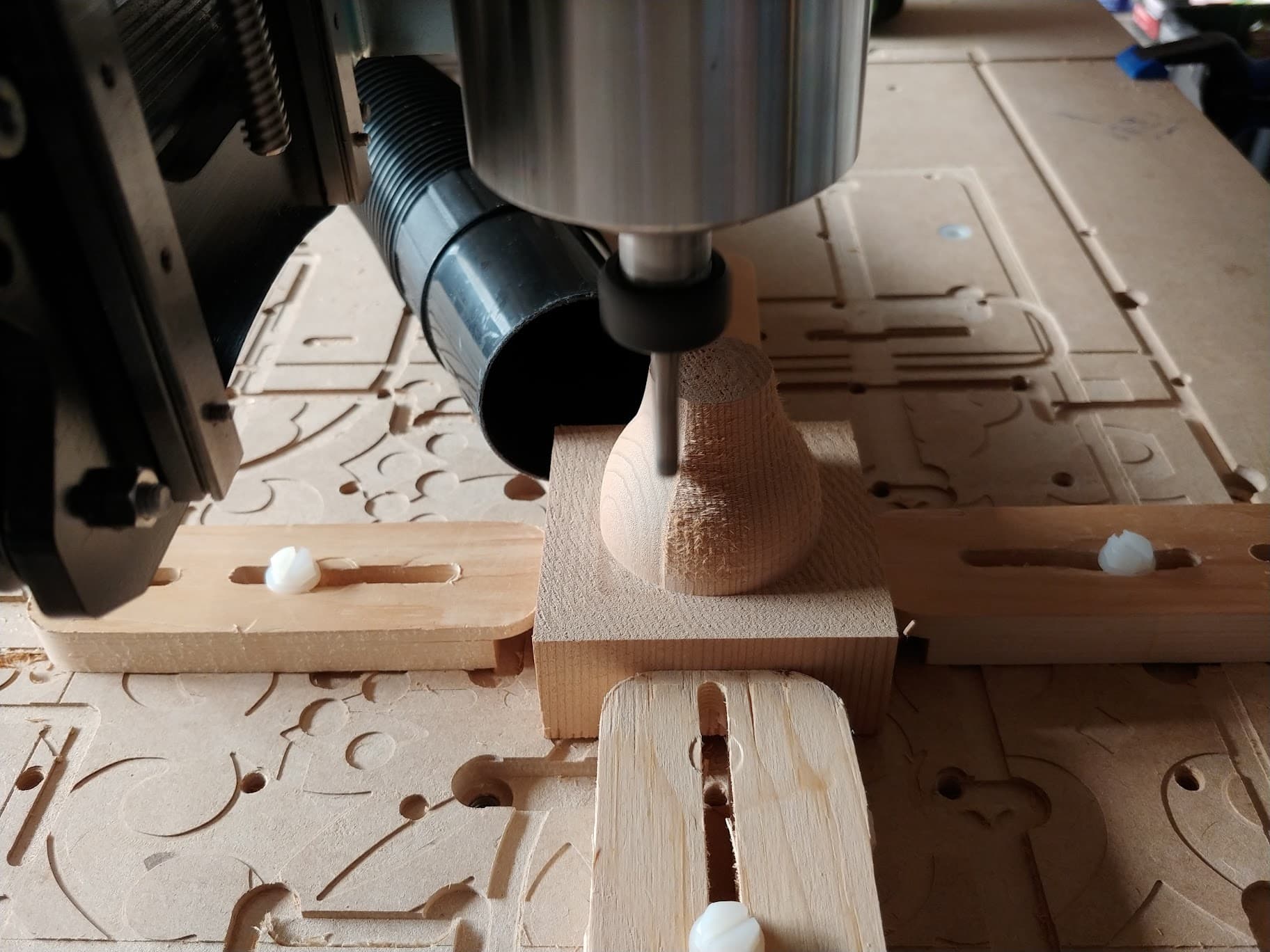
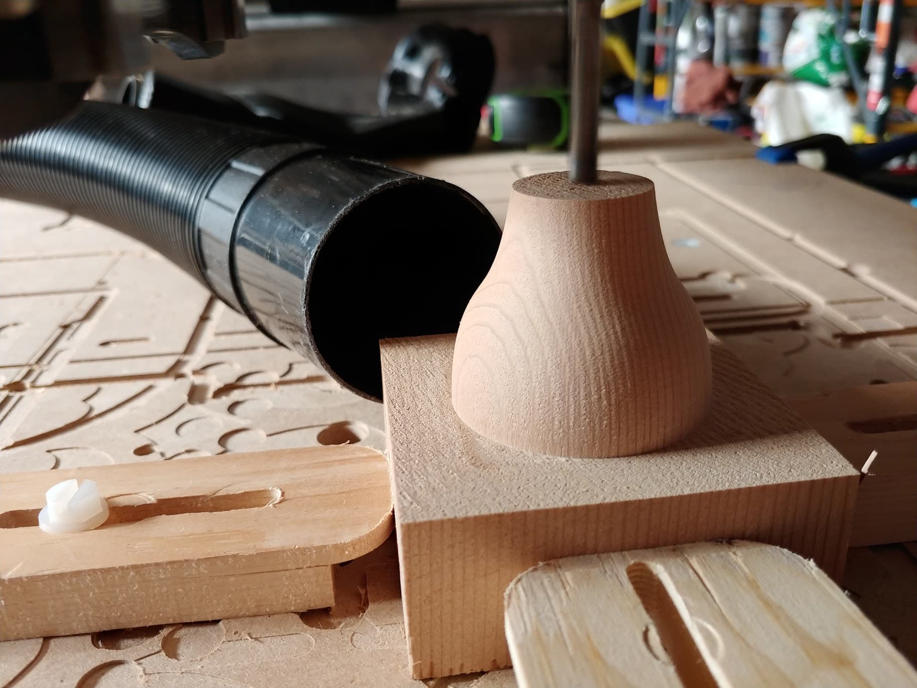
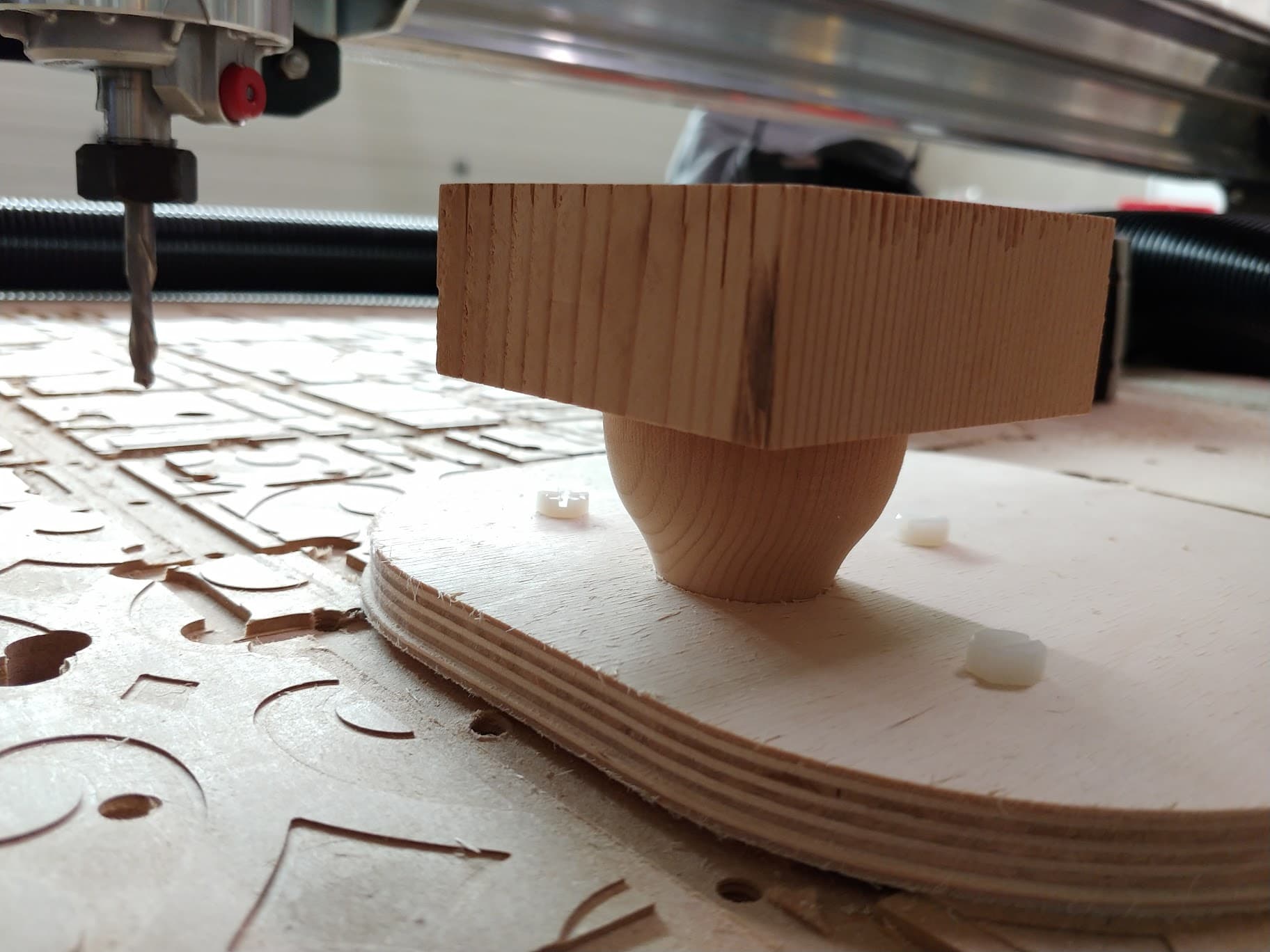
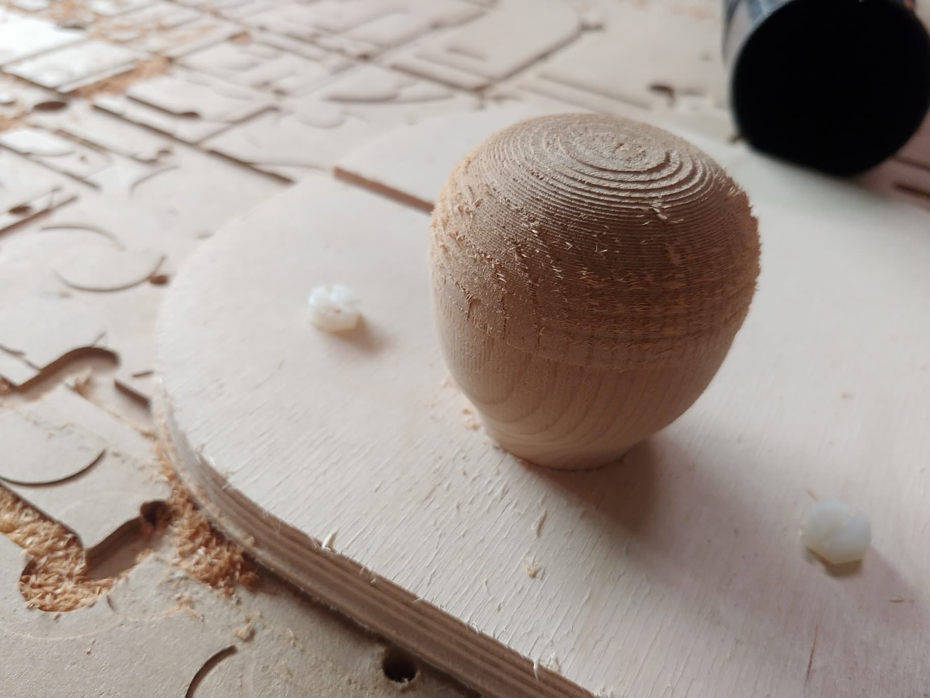
The results at the half way point look pretty good. Here is the roughed stock (using Fusion 360 3D adaptive and a 1/4 inch downcut endmill):
So I’m loving the results so far - but now it’s time to cut the other side.
I have some ideas for work holding and centering - mainly to bore a locating hole in the top, and a locating hole in a fixture plate, and thread them both (being sure that both are bored to a known XY zero).
Any thoughts for making sure it well secured? The last thing I need is for it to unscrew itself while it’s running. I thought about milling flats onto the base, but that seems like it would ruin the look. I think I would like to make a few of these - so solving repeatable work holding would be a handy thing.
Right now I am working on a tray to hold billiard balls. Could you give a bit more detail on the tool paths you used? I have the tray modelled but cannot figure out tool paths.
As for work holding, maybe leave a square projection on the base ~ 1 cm thick. With a centering pin for position you could then clamp the square projection. Then saw it off when the top is done.
Thank you @Ryecon - keep us informed of your billiard tray, I’m sure we would all love to see it.
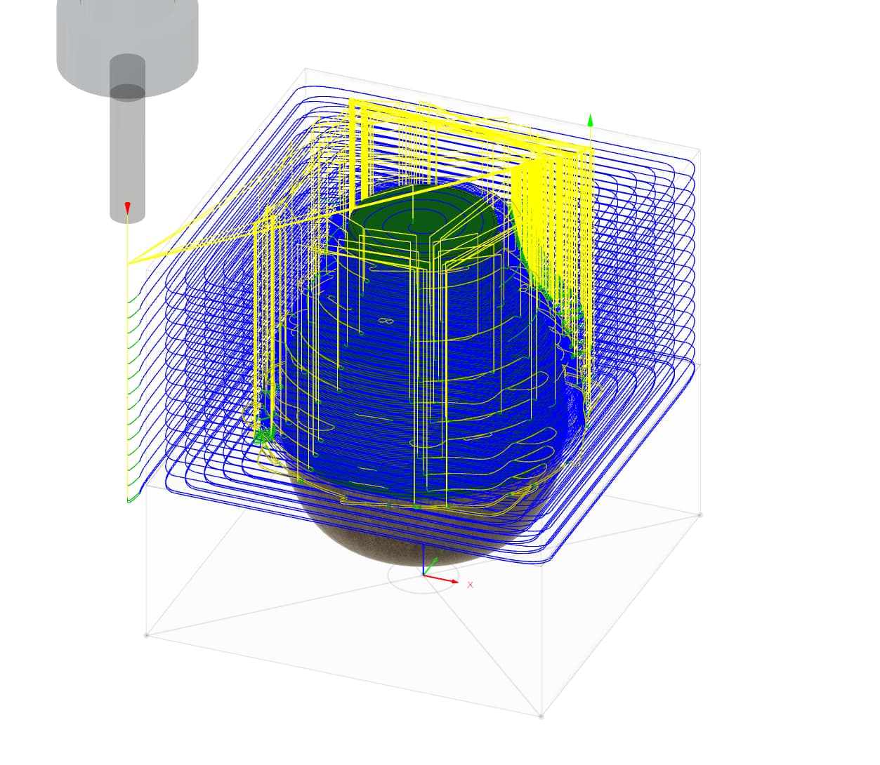
For the toolpaths used, first pass was 3D adaptive clearing with a 1/4 inch down cut endmill, with a cutting feedrate of 80 inches per minute, plunge at 20 inches per minute. “Optimal load” was 0.1 inches (I believe that is how much of the cutter gets engaged in the work). Stock to leave of 0.02 inches radially, and 0 axially.
Second pass was Radial, selecting the center point to be the center of the knob’s base. Same tool and feed rates, no stock to leave.
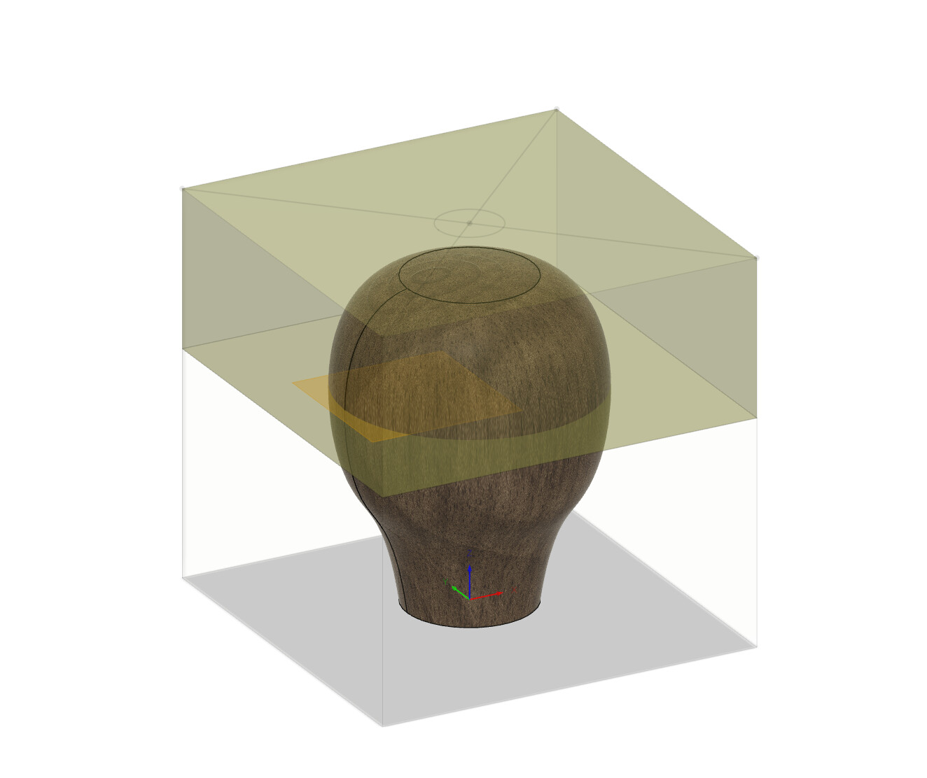
To cut the two sides of the knob, the stock is modelled in two pieces, with the dividing line being the widest point of the knob (so that the cutter can reach both sides).
The overall stock height is 3 inches - which leaves just under 1/5 inch to drill a hole in the bottom as pictured and use it as an alignment / hold down for the first setup.
For machining the other side, I have a second setup with the part oriented the other way around, and a repeat of the same two operations. If that goes well, I will see about carving a logo or shift pattern in the top of the knob when it’s done (without removing it from the machine, so that I don’t lose my zero).
I have also toyed with the idea of cutting a “nest” to cradle the part out of scrap, for work holding if I want to put the part back in the machine accurately for any further cutting. Fusion would make it easy using the cut operation.
@elbarsal Looking very fine, Ed. In terms of holding it down for the other side, I think that @Ryecon/ Andrew’s idea is a good one. If it’s too late in this project to do that, I suggest that you use a waste block. Wood turners frequently use waste blocks to hold their bowls, etc. They are nothing more than a block of wood that will be “wasted” when the project is done. The bowl can be attached to the waste block with glue, double sided tape, mechanical fasteners, etc. The waste block is held onto the lathe and when the bowl is finished, it is removed/cut off.
You could attach the knob to a waste block, then hold the waste block down to the spoil board with clamps, tape, etc. If you choose to hold the knob to the waste block with a screw up through the centre of the knob, be sure to set the CAM software to carve in the direction that tightens the screw.
Yeah I am thinking of something like you say, screwing up into the knob to hold it. I think Fusion even defaults to clockwise (tightening) adaptive clearing. I might have to remove my spoil board to get a bit of height back to do so, since my machine isn’t up on feet (which puts the top of the stock at 3.75 inches above the bed of the machine).
I will post my progress - I’d like to get this one finished, even the prototype looks so good so far! My only real quirk now is the car the final knob is going on (Triumph Spitfire) takes a 5/16 UNF thread, and all the inserts I find are 5/16 UNC - but that can be dealt with - maybe with epoxy reinforcing and just tapping it directly.
@elbarsal In my previous life, I rallied spitfires, mgbs, mgas, even mini coopers - in short anything that I could get my hands on. I think that you will find that if you tap the wood directly, you will be fine. FWIW, when I tap wood, I run the tap, then flood the threads with thin CA. Let it dry thoroughly without accelerator, then run the tap again. You will end up with very hard threads.
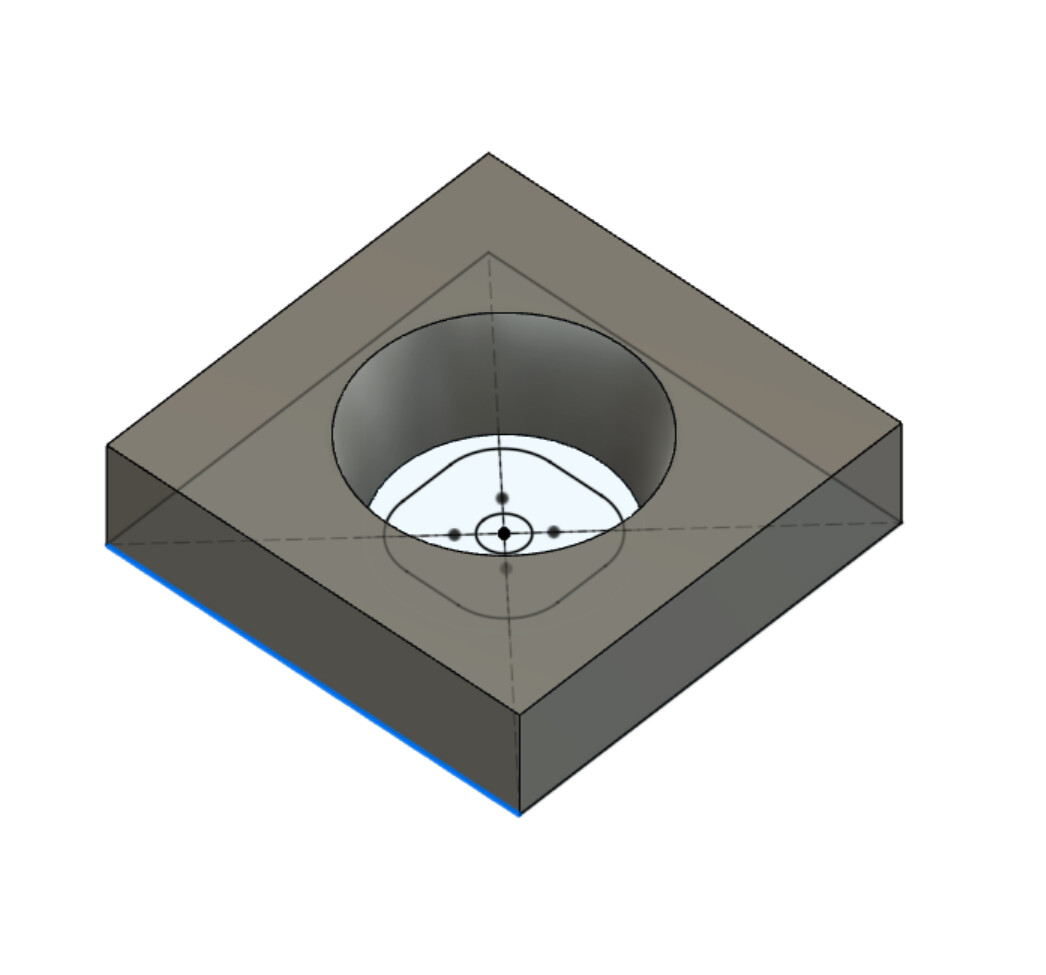
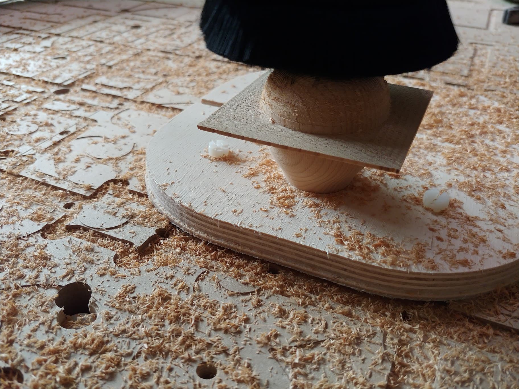
So the scrap wood I am experimenting with didn’t take a thread really well, and secured to a waste block, it exceeded the available Z space for my current setup. Things were pretty precarious, too - so I decided to try milling a “nest” both to get some Z back, and to better secure the work.
Getting Fusion to generate the internal finishing pass was a pain (for @Ryecon I had to use “Contour”), but when I finally did, it really fit like a glove - pretty well press-fit. Between the nest and the so-so threading (I threaded it down into my waste board), it was surprisingly stable, and I gave it a shot.
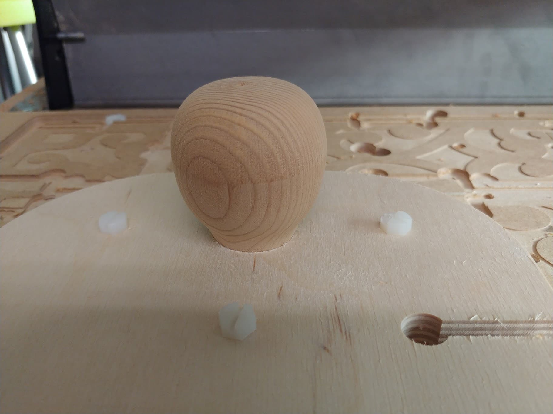
I think the results speak for themselves - I’m surprised at how nicely the top and bottom cuts mate (a key is that I cut the nest to the same XYZ zero as the final cuts on the knob.
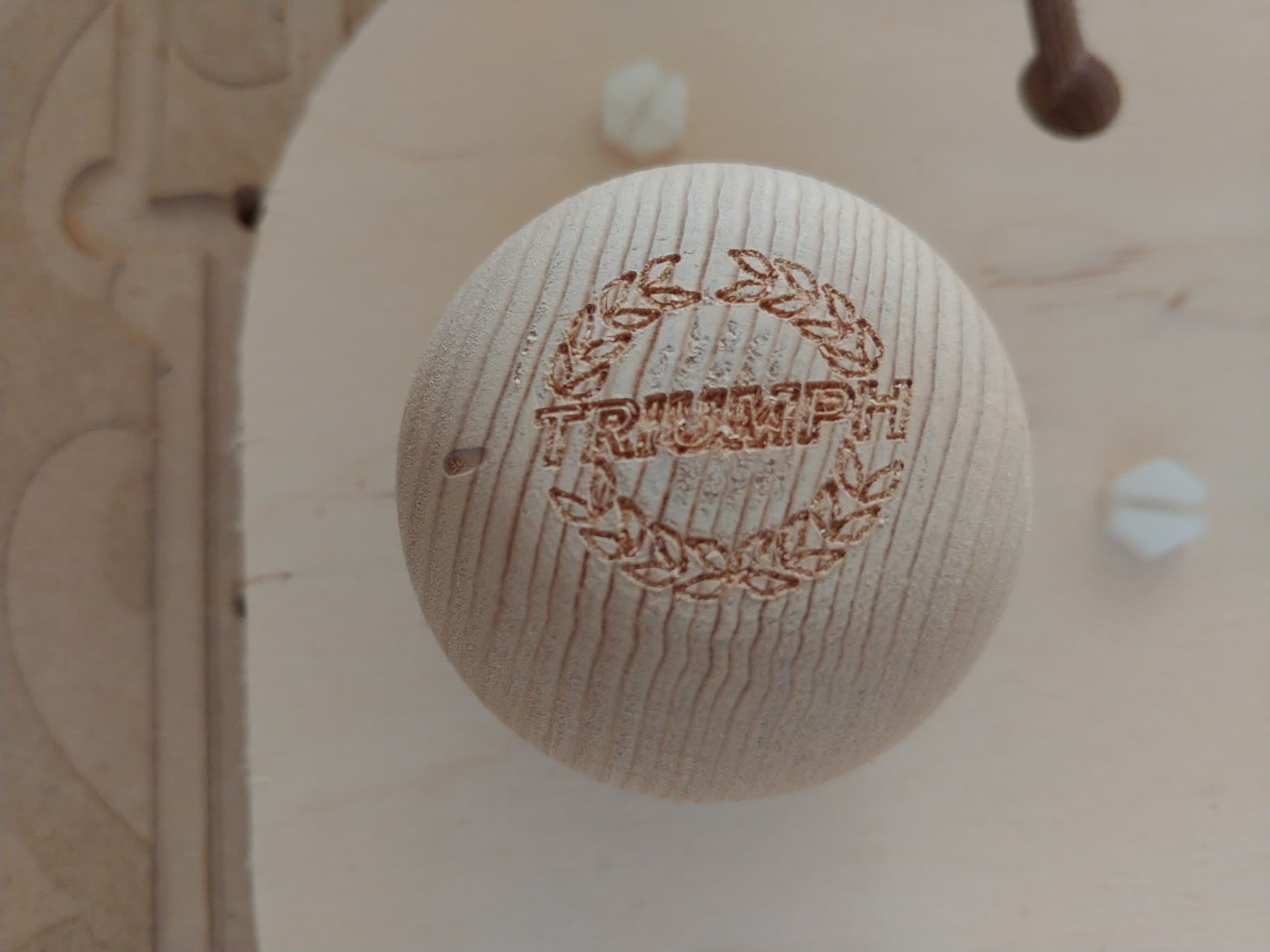
The close up shows the lettering well, but also the fact that this is softwood of unknown origin - still came out nicely though, especially after a light sanding. Going to hit it with some finish and see if I can get it to shine.
I have had two TR3’s, one TR4, one TR4a, one Spitfire, and one TR6, the beast! Must have been a glutten for punishment, they could sit in the garage and just break on their own!
Final shift knob post - found a suitable threaded insert that makes my prototype useful (still planning to do something in walnut, but this will work for now). Many layers of polyurethane later, it’s in service:
Mill it from both sides in the axial plane? This would avoid any mismatch of grain. You could make a simple flip jig or just have regular stock and flip and clamp it against an angle or index pins. It is a really lovely project, Ed. If it were mine, I think I would laser cut the text, which would leave it with a brown colour but it would be far more legible than it is now.
If you really could not do without the text engraved, I would probably opt to blacken it so that it stood out against the darker wood of Walnut. A highly polished surface would probably feel good in the hand as well as looking attractive. I love natural finishes and sand to around 3000 grit then finish with beeswax. It feels smooth and looks fantastic. Very inspirational work though.
I agree 100% on cutting the text with a laser, or at least darkening it in some way - as soon as I see Sienci lasers shipping, I’m going to place my order for one. I have a nice piece of walnut all set to go for my first non-prototype version. I’m hoping to refine the shape a bit (it ended up a bit chunky, going to narrow it a bit) and also hopefully work in some details that show off the fact that it is not lathe-cut that may also conveniently help with work holding.
I feel like I’m going to end up with a selection of shift knobs to suit my driving moods… this prototype in unknown reclaimed softwood, hopefully soon version 1.0 in walnut, and I’m also hoping to try out a laminated Baltic birch variant or two, where the ply is either stacked horizontally or vertically, showing off the layers. I will also experiment with finishes - including beeswax, that sounds fantastic.
Two sided milling is one sure way to eliminate machining marks. It is a technique I have seen used on chess pieces, even extending to four sided milling. If you were going to produce a few of these, you may find that creating your own flip jig may be the most economical means to repeat the project.
Interestingly, whenever I have tried to use any type of ply, from relatively cheap to ridiculously expensive, I have always found voids in the material despite being assured that there are none. I no longer try to use plywood of any description. I have a supplier of hardwood that can and does provide me maple and cherry as lumber from this selection…
I’m definitely going to look at two sided milling with a flip jig. Among the design thoughts I have had is a separately inlaid shift pattern / logo disc - which definitely simplifies the top end of the work.
Those are some fantastic looking woods… we have a specialty supplier near us I should check out as well. A good friend also recently took down and milled a big cherry tree from his farm… it will take time to dry, but I know he is keeping pieces aside for me.
I had great luck with some Baltic birch I was using so far - and a pile of perfectly sized scraps that I can play with. I know it’s a dice roll to have no voids, but it’s worth a shot. I find myself looking at all types of materials (and material scraps) so differently now.
A poor man’s flip jig is to fix two pieces of material (1 x endstop and 1 x side stop) to your Spoilboard/Baseboard. Assemble them at 90 degrees to each other. If you then create a workpiece with even sides, you can just turn it over and re-clamp it against the right angle formed by your newly affixed end and sidestops. My own recent piece of 3D milling in maple was based upon an exact 170 x 170 x 22 workpiece. It should be trivial to mill to half the depth to 11, then turn the workpiece in its longitudinal axis and mill the second half. I will give it a try, after my project in metal is off the baseboard. It will require tabs to be placed so that the piece will not ruin any cutters as it is removed from the base material from which it is machined.
Inlays are nice and can be an exercise in frustration. An inlay would certainly add to the high quality feel of your custom made shift knobs. I used a fair bit of American cherry in recent times. It is a hardwood but I find it soft to machine and it creates a lot of sawdust. It is very easy to overdo machine sanding on a belt sander. You may find this wood hardness chart helpful.
Just to kibbitz, I’ll throw in here that another way to do 2-sided jobs is to use locator pins. I do a lot of two sided milling - pretty much every picture frame I do and the chess pieces that I have done. I simply mill 1/4" holes in the waste area of the piece, then mill their mirror in the spoil board. When the piece is ready to be flipped, I put 1/4" dowels in the spoil board holes and the material lines up precisely. This is no where near as sophisticated as @jepho method, obviously, but it works very well and is quite precise.
I like to use index pins too. In the bad old days, I used to place 4 stainless 1/4" dowel pins on a single workpiece. I figured that if two pins was good, four pins would be much better. When they were ever so slightly out, I could not flip the workpiece because it had too many index pins to align!
I will set up my baseboard for flipping work and post some images. The baseboard has M6 holes at 20mm centres in X and Y planes and only milling half the depth pf the workpiece makes that trivial to set just half of the workpiece to be milled. The right angled endstops permit the workpiece to be supported along its length and I clamp the workpiece into the angle.
I’ve had very good results keeping it simple. I’ve followed tutorials by Mark Lindsay and Vectric. VCarvePro make it very easy and one can create a two-sided job, create the index holes in one surface and simply copy them to the other surface. No measuring needed - a real plus for me and my old eyes.
For others reading this, and perhaps new to the idea,t he conventional wisdom for using this method is to place your holes non-concentrically. As an example, for my picture frames, I drill the holes on the back side in the waste material. Then, I cut the groove for the art work. That done, I remove the piece from the Mill, then drill the holes in the spoil board that I copied in the set up. I place the dowels in the spoil board holes, then flip the material and whack it down onto the dowels. (Forgive the technical term, there. ) Using this method, theoretically, the top side carving work must line up precisely with the back side carving. In practice, I have found this to be the case.
I have done chess pieces using this method and there is no visible seam between the front of the pieces and the back.
My apologies to you, @elbarsal Ed, if I’ve taken this a bit too far off topic.
Your work is excellent and I really look forward to your next versions.
@gwilki (Grant) no need to apologize, I’m loving the conversation! Personally I think that it’s great to have conversations around fixturing, multi-sided milling, tiling, etc - the more ideas, the better. I think a huge part of getting the most out of CNC is work holding - much like manual milling as well.
In a small way I did do a pin-based flip with this project - the center hole I drilled in the first setup became the locating feature for the second setup, as well as a hold down fastener.