Looking at giving it a shot. I’ve noticed some minor inaccuracies in deeper (Z axis) movements with regards to being square to the table base.
Scott
Looking at giving it a shot. I’ve noticed some minor inaccuracies in deeper (Z axis) movements with regards to being square to the table base.
Scott
I have not, but I’ve been thinking about it. I can see pretty clear ridges when I surface a board with a 1 inch end mill.
How would you do it? Shim the router mount somehow? I don’t see a way to adjust it otherwise.
Shimming the router mount (or shimming between the router and the mount) might work - not certain how solid the mount would be after that.
Mark Lindsay CNC has produced a excellent video entitled “Tramming the router on my Gatton CNC”
CNcnutz has good videos for this:
https://m.youtube.com/watch?v=D6pfIoyhgTc
https://m.youtube.com/watch?v=cKyfUaY5Ddg
From what I understood is that it’s important you tram the Z rails first so that they are square to the spoilboard before adjusting the router. Not sure how to do that on the Long mill…
This one is interesting for squaring the X and Y:
https://m.youtube.com/watch?v=lU0iZKajpoo
I’ve watched a number CNCnutz videos and they are really good. The problem I have with this video is he is trying to adjust a machine that need accuracy to 0.001" or less and he is using a carpenters square and a ruler! The process is great, the instruments not so much.
How out of tram are people finding their machines? The LongMill out of box should be close enough to tram that most people will not notice any out-of-tram issues.
I have not trammed my machine at all, and although I can see machining grooves, they cannot be felt by hand. I would recommend doing surfacing back and forth in the X axis as it provides the best results. Even a trammed machine will have some visible lines since the direction of the cut will look a little bit different too so it’s not a reason to be alarmed.
If your machine is out of trammed you will be able to feel significant grooves between each pass, especially if you are using a larger bit (larger bits will accentuate the tramming).
Here are some of my personal recommendations for adjusting your tram if you want to or find you are off significantly.
I want to preface this by saying that tramming involves making tiny tiny tweaks. If you’re not finding issues with day to day cutting, you may have diminishing returns on the adjustments. We use jigs during the assembly for the X and Z gantries to minimize any tramming issues.
If you are finding the router mount skewed, then you can remove the Z axis plate by removing the eight M3 screws that hold the Z axis plate to the linear guide blocks and the two M5s for the delrin block. I would recommend taking the whole plate off and loosening/tightening the M5 screws that hold the router mount to adjust the angle. Very minor tweaks can be made by just loosening/tightening the M3 screws that hold the Z axis plate.
If you are finding the X axis rail to be skewed, I would recommend loosening the M8 bolts on the shoulder brackets to adjust the angle.
I hope that helps.
I recently surfaced the waste board and found notable ridges left from the surfacing procedure for the Y axis. The X axis variance was virtually unnoticeable.
On my previous CNC machine, I took a piece of 1/8" aluminum rod, bent it to about 70 degrees, forming an L. I put the short end of the L into the collet and slowly lowered the Z axis and rotating the L. Eventually, the long part of the L touched the waste board. I then followed these steps:
The old CNC machine was a devil to adjust because there were no real adjustment points. You had to loosen the bolts on whatever you were adjusting and make adjustments by hand. Once fully adjusted, it worked very well until the next time I needed to adjust it (it was based on MDF for its structural parts and humidity had a tremendous effect on it, even when sealed and painted.
Once all this was done, I could tram the waste board and get no ridges that could be felt and once in a while would get no visible marks either.
Here’s a video on a pretty easy, no-tools approach to tramming. I think more than one set of data points is necessary to confirm you’re done, but I think this method will get you close. The real issue is finding the best places on the LongMill to make the adjustments on all 3 axes.
I am really glad I don’t own one of those machines. Those belts would be a pain.
For those who feel ridges after surfacing, did you also had problems with the x-axis placement in the gantries (had to hammer them in, angles didn’t align)? I feel ridges after surfacing at the far left and right sides (center is almost flat). Don’t have adequate measuring equipment to see how much.
In my mind, checking the tram, the accuracy of movement in each axis and making sure the X & Y axis are square to one another is all part of the initial machine setup and regular maintenance. If you’re only doing artistic work with the machine it’s less critical. If you’re using the machine to build other machines it’s absolutely critical.
The adjustments made were accomplished by loosening the router in the mount and moving it very slightly. Was very easy and while i did do the adjustments with a jig similar to the one in the video, it only took a total of 10 minutes.
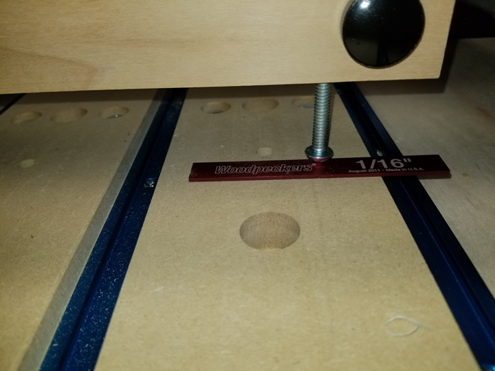
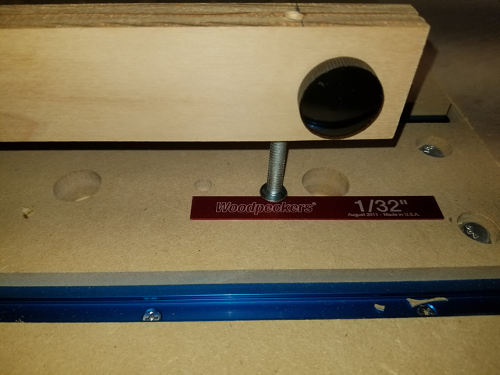
I checked the alignment of my router using the instructions in the video above. It seems I am out almost 1/16" along the X axis and almost 1/32" along the Y axis. I have been struggling with how to correct this as there seems to be no ability to make adjustments on the Long Mill and the tolerances are such that there is not enough slop to make any change just loosening and retightening bolts. The limiting factor is the bottom wheels that are mounted on fixed axles. This may sound crazy but it seems to me that it would be possible to make small rotational adjustments in both the X and Y axis if one or both of the bottom v-wheels were mounted using eccentric nuts like the top wheels. While this would make the mill much more adjustable the trade off would be that it would be harder to get it into a basic alignment which a majority of customers would probably be satisfied with. Before I start boring out the holes for the axles I am wondering if anyone has tried or even considered such a thing.
I was able to make adjustments just by loosening the router in the mount and moving it slightly. Only took a couple of minor tweeks to get it close enough. HTH’s,
Scott
I have. Basically I built a support table with framing and. MDF top. First, I ran the Y axis to the forward stops on both sides. Then I tacked down one side rail of the 30" longmill and moved the X gantry to the front, middle and back along the Y axis to screw down the opposite side rail suppotrs so they would be parallel. I initially tried to flatten the top waste board with a 1" cutter at 0.5mm depth, starting at the front left corner, but found the top to be more than 0.5mm off side to.side and front to back. So I used a piece of paper to find and zero my Z height at the front left corner and then used the same paper technique to probe each corner and the mid points along all sides and the middle, noting all the Z measurements. From this I then used thin cardboard and folder paper as shims under each support bracket as necessary. The final waste board flattening showed less than 0.2mm deviation in routing depth. Finally, I used a precission square to measure if the Z axis gantry was tilted off perpedicular relative to the newly flattened waste board, both in the Y and X axis’s, and it was not. I was prepared to add metal shims as necessary to the Z axis gantry if it was not perpedicular. Its a tedious process, but not difficult. Remember, there is only so much precision you can get with a wood sub structure and MDF top, especially with varying humidity effects, so perfection (less than a few thousandths off) is not possible, nor sustainable.
Tramming will be useless because I can tilt the router to the left or the right enough to make a significant left and right offset distance.
So… how do I stiffen or prevent the Z axis from tilting left or right especially when flat surfacing especially if surfacing using the X axis?
As far as I am concerned, the Z axis should not tilt or pivot at the centre of the lead screw rod.
The sliders can move up while the opposite side will move down and visa versa.
Then after if that can be fixed, how to tram the router on a Longmill and not a shapakeo as in the videos below?
@astro4000 Check the delrin wheels on the X gantry. If they are too loose, the router will tilt left and right. I’m assuming that your router mount is tight and your router clamp is, too.
The wheels are very tight. The slide guided allow it to pivot off the lead screw. How to tighten the vertical slides to prevent it to tilt on the Z gantry.
X and Y wheels are tight, nothing loose. It is the Z axis at the screw lead I am talking about. I can grab the router and physically tilt it either direction and watch the sliders move with the tilt.
Tramming the router would be fruitless if the router flops either way on the vertical guides.
The machine works fine, I just discovered this with the 22 mm surfacing bit while surfacing a 3 X 10 inch piece of wood and feel fine lines for each pass.