Hello!
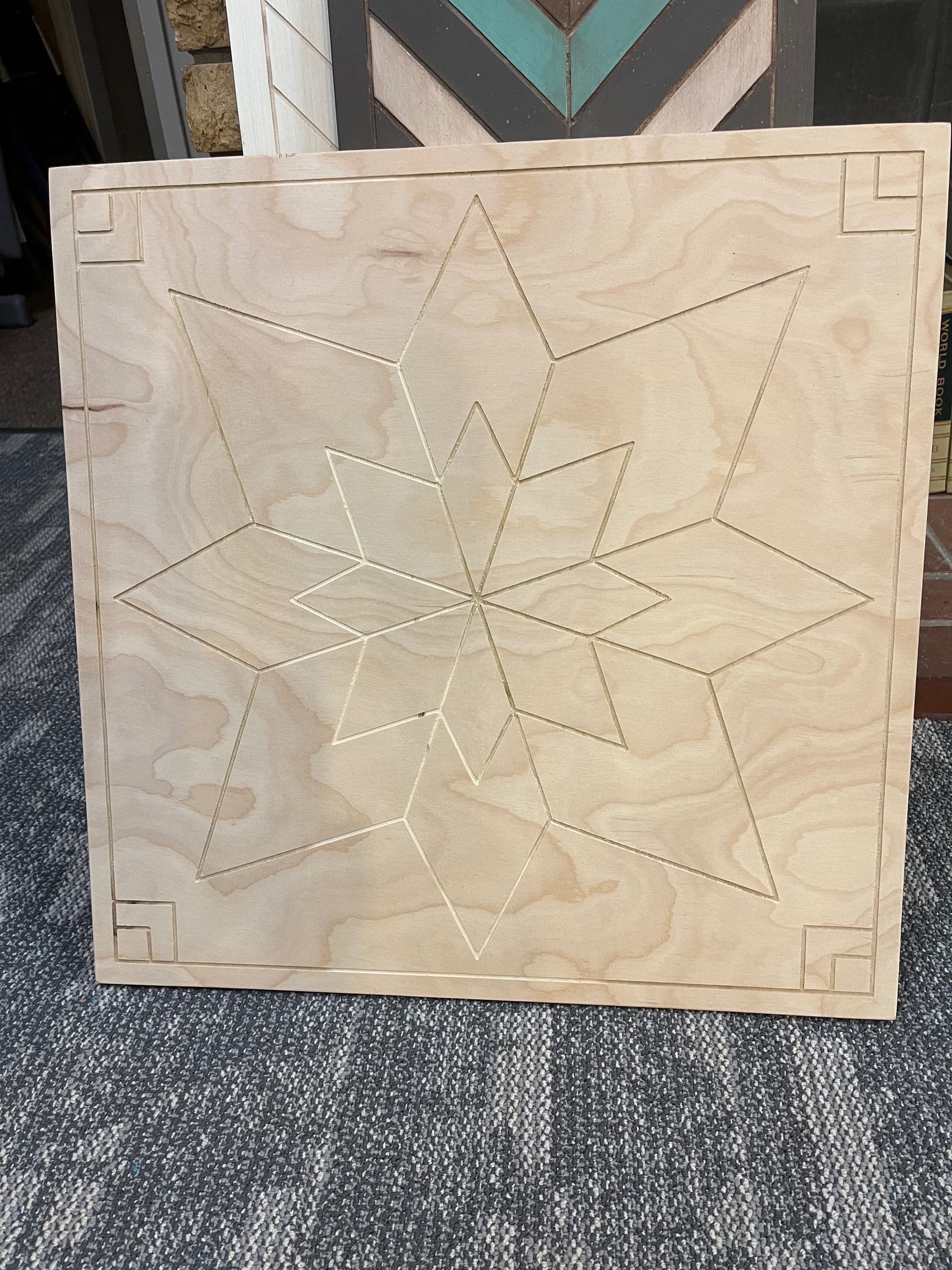
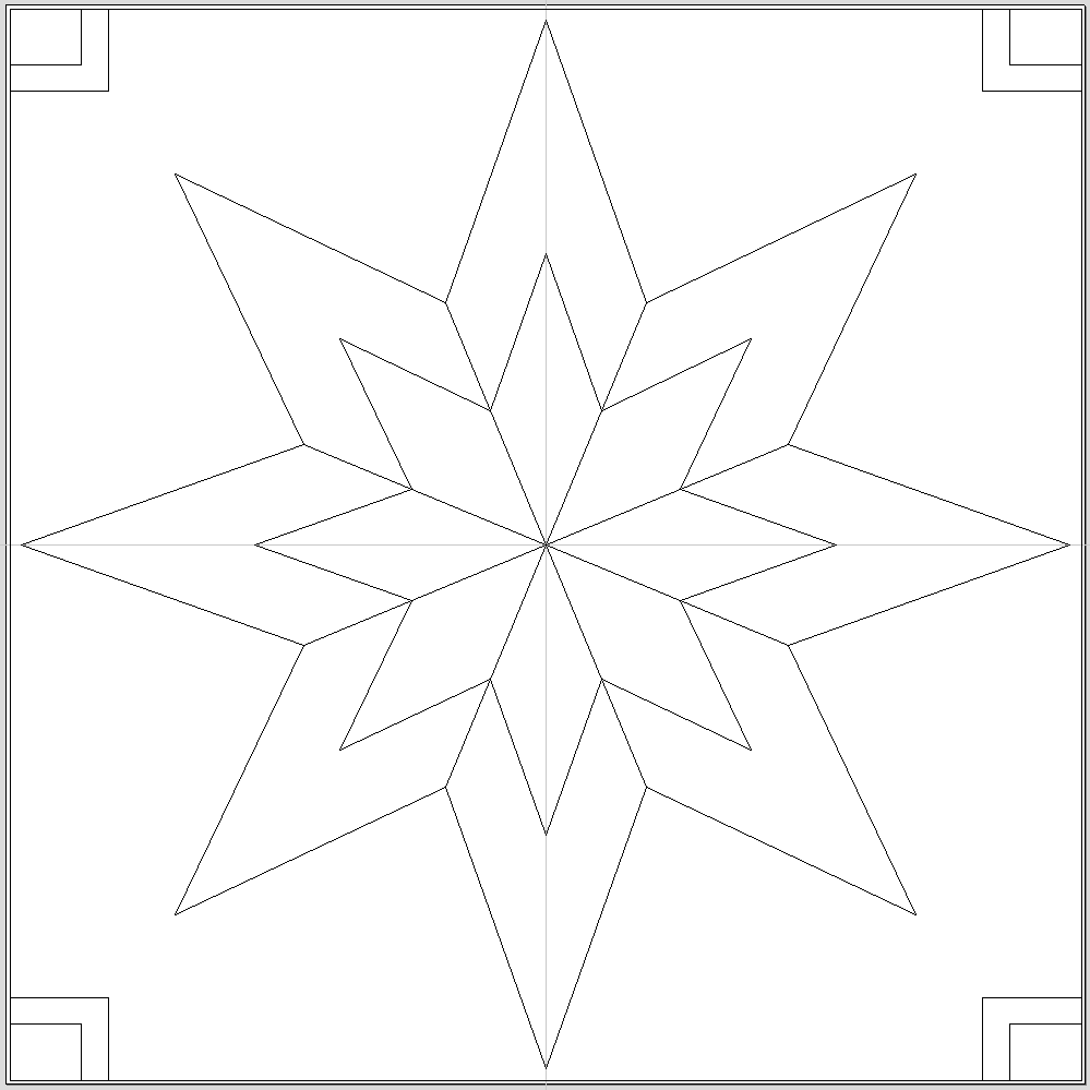
I could use a bit of assistance here. My customer wants this piece created that is 24"x24" out of 1/2" plywood so she can finish them with her students when she gets enough students. She is local and a delightful lady to work with. Her original is here
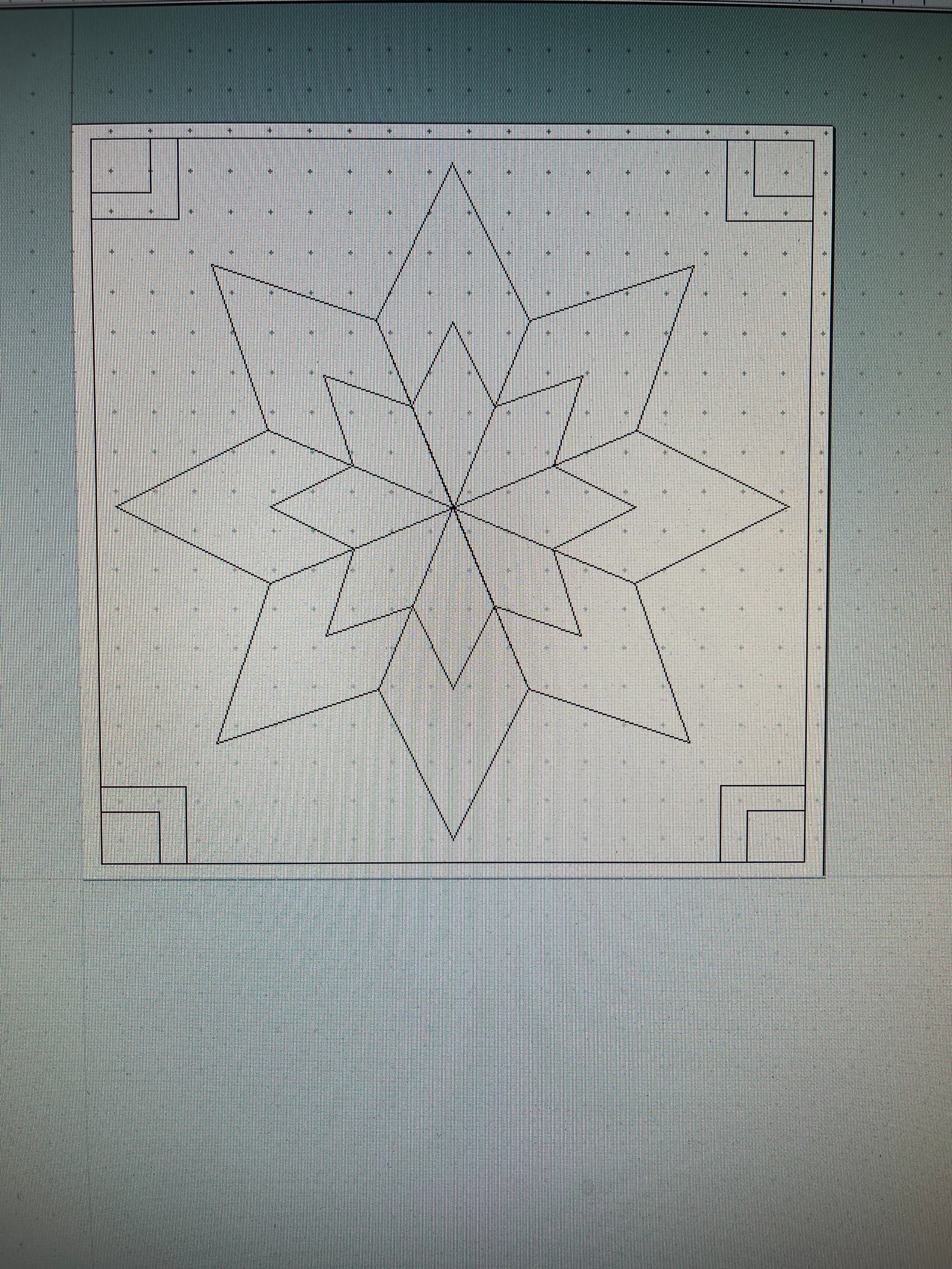
What type of tool path are trying to use? From the photo it looks like it could be done with the profile tool path, on the line with a small end mill or v-bit. The profile tool path should allow open vectors.
Edit: As far as closing the vectors if you have to do it, the open vectors could be closed with a line or lines on top of another line. For example two squares that touch can’t share a line for the common side, they each need their own to have closed vectors.
HI Michael, @_Michael . I am trying to use a small end mill to accomplish this. I will move the dots off of one another and see if that helps. I appreciate the response sir!
Jake
@Jake Hi Jake. I’m a little late to the party and @_Michael seems to have this in hand. However, it will help if you can post the.crv file. If you would prefer not to, no worries.
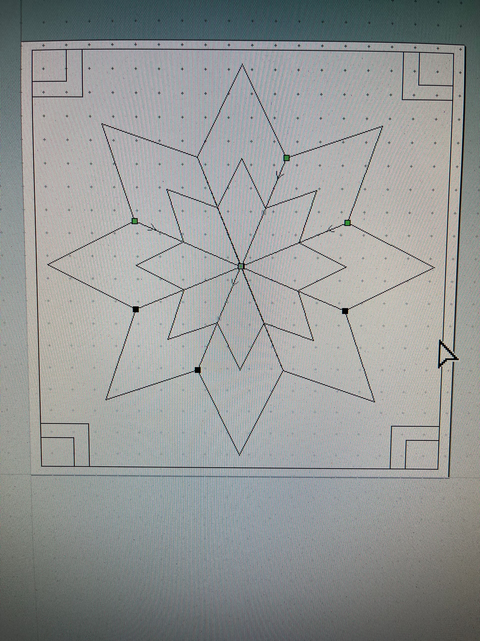
Hey Grant, @gwilki , I’ll post it when I get back home. It has me scratching my bald old head. I can move the green point around but it never groups it.
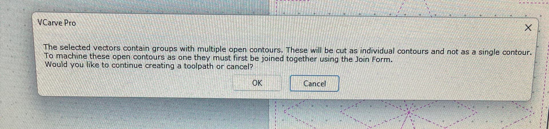
Just hit OK on that message, it will still cut the paths. “These will be cut as individual contours”, pretty sure you will get the result you want. Just hit OK and see what it looks like in the preview and GSender.
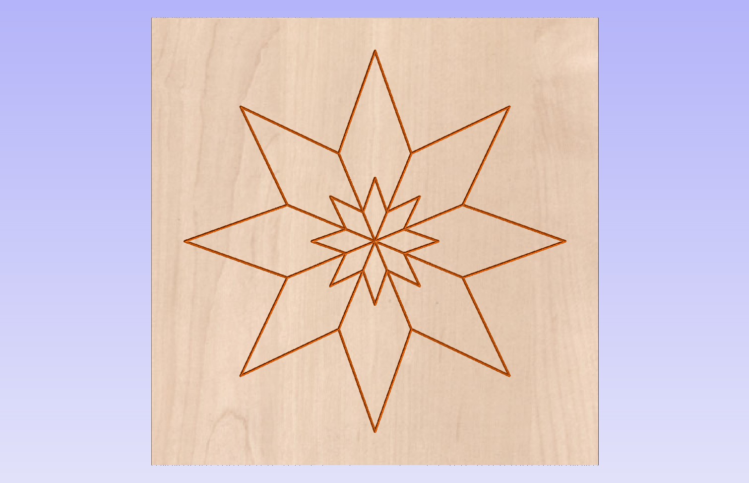
@Jake I didn’t pay too much attention to the ratio of the small “start” to the large one, but here is my attempt. It did not generate any error messages. FWIW
I was able to create a profile tool path without errors with the file you uploaded, not sure why I didn’t get the errors but here is the file with tool path. new 24x24 file.crv (53.5 KB)
Edit: I fixed a couple vectors that were off when I zoomed in, the upper right square and the lower right square as well as the center lines were a little off.
@Jake Like @_Michael, I was able to run your file using a profile toolpath on the lines without errors. However, if you zoom in close, you will see that your straight lines do not meet the inner corners of the outer star in a few places. The file still runs, but your results will not be what you are looking for. You can fix them in node editing, by selecting the end nodes and snapping them to the correct locations.
Thank you! First time attempting something from scratch. After dinner, I’ll go back out and attempt to run the file. I greatly appreciate the guidance gentlemen!
Jake
@_Michael Hey Sir,
Thank you so much! I take it my mistakes were having my lines off? It did run just fine when I ran the tool path you provided. I have it now, (thanks again) but want to learn what I did wrong. @gwilki mentioned “node editing” which I tried multiple times without success. Once again, thank you both for the assistance. I just want to get better at it.
Respectfully,
Jake
You are most welcome for any help I provided Sir. The thing is I don’t know why you were getting that message because I was able to create the tool path before I fixed any vectors. It was when I looked at the preview that I noticed some lines were off so I fixed them and redid the tool path.
As far as node editing goes, I didn’t use it, I just moved the squares and deleted the center lines and redrew them. I suppose I could have node edited instead but I didn’t.
@_Michael@gwilki For anyone on the fence regarding purchasing a LongMill CNC machine, this is proof of the power of the forum. This forum is exactly why I purchased my CNC from Sienci Labs.
I looked at most manufacturers of CNC units within this price point, and this forum was the most active and filled with good folks, willing to help a new guy. Just a quick testimonial on my personal experiences here. My hope is that someday, I will be able to give back as much as I receive from the people who frequent here.
@Jake I usually use the “Join Vectors” button and then the “Vector Validator” button before getting into node editing in the Vectric software. Usually less messing around that way at least for me.
Thanks @RickW I have another design to do, and for some reason, I struggle with it. It seems that either my hand isn’t steady enough or the mouse isn’t responsive enough. I have a large monitor I am designing with, so I can see the issues. I will give it a try. Appreciate the tip sir!
Jake