How Accurate is Accurate?

ATTENTION! Questions from a noob :grin:

After milling a few small squares (5") out I learned they were just slightly out of square. I milled a shallow 26x27 inch square in my wasteboard. That square is out 1.5 mm out from corner to corner. Should I attempt to get it closer than that or is it a waste of time?

Also, using UGS to jog the machine a given distance I found it’s also off. If I set the XY step size to 600 mm and jog the machine it comes up 1.5 mm short. At 800 mm it’s about 2 mm short. Is there a setting for that or it is what it is?

Thanks,
Bob

1 Like

@oxbowbob - Bob, I guess it depends on what you will be cutting and how accurate you need to be. It sounds to me like your XY is not quite square. Find two good diagonal points on your LongMill Y rails (corner to corner) and measure. If they are not the same length then it is not square. I think I measured mine about a dozen times during assembly before I anchored it. Again if you need square squares and round circles then square it up.

As for the jog distance it seems like your steps per MM/Inch are off. I didn’t have to adjust mine as it was good from the start. There are videos on youtube for calculating and setting this number. The $100, $101 and $102 are the parameters for the steps per MM. Issue the $$ console command and see what they are set to. Default values from Sienci are 200.00 for all three.

1 Like

@oxbowbob - Bob, just to clarify on the squaring. That’s diagonal corner to corner in case I wasn’t clear.

1 Like

@Heyward43 - Thank you for responding. I think since I’m so new to this and don’t know where it will take me it would be a good idea to start out as accurate as possible. I followed the youtube cncnutz & paw paw videos on squaring the machine with mixed results. That is when I decided to cut a square as a tell all. So once you determine that is does need to be moved how on earth do you get it screwed back down without it moving?? I have followed the mounting instructions, but it only gets me within that 1.5 mm. I have a feeling that putting the outside screws in is moving the rail, but getting them in there without it moving is a real trick.

I checked out adjusting the steps. It’s awesome you can do that, but it may currently be above my pay grade :grin: One thing at a time.

Thanks again!

If your machine moves smoothly along the full length of the Y axis then the two Y rails are parallel.
That is the most important thing.

The two Y rails, even though they parallel, may be slightly shifted front/back relative to one another. e.g. as this exaggerated drawing shows:

|         
|                  |
|                  |
|------------------|
|                  |
                   |

I would only remount the Y rails if they are not parallel.
But, if they are slightly shifted relative to each other (like in diagram above) then you can just spin one of the Y lead screws by hand to square the X.

1 Like

@mark Mark: With respect, the problem with leaving the Y rails “shifted”, and manually squaring the X gantry by hand, is that any time you hit the end stops, your X gantry is out of square again. If you have limit switches, I guess this would not be an issue. I don’t have limit switches and I do hit the end stops from time to time, so I set my Y rails equal to each other.

One user on here had an excellent idea, IMO. He mounted the rail feet to strips of MDF and had slots in those strips. He ran bolts through his table top into the slots. Then, he could adjust his gantries perfectly simply by moving the strips fore and aft. I with that I had thought of that. :grinning:

2 Likes

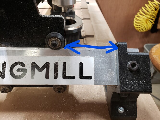
Just to stick my two cents back in … I did end up taking all the screws out and remounted the mill. My Y rails are as parallel as I believe I will ever be able to get them. If I take a 26x16 accurate square and hold it on the top part of the Y rail to the back part of the X it does NOT read square. As far as the rails being shifted … if I take a measurement from a given distance between the Y gantry and the front brackets I’m within a 64th. Is there a better way to measure this? I was able to calibrate the $100-$102 steps in mm’s to a point I’d call very accurate. I set up and cut a 22" square and corner to corner it was dead on.

I next set up to cut two small squares with about .5 radius on the corners from a piece of maple 1X stock. I cut an outside contour at 4.0119" with a .25 dc endmill bit. Even though the squares were cut close enough to call square, the size was not close enough to call accurate. They were both different sizes with measurements from 4.009-3.970". Does anyone have any thoughts on this?

Thank you!

@oxbowbob I’m not clear on what you mean by taking a measurement between the Y gantry and the front brackets. But, since you seem to be talking about how parallel your two Y gantries are, I would live with 1/64" variance. That’s just my opinion, though - worth nothing more than what you paid for it. :grinning:

Now, as for the X gantry not being square to the Z gantries, you don’t say how much it is out. I would run the X gantry back and forth, hitting the end stops front and back. Then, I would jog the X gantry to about half way in its travel. If the X gantry is not square to the Y gantries at that point, one of the Y gantries needs to be moved fore or aft. Then, the process must be done again. It’s a real pain, and if the amount that a Y gantry needs to be moved is very slight, you may well be in the same screw hole. I like the jason.shoes’ idea to mount the feet of the Y gantry on strips of wood, into which slotted holes are cut. Those strips are bolted to the table and can be shifted fore and aft to get things perfect.

All that said, if you are cutting 22" squares and they are dead on square, maybe you should leave well enough alone.

Since you can cut squares which are accurate (I’m assuming that the 22" square was not only dead on square, but also 22" on each side.), then you need to look at other variables to determine what went wrong with your smaller squares. I’ve not played at all with the .$100 to $102 settings, so I’m not competent to talk about how they may affect your dimension variance. However, if your 22" square was actually 22" on each side, I would say that your problem is not grbl related.

I would look to how you are cutting maple. How deep is each pass, what are your feeds and speeds. Even a 1/4" bit can be deflected by hard maple and hard maple grain if you are too aggressive. I have not seen one chip load chart that puts our Mill in the sweet spot using a Makita router and a 1/4" 2-flute bit, so it would seem that we need to choose feeds and speeds by the WAG method. Your squares vary by just over 1/32" - easily explained by bit or machine flex. You could verify that your delrin wheels on the X gantry are properly set. If they are not, the router can “nod” and mess things up.

I don’t know if any of this sermon will help, but it’s all that I can offer. I’m sure that there are others here more knowledgeable than me that may have other advice.

1 Like

@gwilki I could very well have explained it wrong. Here’s a picture of what I meant. I didn’t know how else to measure it.

I love the idea of the slotted strips. If I ever have an occasion to unbolt this thing you can bet they will be added on.

I don’t think any of that matters at all now. I cut another square 19.5"x19.5’. Dead nuts square corner to corner & dead nuts 19.5 around. It was cut in a piece of 5 mm plywood.

So on to cutting the maple. I “thought” my depth/feed rates were on the conservative side. Knowing very little & not being on the clock for any reason I hoped I was taking it slow. Depth is .060" & feed rate is 90. Thoughts?

I’m going to spend some time trying to get the wheels adjusted better and give it another go.

Thank you to everyone. You have all been a tremendous amount of help. Every time I read your answers it forces me to go learn what exactly you are talking about and another language :grin: Never in this lifetime did I think I’d be adjusting my grbls or flashing my Arduino!

@oxbowbob I don’t know where you are located, Bob, but in Canada, if you flash your arduino, you’ll be arrested. :grinning: And, we won’t even go into the consequences of adjusting your grbls in polite company.

Tks for the pics. I’m a bit slow, so I need all the help that I can get. If you are within 1/64" of an inch in that measurement, I would say it’s good. I think the only way you would get it tighter now would be to go with jason.shoes’ idea, since you would be in the same screw hole otherwise.

Since you are cutting nice squares in thin material, I’d say that you are dialed in. As for feeds and speeds in hard maple, you are more conservative than me. I run 120 inches per minute with the Makita on speed 3. That is not even close to the chip load shown in any chart that I’ve seen, but I get good results, so that’s my story and I’m sticking to it. Certainly, a pass depth of .06 is not aggressive, either. It is tough in hard wood, though. Grain can pull things of track by the amounts we are talking. It can’t hurt to slow down the feed and the speed and see what happens. As long as you are not burning the wood and/or overheating the bit, slow can be your friend.

2 Likes

@oxbowbob - I’m not sure if this would be a benefit or not. If anyone else has perfected this please chime in. I try to do a last pass of .05 or .1 to finish the cut depending on hardness. Since @gwilki stated correctly there can be a little deflection depending on wood type, speed and DOC. What last pass does is cut a very fine line with little or no deflection since you are using just the edge of the bit. I have not tested this other than to measure results and so far it works for me.

1 Like

@gwilki I’m in the middle of southern New Jersey, 40 miles from the Atlantic City casinos.

@Heyward43 In this case I don’t think that will work unless I started oversized as they are already undersized. Unless I don’t understand what you mean.

So here’s the next installment.

I took the file I had been using in the Maple and adjusted it for the 5 mm plywood with everything else identical. I cut the two squares out with pretty much the same results as with the Maple. Wrong size and out of square. SO I made a new file and drew in two new squares exactly like the two in the old file. Cut those out of the same 5 mm plywood. They were perfectly square. The dimensions weren’t exact, but were 1/64 or less off. NOW … here is the difference. The squares I cut using the Maple file (which was out of whack on the Maple & thin plywood) were made in Carbide Create using the offset vectors tool. The squares that cut square and much closer were also made in CC but by actually drawing a square of the same dimensions I have been working with and rounding the corners.

Go ahead … talk among yourselves. I’ll wait.

Seriously :grin: any thoughts on that one?

@oxbowbob @Heyward43 Bob. First, I believe, and Heyward will no doubt jump in soon, that he is referring to the “last pass” feature of VCarve. I use it for almost all thick projects. In effect, for a 4" square, you tell VC to cut the first x passes a couple of thousandths over size. Then the last pass cuts all the way to the bottom of the piece, but on the line. So, it’s a deep cut, but it’s only a couple of thousandths thick, so the bit can handle it. You get a very nice profile cut, with no steps showing from each of the intermediate cuts.

I don’t use CC, but VCarvePro has an allowance offset feature. Why did you use it for your project? I use it in VCP when I am cutting jigsaw puzzle pieces. You must build in a small offset so that the pieces go together snugly but not so tight that they either won’t go together or you break them.

1 Like

@gwilki @Heyward43 Ahhh … the CNC version of sneaking up on it. I knew there was something I didn’t understand. That makes perfect sense.

If I understand you right… your offset is a cutting feature. Mine is a drawing feature.

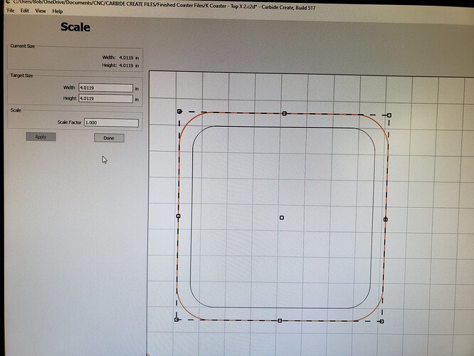
I used the offset vector tool to draw a square around the outside of another square exactly .25 larger all the way around. So the first picture shows the two squares. the inside square is a pocket about 1/8’ deep. The outside is the contour I’m trying to cut out. A little short of 1/2" deep. Note that selecting the square brings up a “scale” box.

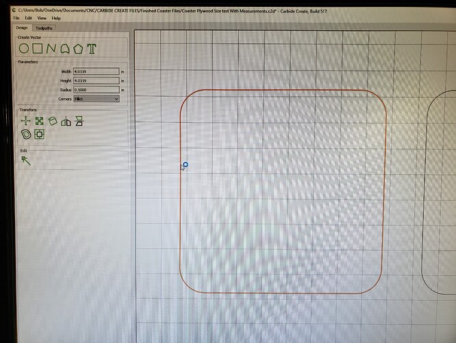
The 2nd pic shows the test square I “drew”.


Note how that selected square brings up a different dimension box. This configuration was the better contour cut.

BTW … what part of Canada? I have a cabin in Oxbow ME … just a stones throw from the border.

@oxbowbob In VCarvePro, there is an offset feature like the one you are showing, Bob. Draw one thing, then offset it inwards, outwards or both by a fixed amount. You’re right that the offset that I was talking about in my previous post was a cutting offset, frequently to be used when needing to join two pieces together and needing a bit of leeway so that they fit well.

I see the two screens in your post. They clearly are for different purposes. The first allows you to scale up or down the selected object. The second seems merely to report on the selected objects parameters.

ps. I live in Ottawa Ontario, about 9 hours from your cottage, according to Google maps.

@gwilki Correct … and I don’t know what the difference is between those two or why one would cut better than the other. I’m going to redraw what I’m trying to make by setting an exact square size using the second screen and then offset the middle. This is the opposite of how I did it the first time. That inside pocket is less critical than the overall dimension.

Yeah that’s a little hike from me. I’ve been by there going thru North Bay on my way to Cochrane. Got in a float plane and flew north. Grabbed a few of your fish up there. It was the 2nd week of June and was quite a shock when it snowed on Wednesday.

UPDATE:
It appears that everything that had any thing to do with out of square & the wrong size had everything to do with using the offset vector tool in CC to draw the squares.

I just quickly drew a few hold down clamps I wanted to try and make. Using CC I drew all the pieces using squares and radiuses (no offset tool). I cut the parts out of Pine and they were perfectly sized. Of course I needed to know how they would come out in Maple. Cut them using same bit and all the same feeds and speeds as before and contour depth was close to the same. The were all perfectly sized.

2 Likes