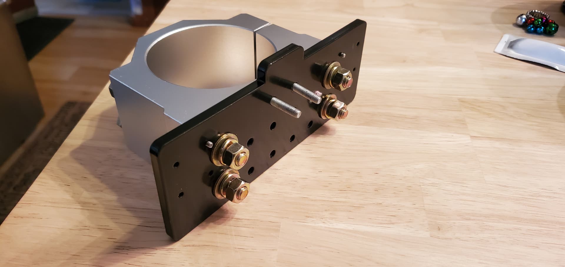
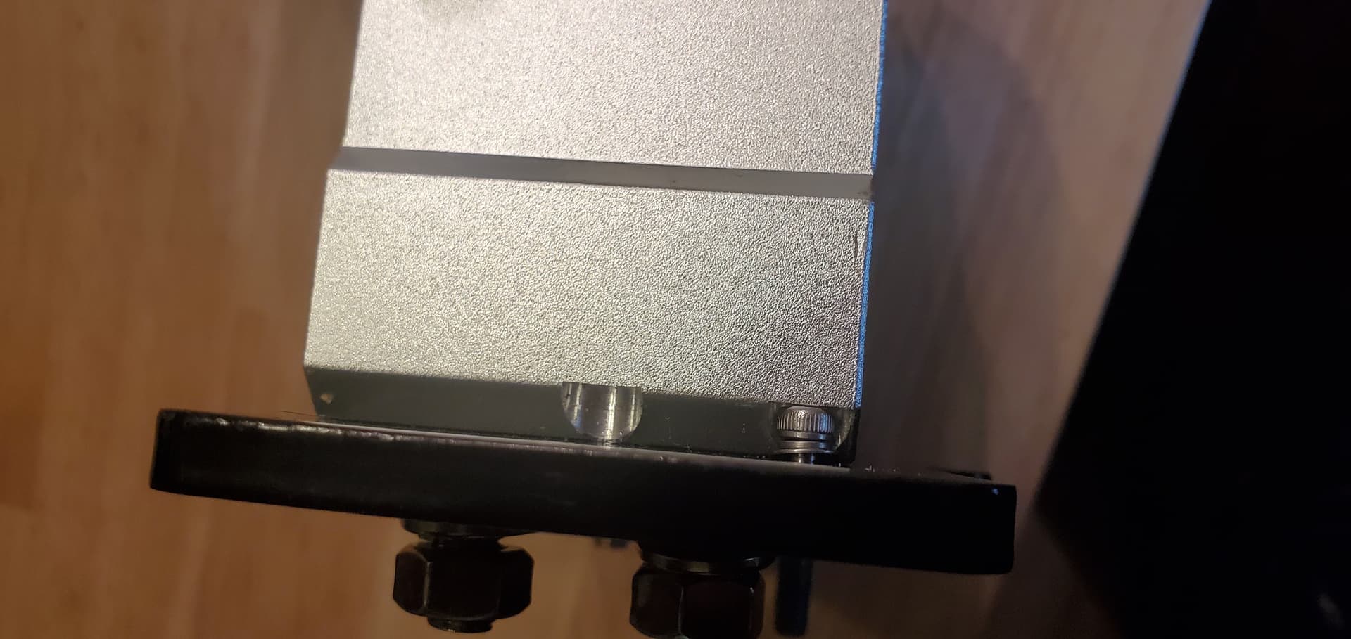
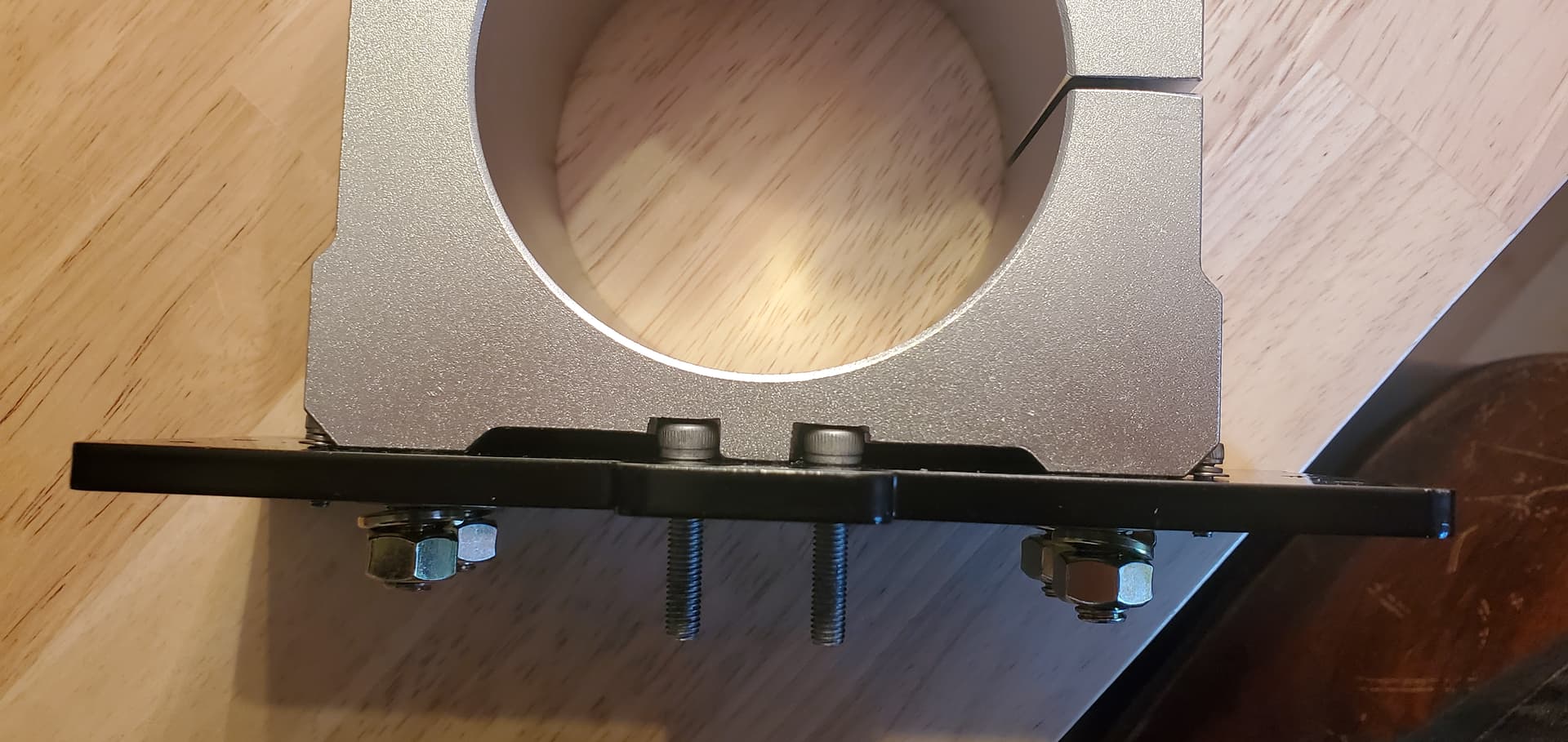
The Z Gantry Plate has been modified for the new spindle mount. I needed longer bolts and decided to just go with grade 8 hardned steel purely for aesthetic reasons since they were like $2 more lol
The washers look like they’ll probably interfere with the linear rails so I may only be able to use the small lock washers. Also, the bolts don’t extend further than the M5 screws for the Delrin anti backlash but so I am hoping they have enough clearance. Will post pics when I get it mounted.
@Blunderpunk Tks much, Jordan. Your spindle bracket looks incredible.
I guess one thing that I wonder about when reading all the tramming posts is the idea of variability, if I can call it that. In addition to the posts here, I’ve watched several videos on tramming CNC mills. Pretty much all of them emphasize the idea that greater accuracy can be obtained by taking the measurements farther from the router than closer to it. So, a tramming arm 15" long will give a more accurate indication of how far out the router is than a tramming arm of 4". That would make perfect sense to me if the only variable in play was the tilt/nod of the router.
However, that is not the case. The other variable is the flatness of the bed that the tramming arm is registering against. Now, I understand that the first step in this process is to surface the spoilboard. In an ideal environment, that would address my argument. Surfacing took out the flatness variable and left us with only the tilt/nod variable. I would accept that and admit defeat except that the flatness will not last. The MDF that most of us are using can change dimensions by more than the accuracy that many seem to be seeking before the tramming exercise is complete. (That may be a bit of an exaggeration, but not much.) Further, the MDF will not change uniformly across its area. It may swell more 12" from the router than it swelled 5" from the router. (In the commercial shop that I frequent, the corner of the bed closest to the entry door is measurably higher than the other corners - presumably because the frequent opening and closing of the door subjects that corner to more temperature and humidity changes than the other corners. Keep in mind that we are talking thousandths of an inch.)
I get that you will be modifying the Mill to an extent that it will be unrecognizable as a hobby-centric machine. I’ll be glued to my seat watching your progress. So, your efforts make perfect sense put into that context.
In all my ramblings, I was simply trying to put all this into some perspective. I don’t have a clue about whether I’ve succeeded.
I like shiny things yeah you lost me about 3 sentences in lol maybe one day that will all make sense. I’m still at the “bits are sharp and I cut wood” stage.
I understand what you mean and yes you are correct. Wood is not a consistent material and is prone to changing its dimensions under different circumstances outside of my control.
While it may not matter for this particular setup for long due to these changes, I still wanted to try it just for learning. Eventually this will have a metal bed to it once I have the money to drop on a lot of steel and epoxy. I am still debating rather pouring an epoxy granite table for it or just going straight to a 4’ x 4’ plate of hot rolled steel.
Also due to clearance issues with the back side, I had to reverse the bolts. So they go in from the back now which is a bit annoying because to remove them I now have to remove the entire Z gantry plate. This is because the bolts were too long and I don’t have the tools right now to grind them down. This also means that the nuts will clear the V wheel screws which stick out from their nuts. To save trouble in the future I went out and got some 20mm screws instead of 25mm. They don’t go all the way through anymore, but they should be fine and there are no more clearance issues.
I also replaced the M5 screws for the Delrin Anti-Backlash nut with some shorter ones so they don’t protrude so far out the back. Also in black. Everything black.
In regards to tramming and a reasonable tolerance to achive (I still dont have mine yet #67) what should a complete noob be looking for +/- .005" or upwards of +/- .05". Im a CMM Operator that works with mainly aluminum (easily affected by temp.) but the “lab” I work in is temperature controlled! My garage in the cold of winter has a space heater.
I understand this is subjective But there are some very talented Carvers / CnC ers ( how do you refer to each other?) in this group. What numbers are you happy with considering everything said in this discussion?
Most time, I try to achiev abolute tolerance of 0.1mm when cnc-woodworking. Wood is indulgent… if you have an inlay to carve, you can go with slight overlapping tolerances to achiev a snug fit.
Wrt tramming: If you have possibilities like @Blunderpunk I would also try to achiev these Nasa tolerances. Ending up with 0.1mm ripples when carving a pocket or something else is annoying.
However, I think it is similar to each other machine: if it isn’t that precise, you may end up with more extra work like sanding.
@CMFaub It’s really just until you get your desired result. Without a metal base made from something like steel in a climate controlled environment things will change over time. You could probably insulate your garage and get a mini-split heater / air conditioner to keep it controlled. That’s on my to do list, but for now my garage is cold. Got a wood burning stove because I thought it’d be helpful but it has crappy sealing and leaks smoke a lot so I can’t use it lol.
For a little router like this, tramming beyond a 1" radius is really not necessary because at most you’ll be using a 1" diameter bit max. So as long as it reads 0 at a 1" diameter I am sure your parts will be fine since the difference will smooth itself out. However the tighter you get the less tolerance you have to work with, so that’s why people will usually tram a wider area. The wider you go, the better result you’ll have.
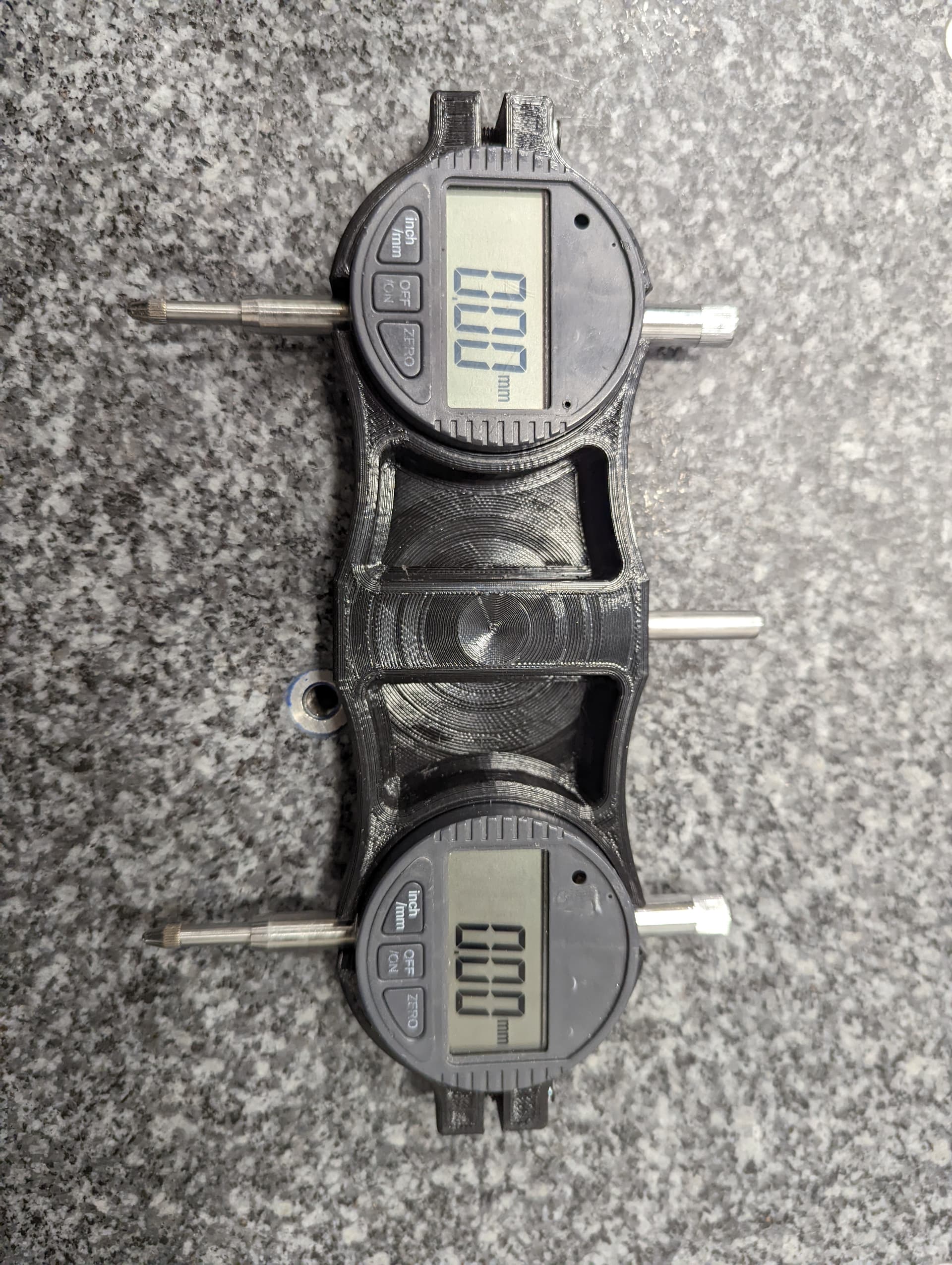
As per tram bar at a 15" radius I am +0.001" from one side to the other. After doing the math it worked out to be at a 1" diameter in the center only .00007" off from one side to the other. In reality it’s probably a little different, but once you get down to around in the thousandths, you’re not going to be able to see a whole lot of difference to begin with going smaller. For wood, these are okay. For precision fit metals? Not so much.
@JHahn Lol I’m not expecting them to hold I am just doing the best with what I have
Update: After ensuring it’s square with the tools I have I am really getting frustrated as it is still out of square and cuts like garbage. Below is an attached photo of what cuts look like on a random piece of scrap wood. I ran this program twice at 2 different heights. It’s just a surfacing job. One took off 1mm as a rough pass to flatten out any differences in height in the material, and the other took off .333mm to clean things up. I wasn’t expecting a clean and smooth finish from a piece of construction lumber, but the ridges are still there.
At this point it has taken me far too long to set this up and get any semi-okay results out of. Maybe it’s the way I am doing things because I have seen other people do good jobs with theirs but as far as adjusting for square goes even with the modifications I did this thing has been down right awful.
I also tried the same program fastening it down in all 4 corners just to be sure that wasn’t an issue.
Same if not worse results.
I am about at my end with this machine. I’ve sunk too much money into the thing for it to be performing this poorly. 5 months of troubleshooting and not a single actual job done yet.
@Blunderpunk What is the bit size and stepover, Jordan? What feed rate and spindle speed are you running in that video?
I realize that your machine and mine have little in common, but I do a lot of 2.5D carving with quite intricate details and I do almost no sanding. That’s not to rub it in. My experience shows that it is possible.
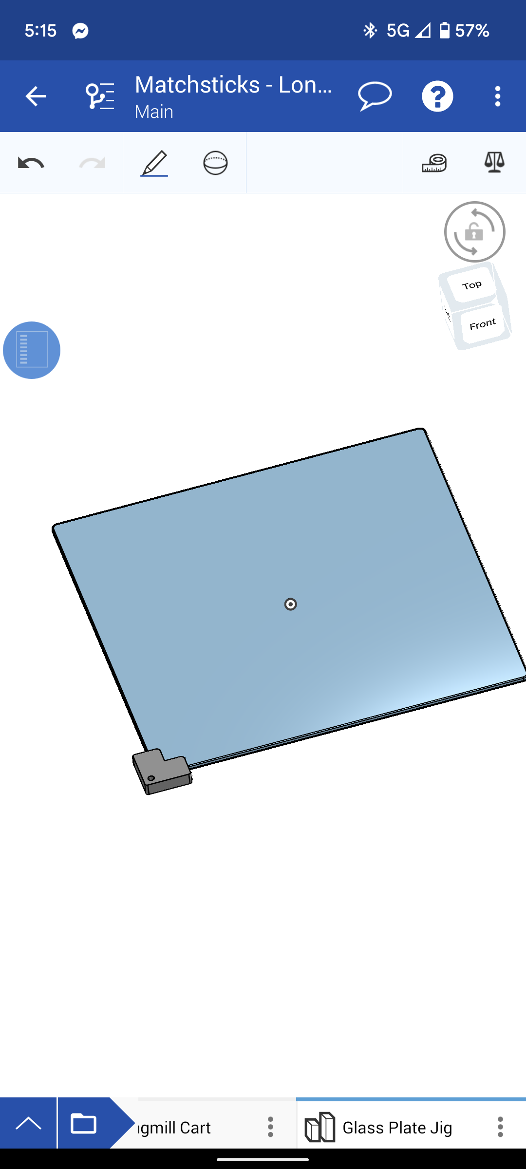
So I realized I don’t have my Longmill yet, but it sounds like tramming is something that I’m going to have to learn pretty early on. So this is what I’ve put together. Thank you very much, thingiverse and 3dprinting.
This is a good idea! Using screws to finely adjust the leveling of the glass will definitely be better than lifting it with shims that can be tough to move under heavy glass.
@Blunderpunk Tks for the link, Jordan. I asked because I couldn’t see if the cutting edges went all the way across the bit, or at least that they overlapped. On this bit, they do not. So, and forgive me if I am telling you the obvious, the stepover is critical to making this bit do a good job. I played with the pic from Amazon in VCP and figure that the carbides are roughly 1/4" long each. So, there is a gap between them where the bit does not cut of about 1/2".
I don’t know what stepover you are using, but I would try again, using a stepover of no more than 25%.
If you do try, please post how you make out.
@gwilki I will try this. I was trying at 50% at the moment however I didnt think this neccisarily mattered because shouldn’t the bit be taking out the entire width and not have to collide with the center at all?
@Blunderpunk You can play with the stepover to get the best result. I picked an arbitrary 25% only as a starting point. That bit leaves about 1/2" from what I can see of uncut material under the centre of the bit. If your stepover/overlap does not take all of that out on the next pass, you will get ridges of uncut material. In your video, it looks like that is what is happening, but it’s difficult to be sure.
I have the smaller surfacing bit sold by Sienci and have it set to a 30% stepover. The carbides on my bit have very little gap between them. I get very smooth results when flattening the burl slabs that I have been working with lately. YMMV, of course.
@Blunderpunk With a bit like that, that’s what I would start with. That may be overkill, though, Jordan. You can experiment. If you do that, and get good finishes, then at least you have a starting point for increasing the step over.
I appreciate that if the best stepover is the width of each blade, in your case I think that’s 1/4", you sort of lose the benefit of having the large diameter bit.
Firstly thanks for having me remember to remove my name off a public forum. I wasn’t aware that was on here lol
I have been working on squaring up the spindle and it’s mostly square now. There’s not a lot of ridges and things are a tiny ripply so I still have some more work to do. But it’s far better than before.
This is a piece of construction lumber so it will never clean up well, but there are no ridges and just the tearout along the edges.
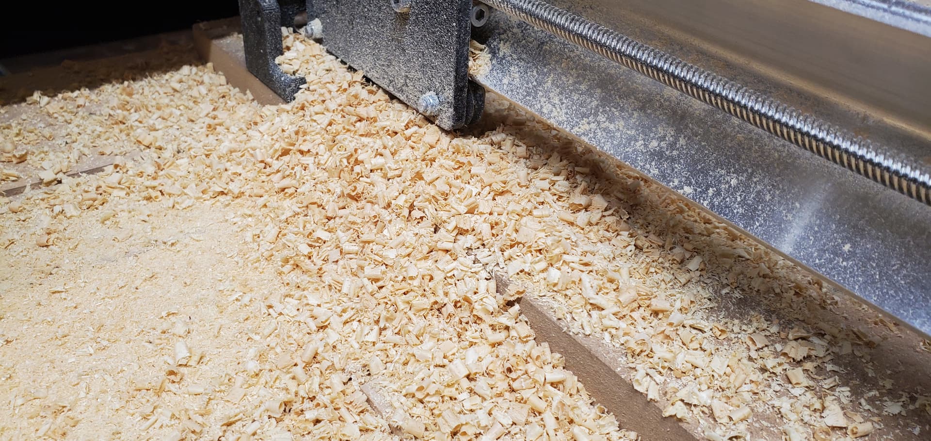
Other than that I can do 100% DOC (.249 is what the tool read on the calipers) @ 6.95mm step over (the tool measures 7mm on the cutting blade minimum between the three). I found that 50 IPM @ 9000 RPM makes good chips. It’s a little different for surfacing and I need to play with that but for slotting it’s great!
The sawdust was from a very thin pass. I guess I could up the feed rate on that since it’s not very deep and can afford to take off more material?
Unfortunately it got knocked out of square when my program exported with a wrong setting and crashed the spindle pretty hard. Luckily no spindle damage just needed to readjust and make sure Fusion stops being stupid! If anything I am okay with sanding the small ripples out for now until I get a more sturdy setup going.
In other news lubricating the lead screws and nuts allowed me to rapid the machine much faster without any binding. I will be seeing if I can make a modified nut out of something like brass with a wiper for the dust and an inlet for lubricant in the future.

 except that the flatness will not last. The MDF that most of us are using can change dimensions by more than the accuracy that many seem to be seeking before the tramming exercise is complete. (That may be a bit of an exaggeration, but not much.) Further, the MDF will not change uniformly across its area. It may swell more 12" from the router than it swelled 5" from the router. (In the commercial shop that I frequent, the corner of the bed closest to the entry door is measurably higher than the other corners - presumably because the frequent opening and closing of the door subjects that corner to more temperature and humidity changes than the other corners. Keep in mind that we are talking thousandths of an inch.)
 yeah you lost me about 3 sentences in lol maybe one day that will all make sense. I’m still at the “bits are sharp and I cut wood” stage.
 ) what should a complete noob be looking for +/- .005" or upwards of +/- .05". Im a CMM Operator that works with mainly aluminum (easily affected by temp.) but the “lab” I work in is temperature controlled! My garage in the cold of winter has a space heater.
 how do you refer to each other?) in this group. What numbers are you happy with considering everything said in this discussion?