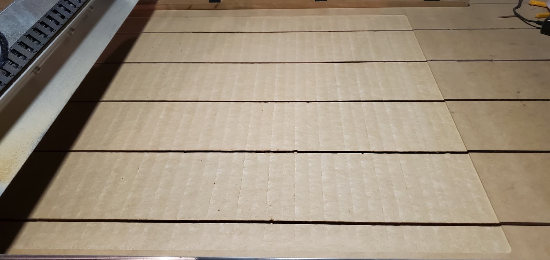
My spindle is terribly out of square with the XY axis. This is creating terrible finishes on my spoilboard and work pieces. Without modifying the machine, is there a way to get the spindle squared up to the rest of the machine or am I just out of luck on this thing? It’s the only thing I have left before I can use this machine and it has been forever since I’ve put it together.
Adjusting the V-Wheel eccentric nuts does not make a difference enough to solve my problem and is not a good way of going about this as it changes the tension of the axis itself to move properly. I have tried shimming the spindle inside the spindle bracket, however this is not the easiest thing to do and does not allow precise adjustments since the whole thing has to come apart and might be different next time. I have also tried changing the point of height at which the spindle is clamped in the bracket with no improvements.
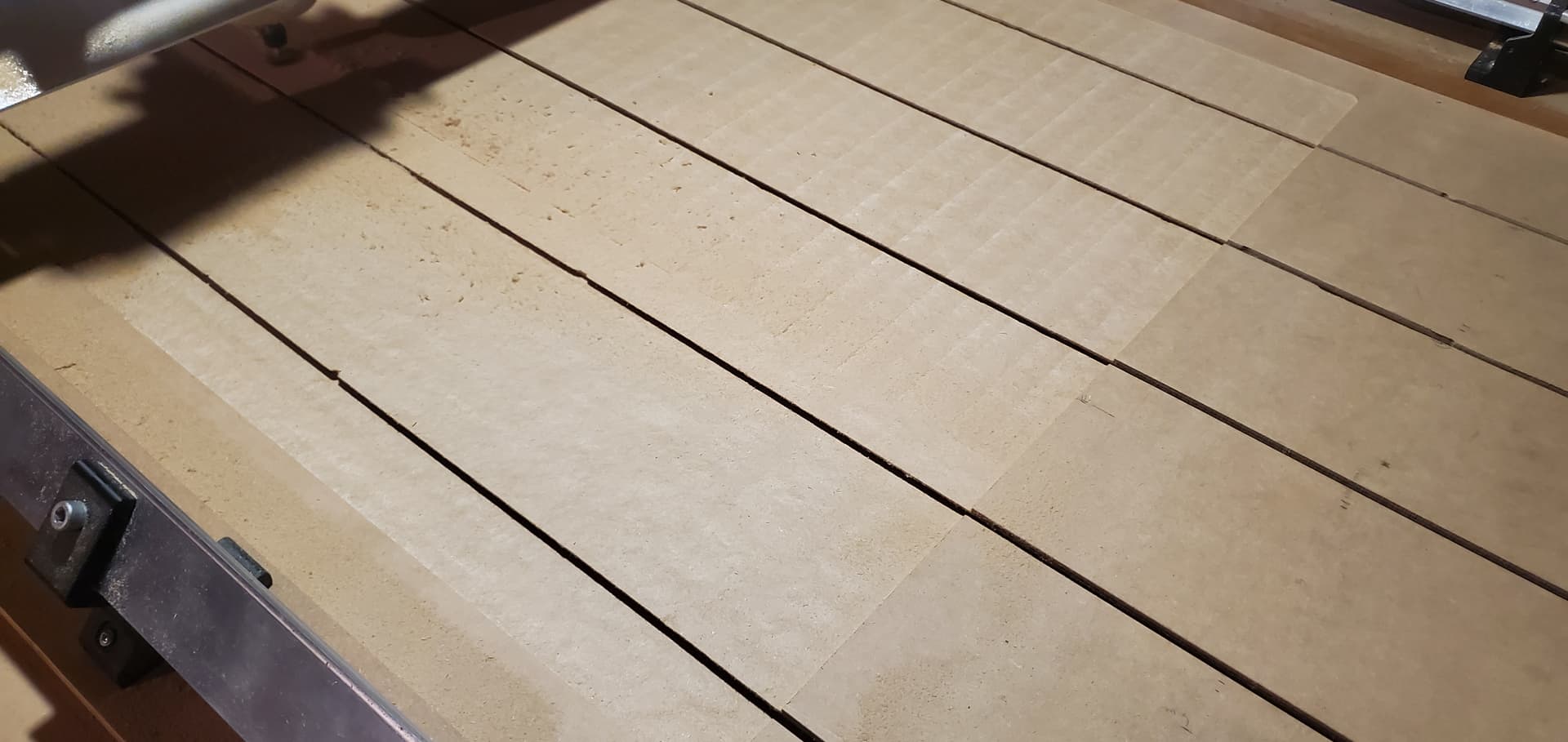
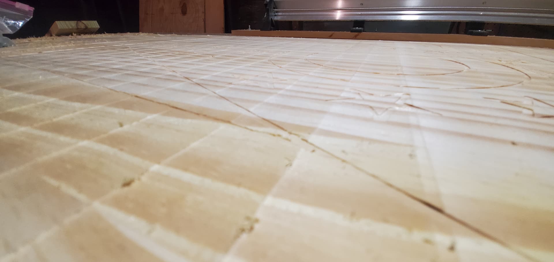
In the second picture it can be seen that taking very light passes in the opposite direction helps due to the way it is out of square but it is out of square with both X and Y axis can be seen in the last picture.
Please help. I am running out of spoilboard to surface from tinkering.
I do not see exactly how this is going to help raise / lower the X axis rail to balance this out?
For squareness in the Y direction I was going to take the mounting bracket apart and drill an extra 4 holes above the delrin anti-backlash nut so that I could mount an additional bracket. Afterwards, shim stock can be used to square up the spindle to the Y axis.
The problem I am left with is the spindle squareness on the X axis. Once I add a second bracket, there’s not going to be an easy way to rotate it left / right since there are now 2 brackets that are going to need to be aligned which isn’t going to work that way. I could raise the gantry on one of the sides, but I don’t think that is a good solution because if the table is not perfect then it will show more as opposed to being flat relative to the X axis rail. I essentially need a way to rotate the entire mounting plate a couple of degrees.
You’re talking about tilting the router around the y-axis. For me, it looks like you need some tilt around the x-axis as the ‘lines’ go sideways (the routerbit is lower to the front and higher to the back, not to the sides…).
For squaring with the y axis, I slightly drilled out the holes for the bracket - but I just use one bracket not two.
I am drilling out 4 new thru holes for it to mount into with a nut on the back.
Shim stock can be placed under the bottom between the plate to shim the spindle out to adjust the nod (forward/backward angle). The side to side can be adjusted by having a slight amount of play in the thru holes that when tightened just enough can still be tapped with a dead blow to pivot it and then tightened to its final angle.
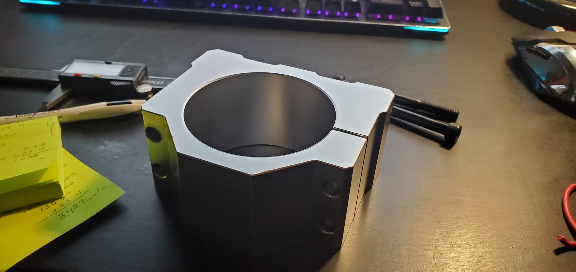
This new mount should also provide more support for the spindle as opposed to the original spindle bracket which being so thin and with only 2 points of fastening is prone to flexing. Now my limitation is the flexing of the entire Z carriage considering it’s only held on via v-wheels and not a linear rail.
I also realized that despite my level saying the table was level, the gantry is not for whatever reason on the Y rails. So I am fixing that with some shims as well.
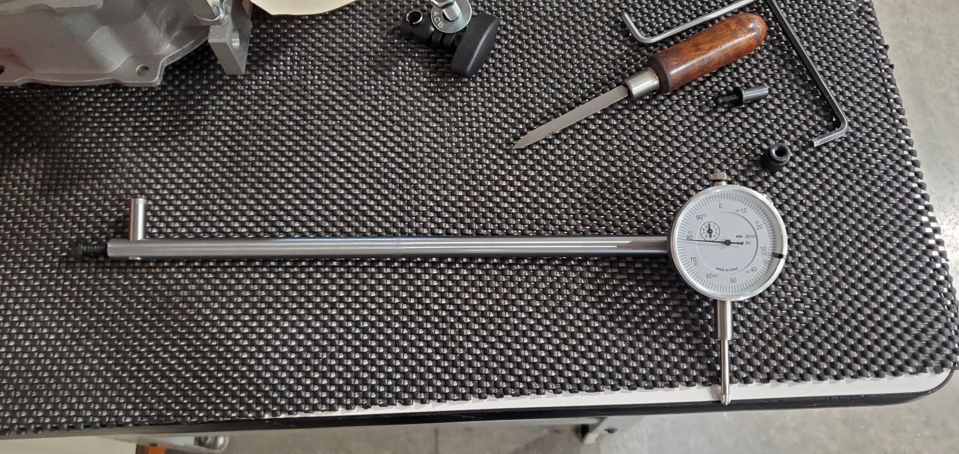
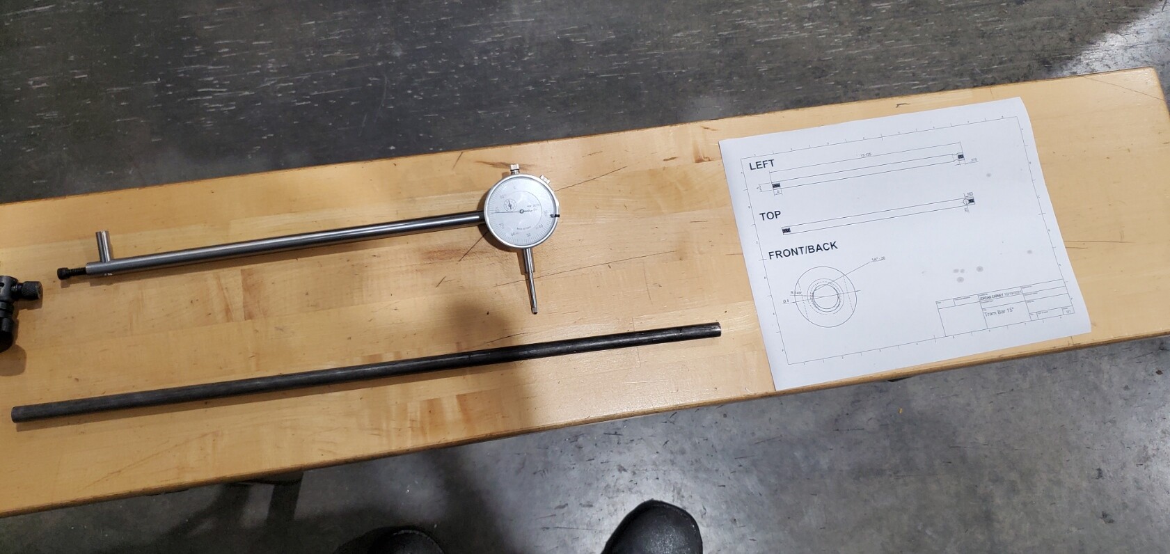
I made a tram bar at work on the manual lathe using some 3/8" stock and tapped a hole in the end to fasten a dial indicator with a plunger probe to the end. Rotating it 180 degrees at a 15" radius I was able to get the X axis within .001" difference from one side to the other. If I did my math correctly, on a 1" endmill at that angle it came out to being like .00007" difference between the edges of the endmill which I think is an acceptable level.
Sadly it is too big to go completely under the X gantry so I have to walk around the whole table to read it, and I am unsure of how I cam going to do the Y axis like this. Maybe flip it at a very high angle.
Your new bracket looks professional and the accuracy is awesome, well done.
However, there is one point that comes into my mind:
If you shim the bracket to orthogonally align the spindle with the y-axis, you may result with the carriage (and the linear rail in z-direction) beeing missaligned to the bit… such that the up and down movement of the bit also also causes a slight forward and backward movement of the bit.
Did you check this?
If this is the case, I would still prefer to tilt the whole carriage, not just the bracket.
From what I can see there are two options to look into. First being, are your linear rails perpendicular to your spoil board? You can have a quick look at this by taking a square, putting it on your spoil board and running the other part of the square against the rail itself. This should show you perpendicularity if it’s good. Move on to the spindle. Now you want to make sure your spindle is square to the spoil board. To do this, put your arm indicator in the spindle rotating it 0 to 180. That will show you the difference and should tell you which way to move your router if it’s the router.
Again, don’t assume your linear rails are perpendicular. If they are on an angle and then you set your router to a different angle, then your router isn’t running parallel to your linear rails.
That is probably a lot to take in. I apologize if this explanation gives you more questions. Feel free to ask if you have any other questions. I’ve been into a toolmaker for 25 years and I’ve been indicating heads on Bridgeports for vast majority of those years
It is very important that you don’t check perpendicularity. Now that you’ve machined your spoil board, You have to check it before you machine it or else you will be setting your spindle wrong because the machining is wrong at this point remove that spoil board start from scratch off the tabletop. then reinstall your spoil board and recut
Good point. Yes, part of the problem is the Z Carraige rigidity.
I can visibly see it flex when the spindle is mounted. Regardless, the new bracket is going to hold the spindle more rigidly to the plate. I did not make it, though. It came with a different spindle I bought.
Not exactly sure how this can be fixed though, since the plastic V-Wheels are the only thing that can adjust this. The X axis itself is not twisting. It’s just the fact that the Z Carraige is held on by 4 small plastic wheels that don’t have enough adjustment to compensate for this.
I don’t think you need to order a machine a square at this point regular Carpenter Square will do. You also don’t have to make these adjustments via the v wheels The gantry itself that holds does that holds the gantry can be lifted one side or the other by shimming under the legs of the x travel.
This is a lot of speculation on my part as I actually don’t have my machine yet and I don’t know the connection points between the y-axis and the x travel. How is the gantry attached to the quarter inch plates that hold the v wheels that ride along the x travel? Is there any adjustment there?
Adjusting the V Wheels will change the X and Y squaring slightly within a couple of degrees.
This is because in addition to be raised up off the rail making the X axis angled, having the front or back wheels at different heights can help balance the Y squaring as well. It is not intended for that though, and yes like you mentioned shimming the feet on one side is a better option.
I suppose it is actually kind of difficult to see in the pictures before but I have my feet that hold my Y rails on a platform of MDF raising the whole gantry 1/2", and so that it’s more easily adjustable if I wanted to move the machine to a different spot on the table. That idea went out the window when I realized how difficult it is to change that so in a future build I will be making a cabinet that’s just the space needed for the machine and put caster wheels on it to move it around my garage. Anyways, I have shimmed one side up in the middle as an experiment to level out the X axis and I was able to get it within 0.001" of a difference with the tram bar I made, which measures out to a 15" radius. I made it 15" since the diameter of the dial indicator is about 2", so leaving a little over 1" left gives me room to use the tram bar completely while the spindle is centered. This means the spindle would be sitting at a 0.00191 degree angle if my math is correct. Shrinking that down to a 1" diameter that means one side of the 1" end mill (facing bit) would be only 0.00003" higher than the other. Divide that in half and we get 0.000015" off from the center of the tool in either direction which is obviously good enough.
Most people I see tramming their machines in a small radius because it’s a small machine and fine adjustments are hard to make when there isn’t a developed mechanism for it, and if you can only use a maximum of a 1/2" to 1" surfacing bit then why bother getting closer right? But the flatter you are from a further distance the less of any noticeable angle you should have at the center. Like how the Earth is round but locally it feels flat.
Now I just have to do that for the rest of the feet, and figure out if that effects the rigidity of the mounting at all because it probably does sitting up on stilts.
One thing that is not being discussed in this conversation is that we are working with wood or MDF. With no disrespect intended, some seem to be trying to adjust this primarily-wood-working machine to tolerances that NASA would be proud of. It’s a noble goal, but I wonder how practical it is. In my basement shop, which is heated and humidified to roughly the same degree as the rest of my house, the temperature and humidity still change throughout the day, let alone over the seasons.
I do quite a bit of non-CNC-related wood working. It is clear to me (and not exactly an insight) that wood moves, period. There is a reason why we attach table tops with slotted fasteners. If we did not, wood movement would destroy the top. In the same vein, we are taught never to apply a finish to only one side of a board. Doing so invites warps, bows and twists since the non-finished side will react to temperature and humidity changes remarkably differently than the finished side.
Most of us here are using MDF for table tops and/or spoil boards. MDF swells, particularly after the first surfacing takes off the factory-pressed surface. Absolutely nothing can be done about this in any practical sense.
In another thread on this forum, someone pointed out that the large temperature swings that occur in the shop environments of some of us can affect how tight the delrin wheels are. I submit that delrin is likely far more stable than the MDF that we are registering our tramming devices against.
Finally, any of our projects that are carved into wood, as opposed to MDF, plastic, foam or aluminum, will move by the time we can take them off the table. I’m not saying that they will move by orders of magnitude, but to expect that we can carve into one side of a board, introducing stresses into that board, and releasing stresses from it, and not have it react is ignoring reality.
Add to all of this that many of us likely do not scrupulously clean and maintain our machines to laboratory specifications and it is very likely that our efforts to tram our machine to .001" and tighter tolerances will be obviated by the end of a project-filled day.
I’ll get off my soapbox now. I want to repeat and emphasize that none of this rambling is intended to show any disrespect for anyone here trying to bring their Mills into very tight tolerances. I applaud the ingenuity shown to achieve these incredible results. I envy the engineering educations and abilities of all of you attempting and succeeding in these efforts. I simply wanted to put down my thoughts and to, perhaps, calm some of those reading these discussions that believe that they cannot do excellent work and have a great deal of fun with their Mills because they are unable or unwilling to expend the time and effort to achieve the discussed degrees of accuracy.
My flame retardant shirt is on. Have at it.
Edit: It just occurred to me that if you are using your Mill to create printed circuit boards, you may well need accuracy to .001". I’m still not convinced it can be achieved using MDF as a base, though.
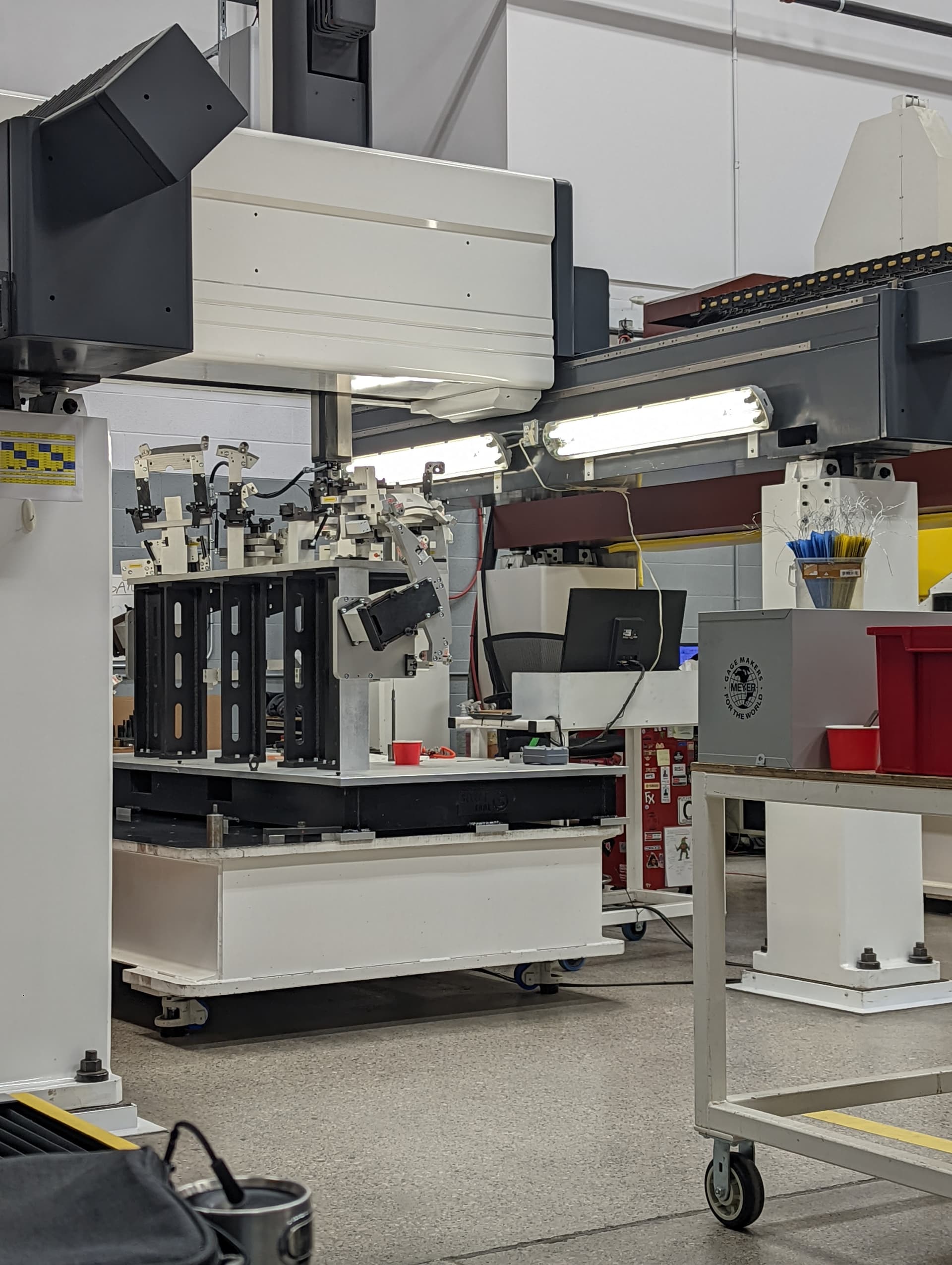
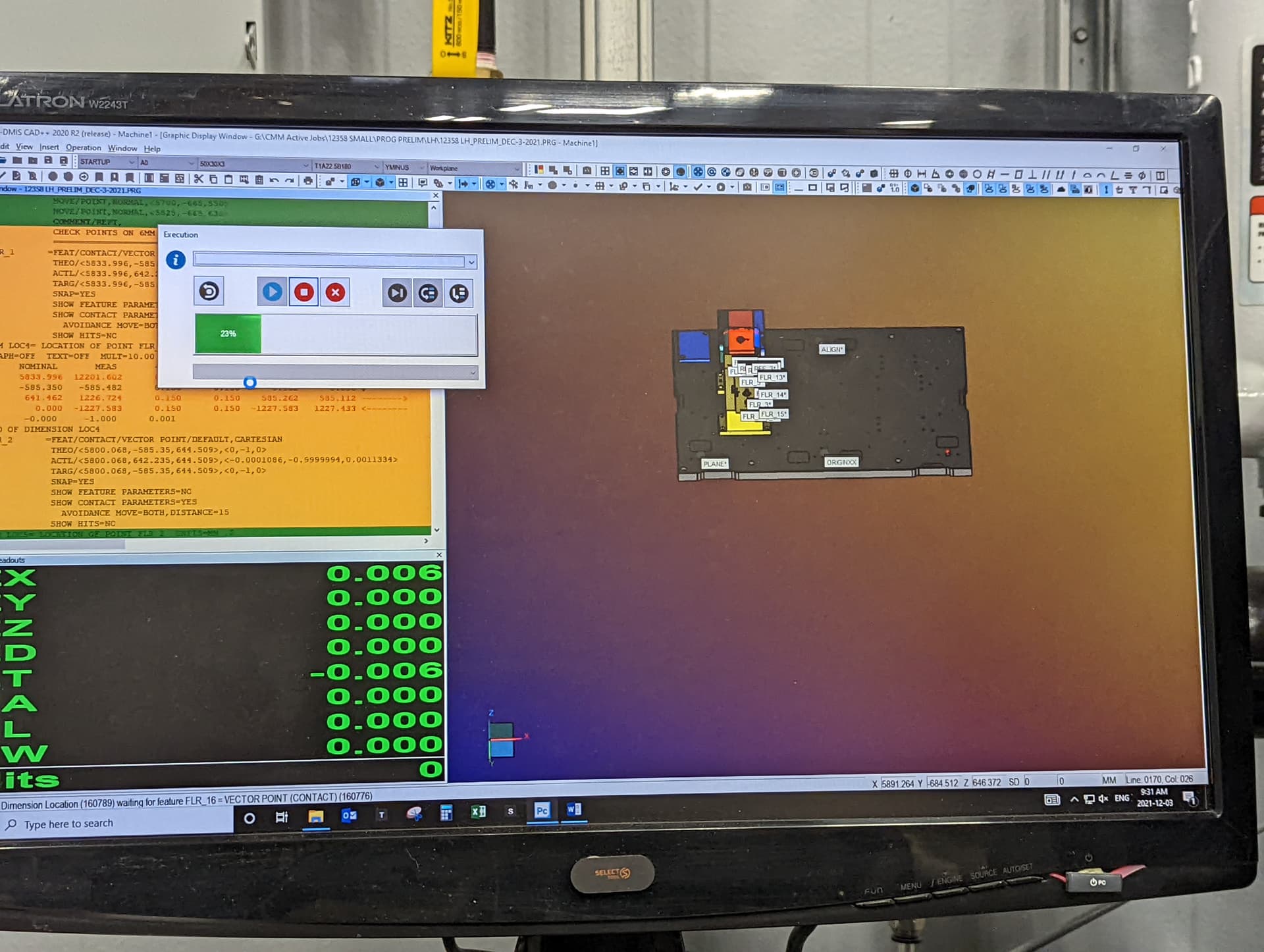
All great points… For context this is the machine I run at work which is qualified for holdng the tolerance of .000123". This machine cost over a million dollars!
Newish guy here… take this suggestion with caution…
I had the same issue when I set up my longmill. Those ridges running left to right on mine. My solution…
No laughing…
I placed a level on top of my router. It showed that the router was not sitting perfectly in the mounting bracket. I loosened the bracket and ever so slightly adjusted how the router was positioned. Once it was level I tightened the bracket back up. No more lines and I haven’t had the issue since. I check all the wheels and the router with a level before each cut. Only takes a minute.
I’m sure this isn’t the right way to fix the issue but it did work for me.
On the makita router metal flares out at the top slightly. I found that moving the router up slightly was the key. I actually met a gentleman through marketplace who also has a longmill and we have become friends and often discuss projects we have going on. (Shout out to Nick M) He is on here too. He is more experienced than I am and it was his suggestion to try that minor adjustment. It worked.
PS… if you see this Nick I scored another load of wood. Stop by and grab some I’m buried at the moment lol
I wonder if removing and reinstalling the dust collection boot can knock it out of adjustment. The magnets are pretty strong and exert a lot of force on the Z mount. I noticed my machine now appears to need adjustment. I’m going to clean the rails and then remount the router.
@gwiliki I understand that. This will eventually have a metal base when I can find a metal supplier near me and a way to transport a 200 lb. Slab of steel.
But for now, it’s wood. For now I am just doing this for best practice. I’m.not aiming for extremely tight tolerances, because plastic feed and wood bases aren’t getting me that. Nor will the stepper motors in this machine allow it.
I look at it as if I can level it out to a 15" radius, then why not? I have a sheet of glass I use right now that is a 30" diameter to use as a flat surface so the machine has something flat to reference as well.
Additionally, I was considering completely pocketing out that spoilboard area on the table in favor of making it a slot for drop I’m replacements. My original table idea was thinking for longer stock I could just move the machine around, but obviously that isn’t a good idea now that I know more about how these work lol