I’m having some trouble getting my new altimll 2x4 to make exaactly what I program.
Sorry for the long post, but theres kind of alot to this.
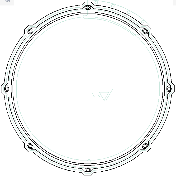
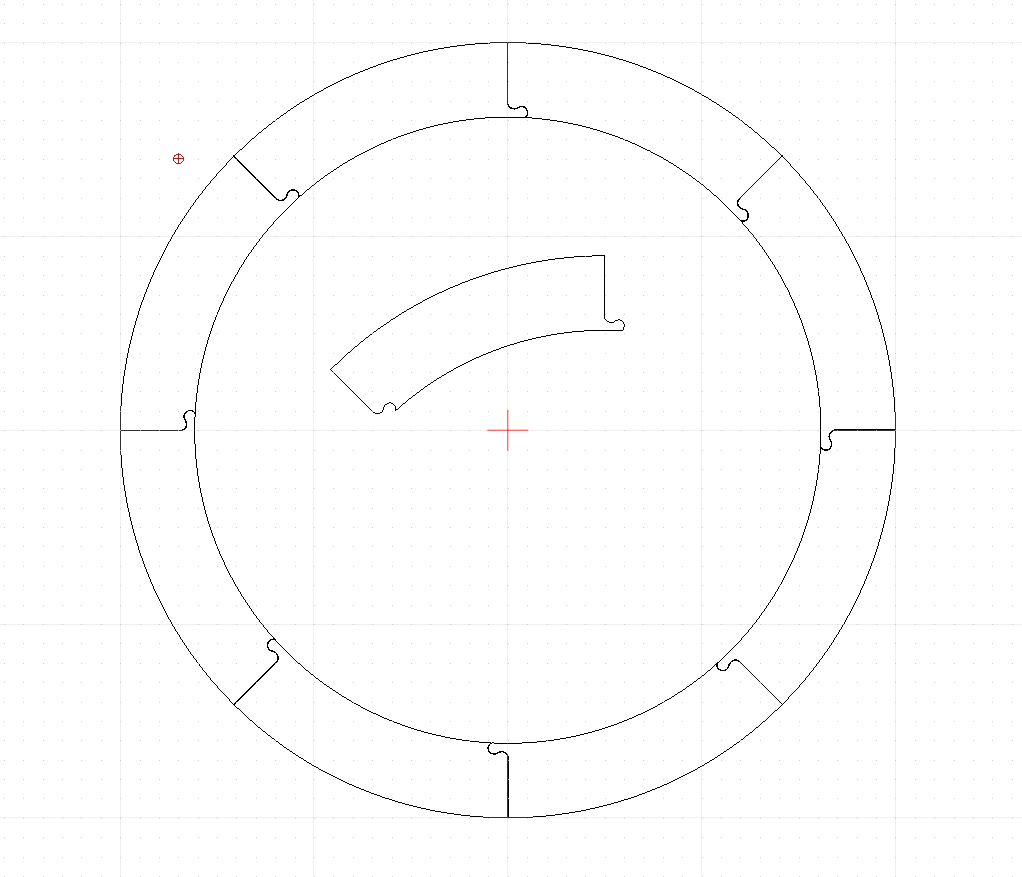
So I make custom drums, and the primary reason I bought my cnc was to more accurately and consistently make parts. The main part I am concentrating on is a wood rim. I have r&d’d my design over many years using an overhand router setup I built myself, but realized I could not keep it consistent enough for any real production. The rims are made of 4 layers of 1/4" hardwood that I have constructed from octagons. I was hoping my cnc would make this easier faster and more consistant, but I can’t get it to actually come up with the size I have programmed. Here is my vectric design:
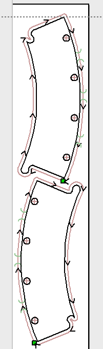
So I designed the individual piece using the drawing, using angles created from an octagon layed inside and outside the rim dimensions, isolated the part of it I needed and created this file to cut them out of small peices of 1/4" maple,
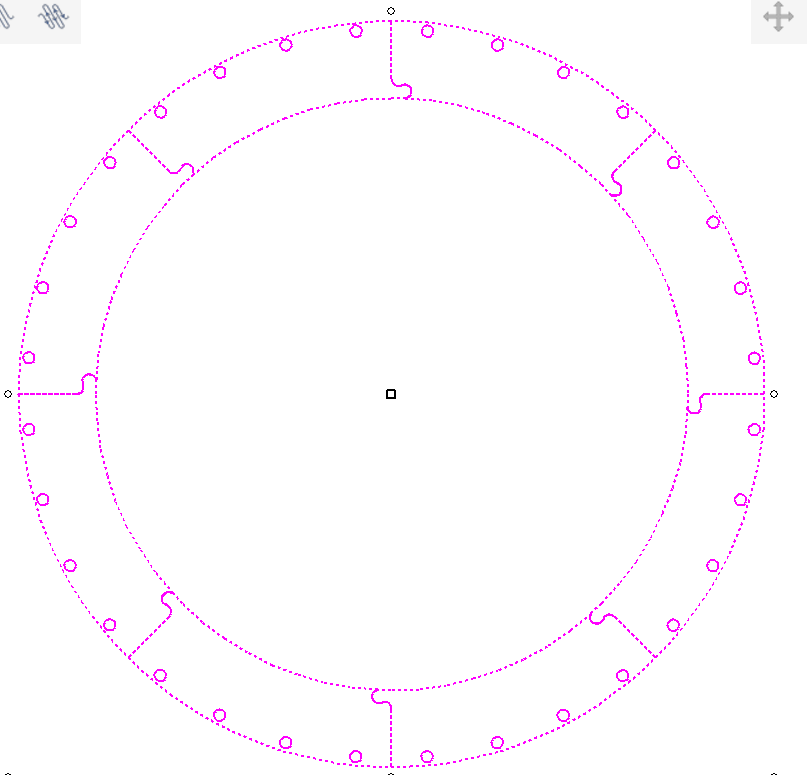
but when I make the part, It comes up smaller than needed to create a full circle. The angle is also just a hair off. I even created a circular array to check my measurerments and it seems like my design is right, even the little reference points have a little room in the joint(.002’) so they will go together well.
but my actual peices dont join correctly into a circle. So it seems like my machine is not cutting exactly what I am designing. How do I check and adjust my Machine to make it cut the actual dimensions I need?
Thanks. I have Just gone through that process. Just a note for us inch guys - In Gsender 1.5.1 the distance travelled asks for a measurement in mm. Don’ believe it! It really wants inches. I inputted the mm and it really screwed up the eprom settings!
I re-calibrated and it does seem much better. still not perfect. Am I expecting too much?
I’ve also noticed something strange about the Zed axis. Both of the toolpathes are set to the same depth of cut, but the holes never cut all the way through. I have gotten into the habit of setting my zed zero, and then taking it down a couple clicks to ensure that it cuts clean through. Is this normal?
I have a longmill and it came out of the box totaly diled in as accurate as I could ever wish or replicate.
I completed a long sign tile project recently and it had a starting date of the sports club on it. 1964.. so I set myself a goal to try and end up with a board 1964mm long.
This size came out perfect, even after needing to feed the board over the machine bed 3 times to be able to carve the 4 tiles. Now I know, this is partly because I am extremely good at moving things, but even when you are so good, you can move wood at nanometer accuracy, if the machine can not carve at the same resolution, you wont win the challenge.
This is to show that it shouldn’ t be a problem for you to get accurate enough and repeatable results with your machine.
On cutouts: The problem of not going all the way through, and having to set extra depth. If you set your z-zero on top of the material to do cutouts, you need to know exact what the thicknes of your material is. I don’t like measuring that accurate so for cutouts I set my z-zero at the machine bed and have my inaccurate thicknes play out above the material.
To keep things save, I set the material thickness a wee thicker than the material actualy is. This results in some air cutting before the actual cutout starts, but cutouts are not that time consuming that a wee aircutting matters to me.
When your machinebed is level to your machine, your cutout will be perfect every time without touching the bed. It’s magical.
I’ve used my CNC machine for 3 years now, first year was a genmitsu, the other 2 was my own design custom CNC. I was chasing that 0.001 mm of accuracy, big big mistake. I endet up with 0.02 to 0.05mm of accuracy, which is acceptable.
And that is in aluminum, cut fast.
So, if you, for some reason want that type of accuracy, just don’t.
@Shellshock if you orient your drawing horizontally instead of vertically, does it make a difference? It might give you an indication if you’re lacking precision in the x axis or the y axis.
Thanks for the info, I will definately try using the bed for cuttouts. Question, What if your project also uses a toolpath like a quick engrave? How do you deal with multiple types of toolpaths?
I thought about this too. It really shouldn’t make a difference if the machine is accurate.
Since my initial post, I have gone through and tuned my accuracy a bit, and it is much better.
I like using the vertical orientation because it makes it easier to keep 2 setups on the machine bed at once.
Could the problem be with your drawing? I rarely use vCarve for the CAD portion of my designs. I prefer to use a proper CAD program, which are usually more accurate. I use qCAD, which is a paid (and supported) fork of LibreCAD.
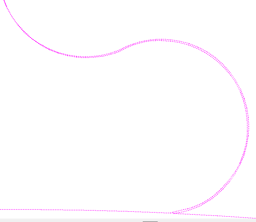
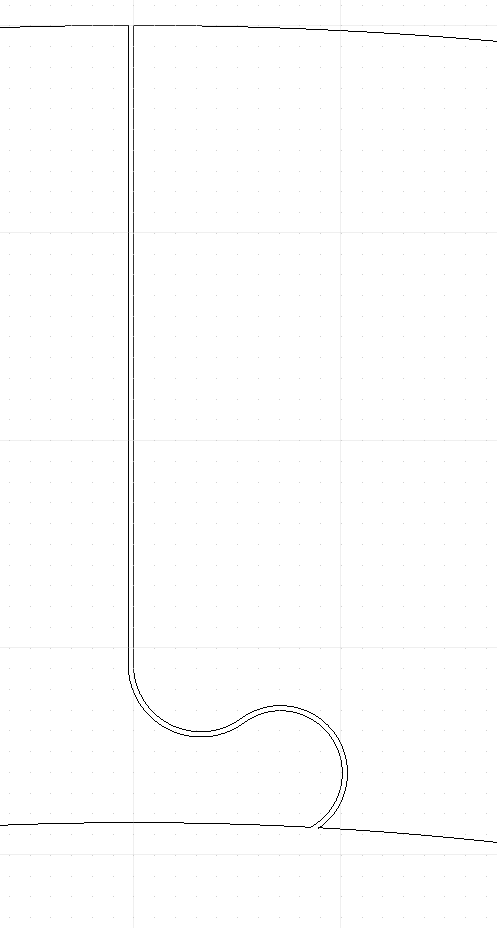
From the drawing you posted above, you can see that the lines between the mating parts are not equidistant throughout the length of the vector. That might be part of the problem.
If you fix that, maybe the parts will mate together better. But you might also need to use offsets so that there is some play in between the mating parts.
If you stack your parts, are they all exactly the same? If they are, then accuracy of the CNC may not be the problem. It could be the drawing.
I’d be happy to make a DXF version of your file if you want to try it.
I design the cutout as the last toolpath. Before calculating it, I change the material spec sheet z-zero into machinebed and say no to the prompt that all other paths need to be recalculated. Calculate the cutout and save it with a warning that it has bottom z.
My design software is vectric vcarve pro. Your design software might deviate.
Yes it certainly could be the drawing. I was hoping someone with cad experience might chime in, so thank you! Do you think that the mating lines should have a gap? if so how much?
I don’t know much about offsets, so any info would be appreciated.
The parts are all coming out the same now, and I’m very close to having a complete circle now, so I think half of my problem is fixed, the other half is getting the drawing or offsets, (or both)corrected,
Thanks!!
There probably should be a gap between mating vectors, especially with wood. How much of a gap? I dunno. You’d have to try different gaps sizes to determine that. A lot of factors come into play here: wood species, moisture content, time to assembly, adhesive that will get used, etc.
Yeah its a dangerous game using one file for both top and bottom z-zero, but I am too lazy to make two files just for the sake of keeping it seperated.
I make it pretty clear in my file naming that something is a bottom or top file, and I usualy do my cutouts las (both at design and during machining) having a top zero on a bottom file wont end in drama, just air cutting and looking stupid again.
Here’s what can easily be done with qCAD. While vCarve has its strong points, creating vector drawings is not it (at least not to someone with 35 years experience with CAD software).
Note the constant gap between the mating parts. It would even be possible to vary the gap of the “key” but minimize the gap of the straight line as much as possible.
@Shellshock I will respectfully disagree with @Chucky_ott on two points. First, Vcarve is perfectly capable of producing those mating parts. I have made dozens of jigsaw puzzles that prove that. Second, IMHO, the last thing you want to start your project with is a DXF file. They are messy, node filled files that will not play well with Vcarve. You can take the time to clean them up if you like. If you must import a 2D file rather than create it yourself, look for an svg file.
The other issue that has not been covered is the size of the end mill you are using compared to the profile that you want it to cut. An easy way to see how and where your endmill will cut in Vcarve is to turn on the profile view that shows as a dark blue line. (I don’t have access to Vcarve in my current location, so I am not using the proper term.) This will show you precisely where the end mill you have chosen will cut. Another way to see this is to create a circle the size of the end mill you want to use and move it around the profile. You will quickly see where it will and will not cut.
All of this presupposes that your machine is properly calibrated and maintained. If it is not, none of what I have said has much relevance.
I don’t have Vectric anymore but I used to. I know it has an offset tool that you can use to get the even gaps @Chucky_ott has shown. You might have to use ‘node view’ or whatever it’s called to isolate the curved part and then the offset tool will create another vector with a constant gap on whichever side you choose in the dialog for the tool.