Hello CNC’ers! In this video, our very own Bucky’s Customs (Dana Andrews) shows us how to make a quick reference grayscale material test chart for your laser using the Lightburn software. This video will be helpful to those who have trouble choosing the right speed and power settings for laser projects.
To learn more, watch the full video linked below. Make sure to subscribe to his YouTube channel linked below for more videos on CNC machines, software, tutorials, and other cool things.
Thank you for this link. I watched the video and read where Bucky had some issues with his process and asked for input for a solution.
One of the replies recommended using LightBurn to talk to the Long Mill laser instead of exported gcode from LB and loading it into gSender to send to the Long Mill laser. Bucky replied that he was doing that now.
Also, LAHobbyGuy has free files to run in LB that give more intormation on feeds and speeds. These may get rid of the problem that Bucky mentioned with his file.
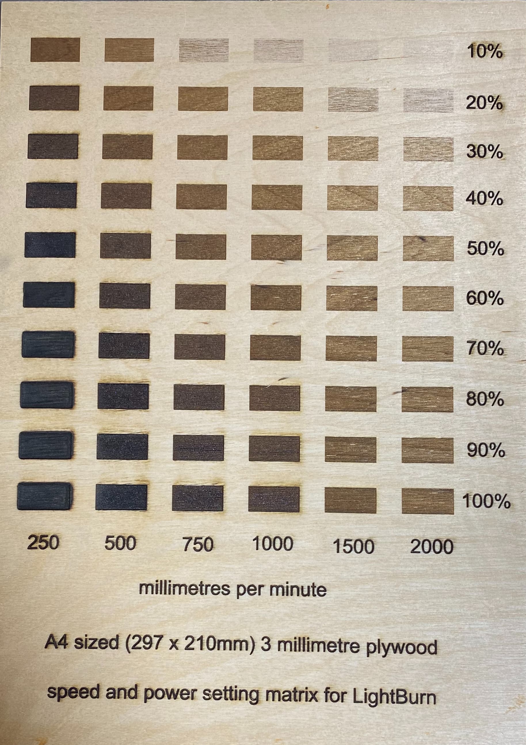
@alanan. The file linked is a power speed matrix I created for LightBurn. It is based upon an A4 sheet of paper (297 x 210mm) and I used this file for finding the best power and speed setting for 3mm plywood. None of the components are grouped so you can click on any of the cut colours and adjust the speed. Adjusting the power setting is done from the shape properties tab. Here you can change the power settings in any place within the matrix.
Ideally, you would only need to adjust the feed speed because the power runs at evenly spaced intervals from 10% up to 100%. I deliberately had the settings for speed very slow because they will show you at what point you will get soot stains for each material and also when the sharp edges become a little frazzled. This file is slow and will take about 3 hours to complete. The patches are 20 x 10mm in size which should give you a reasonable amount of stock to compare the finishes.
Note to @gwilki : This is a LightBurn legacy file (.lbrn). Could the file acceptance arrangements be updated to include LightBurn 2 files (.lbrn2) please? Thank you.
the cleanest file up close is the 20% power at 500mm/min. There is a slight indent of around 1/20th of a mm. If fine finish was really important, I would choose the 10% power patch at 500mm/min. This one has no indented plywood. I use these matrix patch tests on all stock materials which I have never used previously.
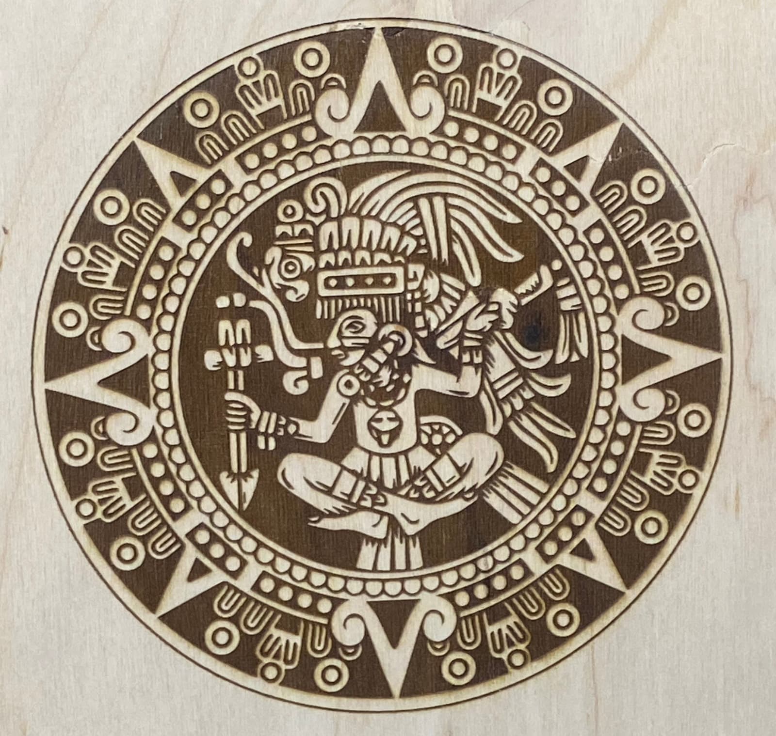
While showing some results of too slow a speed or too much power, I have a couple of files that demonstrate this very well. I was hoping to carve some sort of Aztec lookalike file that was not quite a calendar. Unless they are done at a large size, they can be very fussy. I suspect that toolpaths can be a nightmare with such busy illustrations.
The first image is my burning of the bitmap file in an effort to understand how it could look. I intend to carve it with parallel sides and insert lots of different woods and at least some brass and aluminium. The burn looks OK at first blush. Closer inspection reveals over burning. Take the cardinal points of the compass and if you examine the western point (9 o’clock) you will see that the bottom inside edge of the large triangle boundary is sharp and clean. The top edge is fuzzy indicating too much power was used or too slow a traversal speed was selected. Soot on the surface of the wood is yet another clue. Power was set to 40% and traversal speed was 1000mm/min.
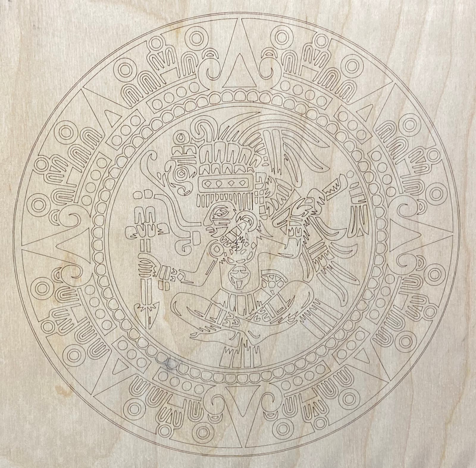
The next image is a look at the SVG outlines which would be used to create the toolpaths. It is a bit fussy looking and could stand some judicious editing to simplify the design. However the burn is very clean with no soot or over burned areas. Power was set to 10% and speed was 500mm/min on 3mm poor quality plywood.
@jepho Tks for all your examples. I didn’t mean to imply that I was looking for power charts. I have the files that LAHobbyGuy provides and have used them to burn examples on these wood species that we commonly use. So far, they are doing the trick.
Hi @alanan. Ah, that was my misreading of your post. Nevertheless, I managed to post a chart that may help other folk. The key is in graduating the power setting via the shape properties tab, which I did not think was especially obvious to the new users.