New Longmill Mk2 30 x 30 user. Setup and run first few test projects went pretty well. But I noticed the travel on the right side Y axis is not consistent with the left Y axis. Meaning If I bottom out/zero the y gantry to the top (where the two stepper motors are) and then jog the machine all the way back to the front, by the time the left side touches the end stop my right side still has 5mm left to travel before it bottoms out. The same thing happens if I bottom/zero it out at the front and jog the machine all the way back to the top I end up with a 5mm gap on the right side.
I have attempted to diagnose and correct the problem by checking the following:
Check the Delrin wheels to ensure that one side is not too tight
Check the anti backlash nuts for the same issue
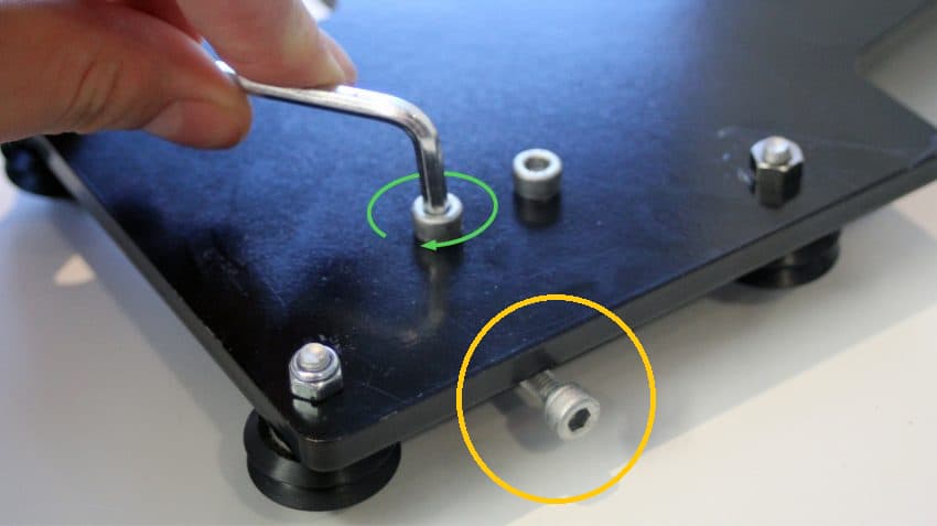
Check the coupler between the motor and check ACME nuts to the lead screw to make sure there is no slippage
Checked bench is level and long mill is square
Checked X gantry is square to the Y axis rails
Switched the wires on the Y motors to see if problem switches sides, checked the motor wiring to ensure it is firmly plugged in
Checked the dip switches on the controller to ensure set correctly, changing each dip and moving it back to correct position
Checked current setting on potentiometer on the driver is set correctly at 2 A
Checked lead screws to ensure smooth wand no bends.
Nothing I checked resolved the problem I was having. How ever when I replaced the leads screws, I must have replaced them back in the Mill on the opposite sides. Now when I jog the gantry from one end to the other my problem has switches to the other side. I changed the lead screws back over several times, each time the problems changes over to the opposite side. This has me believing the problem is one or both of the screw.
Is it posable the problem is the lead screw i.e. the pitch on one of the lead screws is at a slightly different pitch to the other causing the gantry on the one side to travel faster or slower than the opposite side. Has anybody else experienced this before. At this point I cant see that the problem is anything other than one of the lead screws. Any thoughts greatly appreciated.
@Andy-84SSM , I can’t fault your logic, but it seems odd that the lead screws are different. That said, 5mm in 30" is about a 0.66% difference which seems too much for me. When you swapped lead screws was it just the lead screws? Not the stepper motors, bearings, anti backlash blocks, etc.?
@Andy-84SSM - First of all welcome to the group Andy (since nobody else did, lol). Just a wild thought of a couple of things. 1st - are your couplers both pushed onto the motor shaft to the same position? 2nd - if 1 is correct then are both lead screws pushed all the way into the couplers? 3rd - if both 1 and 2 are correct how many millimeters are sticking out of the front feet with the acme nuts. I guess what I am trying to suggest is if there is an alignment issue between the 2 lead screws. I don’t even know if that’s possible but it seems to me it could be. Maybe Chris Thorogood can shed some light on the issue. He’s the engineer, not me. Just some suggestions.
Hey @Andy-84SSM, welcome to the forum. Good group of folks here for sure. Wish I had a solution for you, but will compliment you on your troubleshooting skills. Have you done a support ticket with Sienci? I am positive they will work with you to solve the issue.
Oh yea, if you would, please post your final solution here. That helps all the rest of us too.
I only swapped the lead screws over which results with the problem moving to the other side of the Y gantry.
I did change the motors over while trying to find what is causing the problem . everything stayed the same as it was before.
checked both motor and lead screws extend into the coupler the same on both side of the coupler 0n both Y axis,. also the measurement of both lead screws extending past the front feet is 16.79 mm on both sides. again both the same so no miss alignment that i can see.
Well, it is a puzzler. Sure sounds like a difference in lead screws. I’ve wracked my brain and, based on your experiments, I can’t come up with another solution. If you have a micrometer maybe you could make of physical measurement of the thread pitch on each screw and compare? Measure across as many threads as your micrometer will span to magnify any possible difference.
I have exactly the same situation with my Longmill 30 x 30 MK2. The right hand Y axis is slow in both directions. After utilizing the gSender calibration tool, I found out that the left X axis is too fast. Reading through Andy’s steps, I did do steps 1 through 6 and 9. It didn’t occur to me to do steps 7 + 8 after doing step 6. I don’t think it’s necessary. Correct me if I’m wrong.
I will patiently sit back and observe the fault-finding process.
@Andy-84SSM
It could be the adjustment bolts on the anti-backlash nuts. They might be adjusted differently ever so slightly, causing one side to hit the feet before the other one, giving the impression that one side is traveling further.
I will try adjusting the anti-backlash bolts. I’m not sure what you meant by “giving the impression one side is travelling further”. The left Y axis is definitely faster and hitting the feet about 1/4" sooner than the right hand side.
I should have said giving the impression one side is lagging behind.
Mine did the same when I first set it up but it was actually the M5-25mm bolts that were hitting the feet. One side was adjusted maybe a quarter turn more so the other side stuck further out a tiny bit. When that side hit, it stopped but the other side still had a bit of movement left.
I ended up switching out the M5-25mm bolts for a slightly shorter set so they didn’t stick out past the gantry any.
The son in law is having the same issue on the mk2 that I purchased for him. We have been trouble shooting the problem for a couple days now with no success. Also having consistency problems with the depth of the z axis.
We have checked everything we can think of, adjusted the backlash bolts, tensioned the acme screws. Adjusted the wheels. Swapped the motor wiring. Doubled checked everything for square. I’m at a lost and am doubting the consistency and ability of the machine to remain true. I have lost confidence in this machine after running it for 2 months now.
In this picture you can see where the z axis just decides to start cutting deeper after doing a rapid move to the next tool path.
I was discussing this with the son in law and I gave it much more thought overnight.
So, when the machine was built we had problems with gsender disconnecting from the machine. This caused all kinds of problems, including causing the z gantry to go full send into the spoilboard and the y axis to move erratic. On multiple occasions the machine slammed the end stops. This was caused by windows com port going into rest mode. I changed the settings so that the com ports never turn off and that cured the disconnect problem.
Having considered all moving parts in the system, it is my belief that the weak link and most likely culprit for the inconsistent travel is the plastic anti-backlash blocks. Since they may have been damaged from the force of the machine banging the end stops.
I forget if we got extras with the machine when it was shipped, but I will be tearing down the machine for the third time now and examining those backlash blocks.
All thing’s considered, process of elimination determines that if the couplers are secure, the axels are secure, stepper motors operating correctly, software is properly handing input from gsender, then it has to be the most simple of items.
A couple of small test runs have showed that the machine does not deviate that much in short distances. It’s only over greater distances of the y axis that it changes. The further the distance the more out of alignment it gets. Also it keeps going further and further out of alignment the more we run the machine. This points to a tolerance problem in the axle or the backlash block. Since I believe the stepper motors are accurate and most likely the acme axels are ok, it has to be the backlash blocks.
I’ll let you know what I find when the son in law tears it down tonight.
Hi Andy, I don’t have one of these machines (mine is a Shapeoko SO3) but I was curious about the issue you are having. Please take anything and everything I say with a very large pinch of salt.
You have checked everything very comprehensively.
It is not unknown for Delrin wheels to acquire a flat if they are too tight and slide rather than turn or where they sit for a long period of time with the gantry weight compressing them. On my machine they are tightened so that they just resist easy turning and need moderate pressure from one finger to turn them. This leaves them free to track the ‘V’ angle on either side of the extrusion… as closely as possible without binding.
The lead screw issue is very suggestive of a QA issue from the lead screw manufacturer. As the screws are machine produced, it is unlikely that they are both some way out of spec, though not impossible. I have seen them being sold in matched pairs which does suggest that differences can and do exist. When changing the screws side for side, are you also changing them end for end? It may be a question of ensuring that the start of the thread begins in the same place on each screw. The change in speed between the sides may be because one thread is biting sooner than the other and it will move the X rail quicker on one side than the other.
Have you tried slackening the backlash adjustment until it is not present? Then hand turning the lead screws until the X rail is square and at the place you want the travel to start from at both the front and the back. This will guarantee your alignment of the X rail on both Y rails. In terms of measurement, you can draw lines at the same distance from the feet on all four corners and use those to set up the correct position for the X rail and follow the appearance.
You will have to start with some assumptions like the build is actually square and that the stepper motors are driven identically and are not losing steps. The Delrin wheels can cause step loss if they are too tight. Having seen the illustrations for the Longmill, I would also be inclined to put an accurate square on the feet. That slow bend on them would have me considering if they are quite 90 degrees.
I would also want to to have the Y rails absolutely level to the base but with that foot arrangement, I would probably struggle to ensure that level and flat arrangement. Ideally, one would place the Y rail against the baseboard and screw the feet to it. You cannot do that when the feet are in situ. I accept that foot attached to a rail ought to be in the correct position but you would possibly not easily see a small difference in parallelism between the rail and the baseboard. I would opt to measure the distance from the bottom of the foot to the underside of the Y rail. I would then make a supporting board that was the precise thickness and just the width of the Y rails outer edges. I would align the Y rails with the outer edges of the supporting board and they would permit the feet to be screwed to the baseboard while allowing the rails to rest level at the correct height to the baseboard.
I don’t know if this is useful but as I stated, please take this with a very large pinch of salt.