@gwilki Thanks Grant. I think I will go with option 1. I like the idea of having the fire button near the laser too. Plus I won’t have to lengthen those wires. I may cut the wires and install quick release connectors but that would be all. That should eliminate any issues with voltage drop between the control box and the laser/fan. I will just have to make some type of platform for the controller to sit on while burning.
I, like you, can see where lightburn can do a lot more than vcarve can. I especially like the grayscale setting for photos. Makes it a lot easier to set up. I just need to get busy and experiment to learn how to adjust speeds and power to do what I want. Also, like you, had a little trouble understanding the video on how to set 0. I have a plaque I need to do for a friend who lost his wife a few weeks ago. I need to place an oval photo just a shade off center in a recessed oval on the material. It’s going to be tricky. I am definitely going to experiment with scrap first. Like you I’m a little slow but it will get done.
@Heyward43 I think you’ve talked me into keeping what I have H. The fire button really is important. I can make things more pretty by running the pwm cable and the power cable through the drag chain and putting plugs on them.
I’m keeping a log of power and speeds in LB, since the whole concept is foreign to me. I’d be interested as time goes on to hear what you come up with for successful projects. So far, I’m not doing any Z moves. I set the laser to 1.75" above the piece and leave it there. In time, I think that I’ll play with Z moves so that I can get ever more distinction between lights and darks.
This is what I have decided to do as well, extend the PWM wire and power cord through the drag chain with disconnects to be able to pull it off when making chips and dust.
I don’t really have a place to put the laser control module, so I am thinking about making the Andy designed router mount for the laser wider to accommodate the control module. It would stick out more to the front. Still a concept as I am not home til next week now. I know the control module has a couple of screw holes in it, probably M3’s. Pretty sure weight will not be an issue.
Going to keep a log as well of Lightburn settings for projects. I have that horrible CRS disease so that should be helpful.
I am intrigued by the new $49 VCarve laser addon, but do not currently own VCarve, so we will see.
@stevendq I was intrigued by the VCarve laser module until I saw that it will only run on the newest version of VCarve. Since that is not the version that I have, the total cost is not worth it to me when there are other, less expensive or free options. According to the JTech site, they worked with Vectric to develop the laser module, so I’m thinking that the post processor at least is the same.
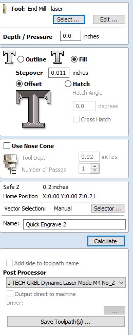
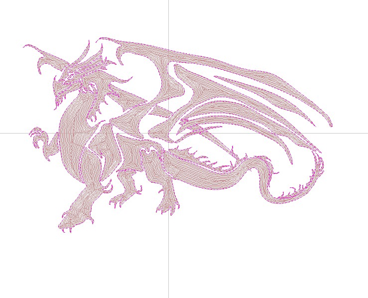
Guys, speaking of the JTech/Vectric pp. Grant, can you post/picture of your tool settings or the settings you used for the dragon. Also can we use the preview to see what it will look like? So far I can’t see anything of what it will look like. TIA
I used the quick engrave toolpath setting in VCP and there is no preview for it. However, I did two toolpaths, one fill and one outline. When you calculate, you get a pretty good idea of what you will burn. I’m attaching two screenshots, one using fill and one using outline.
So, in reality, you have an infinite number of settings to accomplish the same burn. In otherwords reducing speed (power) to 500 and feed to 250 mm/min should look the same the way as I see it. Oh well I just need to experiment like you guys did. See what I come up with too. Thank you again.
@Heyward43 I think that’s a fair statement, H. It took me 3 shots at a grey scale on hard maple to get what I wanted. At the same settings as the dragon, it was much too “burnt”. Then, I went too light by lowering the power and speeding up. Finally, as in the three bears, it was “just right”. Add in the distance from the lens to the piece and the possibilities are virtually endless.
Be interesting to plot peoples’ speeds, power, material and results - it’s probably a bit like ISO/f-stop/shutter speed/ambient light in photography, or throttle/aileron/airspeed/rate of ascent in a small plane, where you’ve got a system that requires 2 or 3 variables to be adjusted as a consequence of the one you want to change.
Some things to keep in mind when trying to compare. 1) Laser diodes come with different power ratings. 3, 5, 7 or 10 watts are common. Mine is supposed to be 10W+. These ratings aren’t exact guarantees, just targets. 2) The Chinese lasers are notorious for not meeting their rated power. 3) there are different lenses available. I have four different lenses. A G2 which has the highest transfer efficiency (i.e. lowest loss), but a very short focus range, A 3 element lens (higher loss, slightly longer focus range), a G7 and a G8. Both have long focus ranges and the G8 has loss almost as low as the G2, so that is what I’ve been using. 4) The last variable, that I can think of, if focus. Proper focus is important to maximize the laser power getting to the wood and to minimize the size of the point of light. Smallest point = highest resolution (and power). Since we have a Z-axis available I fix the focus ring on my laser and adjust the focus by using the Z-axis.
So, it’s ok to compare settings from other users with lasers of the same wattage to get starting points, but you will have create some simple test projects to experiment with to find speed and power settings that produce the results you like. You will have to do this for each material you plan to etch/engrave/cut. It’s not difficult. Just takes a little time.
@gwilki@SteveFossey@paullarson - So what we are all agreeing on is that NOBODY KNOWS! LOL, in my estimation feeds/speeds etc are so infinite there is no way what works for someone else will work for you. Take lots of notes for feeds, power, material type/color, etc. Love lasers.
Fair enough, but I guess I grew up on Machinery’s Handbook and a boss who beat me with it every time he heard my endmill chatter.
Trial and error is definitely required but a table of possibilities gives you a starting point on a manual milling machine. Can’t help wondering if the same applies to lasers and routers.
@SteveFossey - Please take what I posted as tongue-in-cheek. I’m sure there is a lot of consistent information concerning lasers and their operation. It just seems to me with so many manufactures of lasers it would be difficult to say do this and it will look like this. Especially in the cheaper quality lasers. I’m sure there are settings that will put you in the ballpark and you would be fairly lucky to hit it out of the ballpark, but it’s possible. I do plan on keeping a notebook of laser projects I undertake so I can try to make things look good consistently.
I read another article that dealt with setting the optimal distance from the laser to the material. The idea is that you set a ramp or wedge under the laser and burn a line from the bottom of the ramp to the top. The position on the ramp where the line is the narrowest is the best focal length for your laser and lens. I like the simplicity of it.
There is info out there about feeds and speeds that are good to reference. Just look for ones for your rated laser power. That will get you in the ball park.
Regarding focusing the company I bought my laser from (Endurance Lasers) provided me with a thin anodized aluminum plate the size of a credit card to focus with. You put it on the material surface you are trying to focus to and start adjusting the focus. On my laser the lens screws in and out and has a threaded locking ring so you can focus by doing this, but what I have done is adjust the lens to provide its longest focus and locked it in place and leave it alone and focus to a surface by adjusting Z height. So, with the aluminum plate on the surface and the laser turned on low I raise or lower the the laser watching for the laser point to get smaller and waiting for the point where the dot changes color and actually starts to sing! It’s kind of amazing. When the card is singing it’s in focus.
There is a lot of info on the Endurance Laser website.
@paullarson I’ll second the nod to the Endurance site. George, the owner, seems like a great guy, replying to emails on Sunday. His products are way out of my snack bracket, but many of his tips and videos are helping me with my cheapy.
Finally! Laser is quasi installed and working. Spent about 3 hours trying to figure out why it didn’t seem to be working. Seems I didn’t have it set up quite right. But figured it out. Just a heads up on the wiring. I placed the controller on a little platform attached to the Z motor bracket, just to the side of the drive belt. I used 8.5 feet of 18 gauge wire each for the power and PWM. No voltage drop on either one.
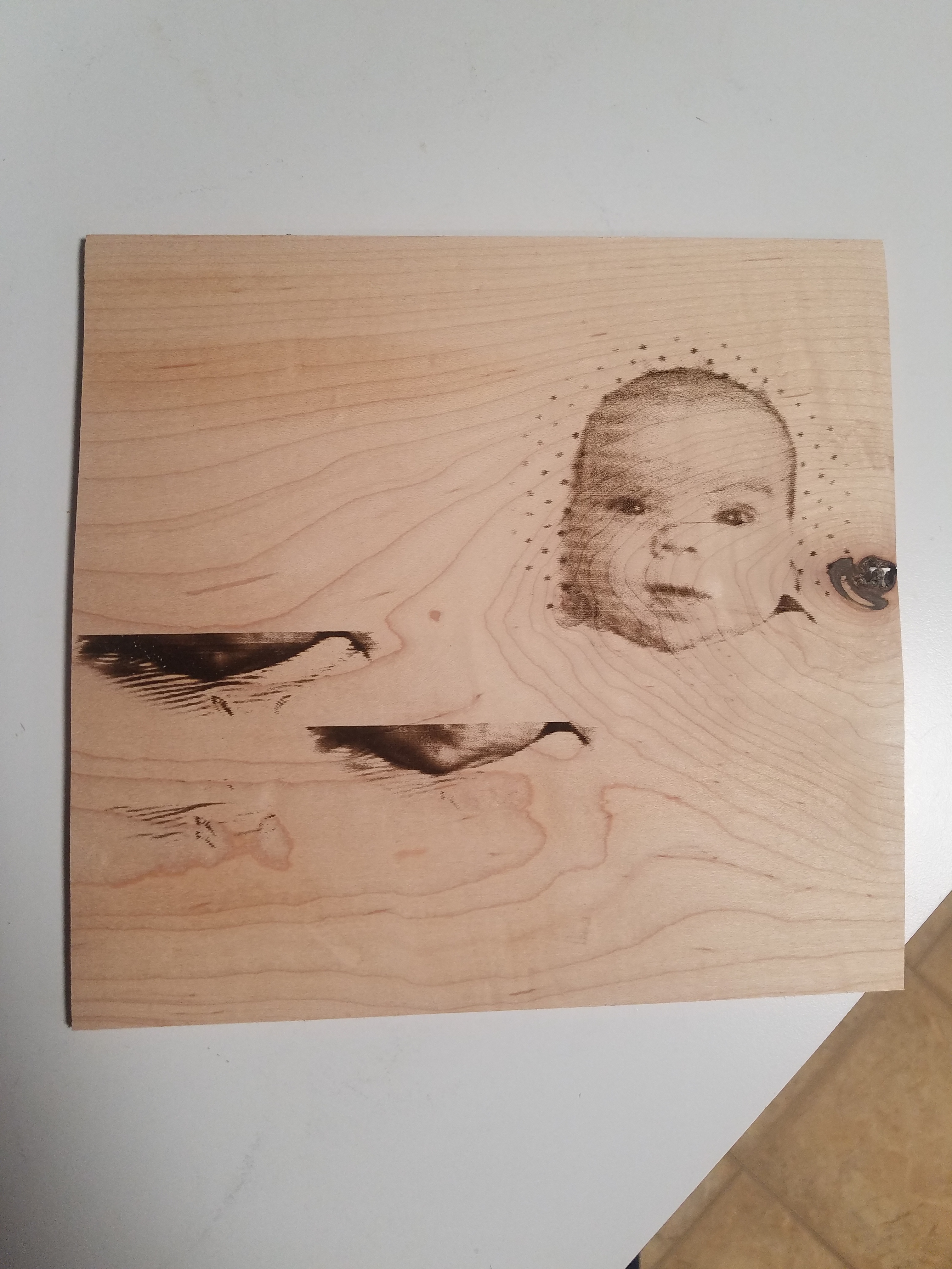
For software to create the image I downloaded the Vectric laser module (not the jtech post processor). You have to download one of the supported trial products to get it so I downloaded VCarve Desktop. You also have to test using one of their samples (as pictured). Usage is pretty simple if you already use Vectric products. They have added 2 new toolpath icons for the lasers. You also use the same post processor but the gcode is generated for the laser (actually for a spindle). Took 3 tries, as seen on the picture, to get a fairly decent result. First 2 tries to the left were way too dark so I cancelled them. The 3rd attempt was pretty good as pictured. The trial doesn’t come with VTransfer so couldn’t try direct to machine method. I saved the gcode and ran it with the LaserGRBL freebie software. The picture is roughly 3"x3" and took 2 hours and 57 minutes to burn. I hopefully can learn how to speed it up so it doesnt take so long. I know it’s slow but man the wait.
Now to go back and straighten out the wiring, wrap it and put it in the drag chain so it’s not cluttering up the table. I think I’m going to love this. I may have to take my old 3018 and rebuild and extend the frame so I can have a separate laser system so I don’t have to use the longmill. Oh well, another project.