LED strip odd behavior Altmill/SLB-EXT - RING works, RAIL is white

I made up a WS2812B RGB LED strip to connect to my AltMill SLB-EXT, with a capacitor at the strip as recommended. I also set up gSender’s SLB settings for 20 LEDs for both RING and RAIL, and connected a 5v/3A power supply to the RAIL power connector.

I used the Sienci SLB manual and Jim’s pdf for reference, and am using gSender 1.5.4

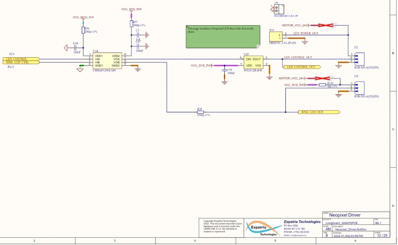
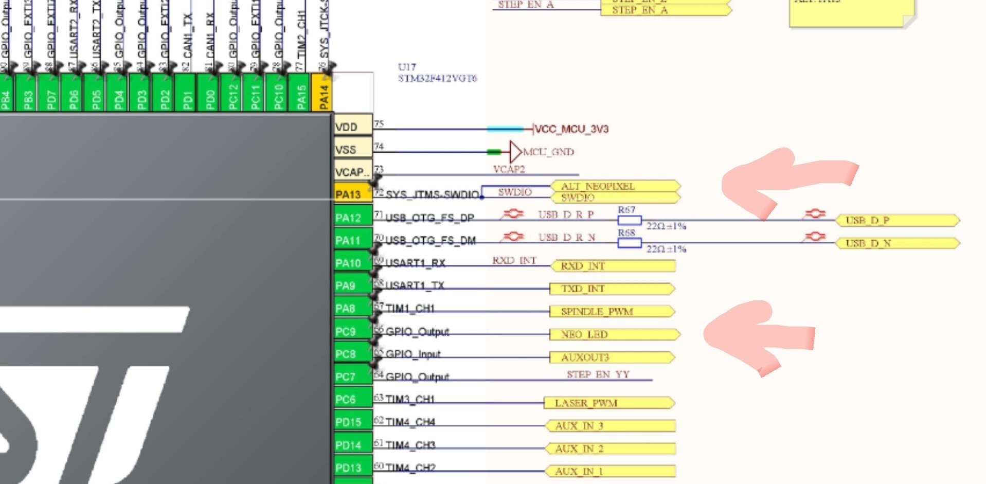
The Good: When the LED strip is connected to the RING connector, the strip works as expected - all 20 LEDs light up red, blue. green, white etc as the machine operates. I can change the gSender settings ($664 / ring) from 20 LEDs to other numbers, and after a hard reset, the quantity of correctly lit LEDs changes. The M356 P1 Q[0,1,2] commands dynamically change the behavior of the LEDs on the strip.

The Confused: On the RAIL connector, the same 20 LEDS all light up WHITE, and do not change color. I can adjust gSender’s settings ($665 / rail) to other numbers, and the quantity of white-lit LEDs follows. The M356 P0 Q[0,1,2] commands change the behavior of the onboard LED, but do not change the on/off/color of the LEDs on the strip.

My first thought was the power supply. I double checked the polarity on the RAIL plug and tried two different ones that put out a measured 5.1v filtered DC - with no change.

My second (on a whim…) was to try an RGBW strip instead of the RGB. On the RING chain, I got a cute mix of Red White and Blue because the 3-color data packets being sent by the SLB didn’t align with the 4-colors consumed by the LEDs, and when connected to RAIL, they were again all white.

The fact that the number of lit LEDs changes correctly when the $664/$665 settings are changed says to me that the power and data lines are connected, and the fact that the remaining LEDs on the strip stay OFF tells me that the data on the control pin isn’t being corrupted. The ONBOARD WS2812B behaves correctly, which says the firmware is at least reacting correctly.

Can anyone explain what I’m doing wrong - or what might be wrong with the strip, wiring or firmware, or suggest what to try?

@JPlocher Where is the reference to using a capacitor? FWIW, my rail ones work fine without a capacitor.

Adding a power supply filter capacitor across the 5v/gnd rails at the strip’s feed points is common in the 'duino/adafruit IoT world to counteract the current spikes caused by the possibly large changes in current flow that happen when all the LEDs change color or toggle on and off… They also help a bit with filtering ripples picked up in the (long) cables running from the uController to the LEDs. To be fair, adding it was my ā€œzero’th thoughtā€ after seeing the posts here about long cables… It didn’t change anything, either.

1 Like

@JPlocher Tks for the education. I think that, since mine are working, I’ll leave well enough alone. Good luck with yours.

Hi John,

Good write-up. You seem to have covered a lot of bases and there seems to not be a lot that you didn’t do to get to the bottom of it. I am wondering though… What is the behaviour of the status led on the slb?

When things don’t work as they should, I tend to look at the bare minimum and for what I know, the bare minimum of the SLB led-strip configuration is having the number of leds set to 1 (Activate SLB status light only.)

Does the led work as advertised without the led strip connected. How about when you connect the strip but still only adressing only the one led on the SLB?

Throughout all these tests, the onboard status LED operates correctly as expected.

The behavior I’m seeing could be explained by a firmware screw up, but since every other SLB-EXT has the same version, and others have this working, that seems extremely unlikely…

My next attempt will be to add a single neopixel on a completely different plug and wire to rule out more items, as well as pointing Sienci support at this thread.

Thanks for your input!

Although unlikely, something can be down at the software side. It might however be that something is scewed on the board. I looked at the github schematics (they actually worked after months of no reaction) and I found that the ring and strip have seperate data lines comming from the cpu. You could look at these components (IC14, IC28 and IC17-pc9) to see if all solder connections are looking solid.

The best route to take is indeed getting the siencitists involved.

I went to the schematic as well - and I have convinced myself that this isn’t a ā€œboard solderingā€ problem - the RAIL strip lights the correct number of LEDS when I change $665. For this to happen, the power and ground lines mist be correctly connected, and the data (led control out) must also be connected.

There may be a problem with the onboard LED though - or more correctly, the shift register/LED driver chip inside it. One of the common-on-the-intertubes suggestion when searching for ā€œWS2812B displays whiteā€ is that ā€œthe first LED on the strip might be badā€ - and the recommendation is to cut it off and start with the second one.

  • Corrupted data: The LED may remain lit but cannot properly process the incoming data. It could then send a corrupted or ā€œstuckā€ data signal to the next LEDs, causing them to flicker or display the wrong colors.
  • ā€œStuckā€ pixels: An LED may freeze on a specific color or brightness level and not respond to further data commands.

If that first chip had a ā€œstuckā€ problem, the rationale goes, it could be corrupting the content of the data packets it passes through without corrupting the overall packet format.

In this use case, that first LED is on the SLB and seems to be working correctly.

While I am an experienced electronics engineer, and have the tools to do board level rework on SMT components, I’d rather not void my warrenty quite yet by replacing that crowded and hard to reach NeoPixel :grinning_face:

1 Like

Debugging update: SUCCESS

The cable distance between the SLB-EXT RAIL terminal and the first LED in the WS2812B strip seems to be the culprit, as the behavior I’m seeing is very sensitive to differences.

I’ve repeated this experiment with both Microphone cable (three conductor cable with GND as shield braid) AND regular old 3-wire LED strip ribbon cable, and see the same results. My test rig is:

A) 1’ test cable
B) 6’8" (the length needed to route the cable out the front of the SLB enclosure, through the drag chain, to the bottom left of the X gantry)
C) 7’6" (as with B, but cable routed out of ā€œbackā€ of SLB enclosure)
D) 10’ (allows multiple routing options)
E) 12’ (what I used for the first post above)

  • All lengths work reliably on the RING connector
  • Only A and B work reliably on the RAIL connector
  • C works, but random LEDS have a different brightness/color
  • D and E light the correct number of LEDS, but only ALL WHITE.

Referring to the schematic (above in this thread), I suspect that the difference is the signal integrity and drive capability of the RING circuit versus the reliance on that of the onboard SLB status LED used in the RAIL circuit. If this is so, your milage may vary due to the manufacturing differences between WS2812B devices.

My next after-lunch experiment will be to put a single WS2812B LED in the middle of the cable as an inline amplifier to see if it makes a difference.

1 Like

do your shorter lights actually react and change color as they should?

I have boosters from my christmas light time that would reconstitute and clean up the signal I may try that with a line and see what I get as my rail leds just are white all the time with an occassional very brief I am done blink.

Yes they do. I haven’t had time to try the led-in-the-middle trick, and when I turn them off and move the spindle, some of the individual leds come back on with random colors…

Your repeater idea sounds similar, if it works, post here :nerd_face:

Jumping in on this as I am stuck with the same issue. Hooked mine up today, have not run the wires in the drag chain yet but figure I have 12-13’ of 22AWG between the SLB and the LED strip.

Looks like this was also identified here.

So I guess I will try to trim the length down and try again.

Considering this is a relatively short run (for LEDs), it seems like the data signal is weak out of the SLB.

I haven’t had time to patch in a test ā€œrepeater LEDā€, but after looking at the SLB schematic, where the only real difference is that the RAIL signal is driven through an onboard WS2812B chip first, there is weight behind the conclusion that WS2812B chips have a lower drive capacity than expected/desired :frowning:

Not that I have tested this extensively, or much at all, but here is what just ā€œworkedā€ with the AltMill at Idle.

I put a 1000uF (did not have a 100uF) capacitor across the + & - nearest to the LED strip on the X axis.
I put a 330 ohm resistor on the data line at the connector coming out of the SLB. (Polulu said 100-500)

This enabled me to use Q0, Q1, Q2 and visibly see the entire strip light up and respond to commands.
I entered M356 P0 Q0 and the hit the E-Stop and all 60 LEDs turned red.
Upon clearing the E-Stop, all returned to white.

Not sure of you have any of the components lying around but you might try this.

Also, not sure the capacitor was needed… I initially had the resistor near the LED strip and this resulted in various behaviors of the lights, some on some off (sometimes), rainbow colors, and more. When I moved it to the SLB side, then it worked.

Also - I did not trim my wires any but will before I solder this all up and finish installing. Meaning that I have at least 12’ of 22awg running with the above configuration.

2 Likes

I was wondering if I had gotten a faulty WS2812B LED as mine would also just stay white and doesn’t react to the changing status. I can get it to address the number of LEDs, but never any of the color changes. I stopped caring about it after a while but always thought it’d be nice to have. When I have some time I’ll test out the wire length to see if that does anything.

Can the RING connector even support 60 LEDs? thought it was only up to 40

Might have to give @whitewolf ā€˜s suggestions a try on the cap and resistor.

1 Like

I think the resistor is the key here… and that would simulate a LED or Load earlier in the wiring which I think helps keep the Signal clean.

I have gone ahead and trimmed the wire (about 10ā€ less), soldered in the resistor and capacitor, and run the wires in the drag chains.
I retested and so far still works - using a 5V 2A USB Phone charger.

I’m waiting on delivery of what will be the actual Power Supply (5V 3A supply w/DIN plug [not charger]) so I hope it doesn’t change how it works.

Ya that would make sense.

I’ll have to dig around to see if I can find a 1000uf cap, would you have used a 100uf cap if you had it on hand?

I assume you just put the cap across the + and - pads on the LED strip

and for the 330ohm resistor, you just spliced it inline of the data line but as close to the connector on the SLB-EXT.

If I can find a resistor and a cap…I can test this out as i have a 5V 3A PSU that’s on the machine currently.

Yeah, the recommendation was a 100uf cap so that should be enough.

And correct on the resistor as well. Anything from 100-500 and in-line on the data/signal line right out of the SLB.

Very interested if it helps you!

I’ve been meaning to update this but was locked out of the forum due to the certificate being expired…none of my devices could access the forum.

I reduced the cable length by about 2ft…I don’t know the actual length of the wire run, but there is no extra slack…but still no impact, the LEDs still only stayed white.

Added the 100uf cap to the +/- pads where the wire meets the LED and a 300ohm resistor inline of the data line. This worked for me. The LEDs are now able to change colors accordingly.

2 Likes

Awesome! Happy to hear that worked for you. I haven’t turned mine on since I installed and tested but am looking forward to the light show when I’m able to CNC again!