Let's make a tool table for manual tool change and auto zero based on selected tool

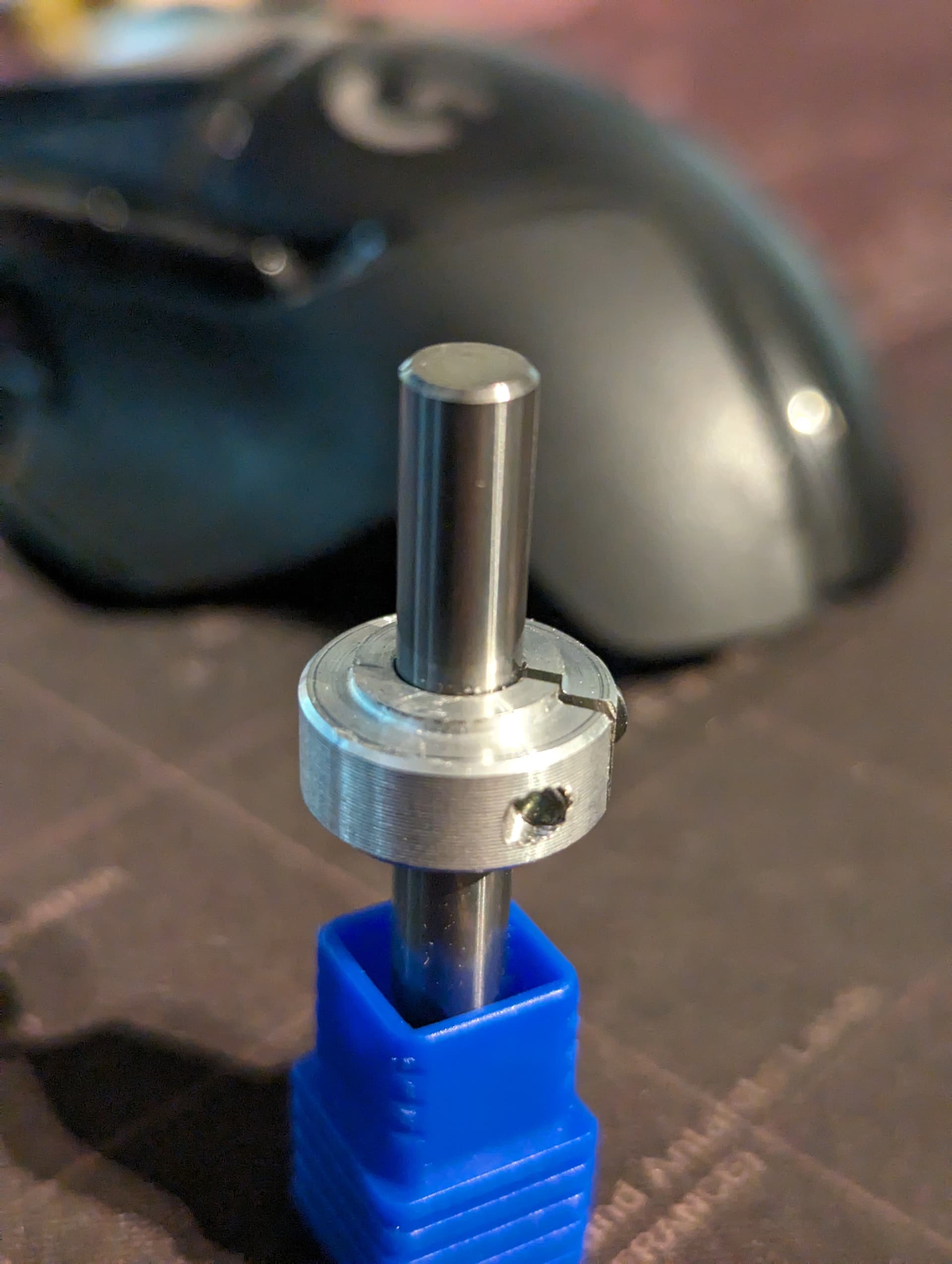
So, my idea i as follows, i have a probe that can do XYZ, and some tools. i know how long the probe is and i can measure all my tools and add the offsets of every tool based on the length of the probe.
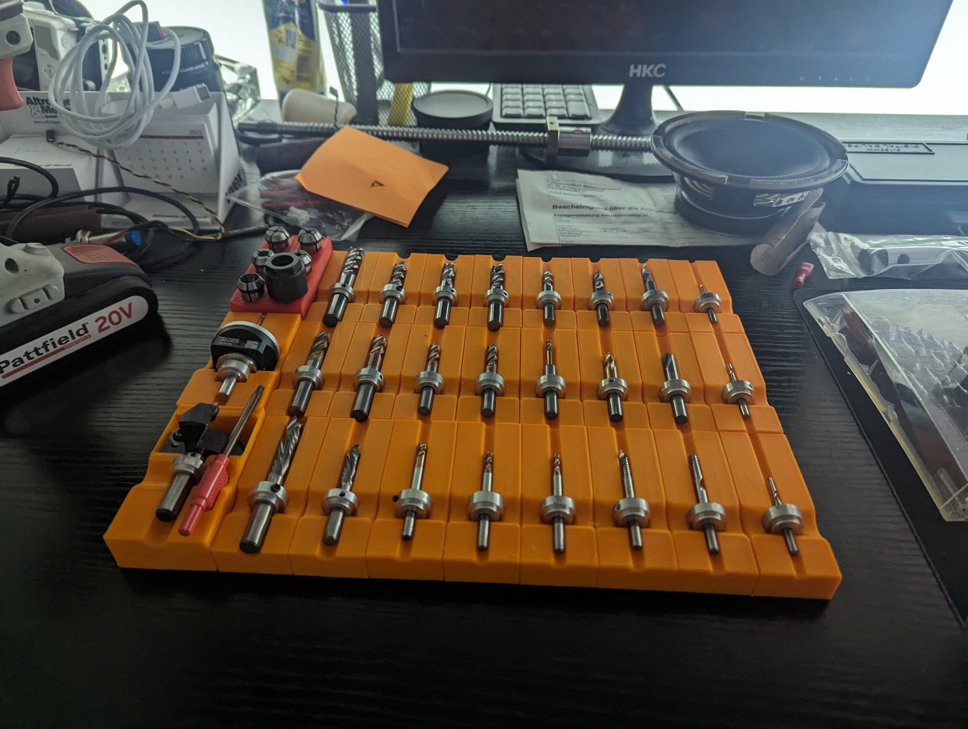
i added bellow a pdf file so you can take a look at all my tools i have, and how i do the math. but is it very simple,
i know my probe is 54.05mm long this is my tool number 1, now if in my project i have to use tool number 10 the length of the probe minus the length of tool number 10 give me an offset of 12.35mm , for now i do this manually where i send the machine to XYZ zero with no tool, the add minus 12.35mm and rezero the Z. but if i need to change the tool to let’s say tool number 4 what i need to do is remove tool number 10, send the machine to XYZ Zero apply tool number 10 plus 12.35mm and then apply tool number 4 minus 25.05mm and rezero Z again
it would be very helpful if someone could just code a script where the tool offset just changes based on the selected tool. i know it’s not hard, but i can’t code, so if someone has the knowledge and what’s to try …
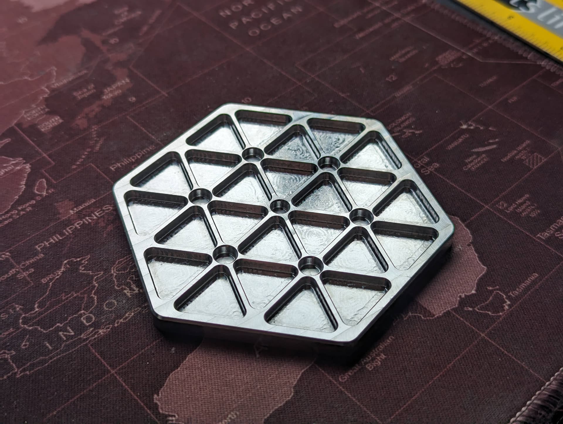
how do i know this works very well? well i just made something using this , see image bellow

i know it’s a bit of a mess on how i numbered the tools, but it’s how it is in fusion, i will change that so each tool has a unique number

Tools Offset Table - Tabellenblatt1.pdf (55.7 KB)

Btw i forgot to mention that every tool has a stop on it like shown bellow


@iuliancalin An interesting challenge. One question. You say that the offset between your probe and tool 10 is 12.35mm. However, in your chart, the probe is 54.05mm and tool 10 is 40.9 for an offset of 13.15mm. The chart shows the offset as 12.35 but then shows 0.8 in an unidentified column. (There is nothing in this column for most of the tools.) What is this additional offset?

You seem to be asking for someone to make you some sort of macro or script that will move in Z, then reset Z0 to accommodate your new tool length. Correct? I am asking because this request, if I have it correct, is not strictly related to gSender and there may be a better category for your topic.

the aditional 0.8 is there because i change collets from 6 on the probe to 8 on the tool. i did that after i did a manual check on the tools using paper. i do need to fix that and find a way to measure all the tools again and have them perfectly offset using the spindel itself, but i kinda have a brain lock for now.
if you look at the math you can see that the 0.8 is not on every tool that has the 8mm colet

i was sure i forgot something, in my mind i was thinking of integrating a tool table in gsender itself, no macro. i’ve seen something similar in mach3
and no, i don’t mean to move the Z down or up, but instead change the value of Z axis without moving

to get you a better explanation would be , i probe to find Z, Z goes up 20mm above Z zero then using the program i select the next tool, tool 10, now because i changed the tool in Gsender the Z value changes to 32.35mm because the tool is shorter then the probe
does that make sense?

move this post if it’s in the wrong topic, sorry about that

=D14-D2+F14 this is the math in my chart
D14 is the tool
D2 is the probe
F14 is the added plus for measurement error

@iuliancalin Since you are asking Sienci to create a tool table for gSender, I’ll leave the topic where it is.

1 Like

If these weren’t turning at 18K rpm, I’d say they were alright.

1 Like

Agree with @CrookedWoodTex here. Be careful running an unbalanced collar like that on an endmill. That’ll tear a hole in you if part flies off.

That said, Grbl is not set up for tool tables like that. You can apply dynamic tool length offsets, but I find it simpler to just offset the Z with a G10L20.

Hi, I read some of the responses and liked the idea…
But… thinking about it now why not use code block at tool change? There’s an option on what to do before a tool change and then what to do after the change.
So if before tool change send machine to a position to replace the the tool and then either move to a location for tool resetting/touch plate
Or maybe the tool change location is directly over your touch plate

I’ve tested it and it’s totally fine, the only one that made some problems was a 2.5mm 1 flute endmill, other then that it was fine. Also the spindle speed was 29000rpm.
Also, there is the possibility to remove the stop after the endmill is in the colet, and put back before removing it.

Sure, a touch plate can be used, but, from my two year experience in doing tool change and using a touch plate, it’s not a clean solution. The thing is, if I set Z zero on top of the material I can’t use the same area to zero another tool. Also, I don’t understand the bit setter thing to set the endmill height after the tool change. I’ve seen some videos but it’s very confusing.

This is what I’m struggling with, I don’t understand the code :confused:

So, you’ve defied physics and created a spinning object that does not wobble at 29K rpm? Which possibly means that you have completely spin balanced those collar/bit combos?

Not trying to poke you without reason. Just trying to put some of my experience out there.

I’ve learned that no one can give advice. However, anyone can take it. :smiley:

so no one want’s to try it, fine, i just had a new idea
let’s say an ER collet, but it’s uncut and undersized, and you have to heat it up to insert the tool. i know it’s very stupid, but i love it :face_with_hand_over_mouth:

1 Like

Tool change Z-probing thoughts

Settings/Probing
assume you have a .875 height touch plate/probe block.
assume you have material to work on that’s 1/4" height

step 1-go to settings probe and enter probe/plate height of .875(or what ever yours is)

step 2- on the Z retract enter the amount it would take to get to z=1" (so touch plate/probe height + z retract=1")

step 3- place you stock on you machine table

step 4 --insert tool into spindle and tighten

step 5-place touch plate/probe on top of spoiler board and not on your work.

step 6-jog machine over your touch plate/probe for z-probing

step 7-probe the Z-axis, once done the Z-axis should read Z=1"(this is the distance from tool tip to spoiler board)

step 8- remove probe

step 9- move Z down so that Z reads Z.250 (this is now the height of your material)

step 10-Zero your Z axis-using mouse, or using the console G10 L20 Z0, or G92 Z0 ( Z now = 0)

step 11-jog Z up above your material to a safe height…

Done

you still need to do your normal routine for setting X and Y

This should work for any tool length

I’m no expert but this doesn’t seem so bad…

so normally the probing is done on top of the material,

but sometimes it gets machined away and you loose the ability of resetting at that height

this procedure eliminates that problem because your starting out from the top of your spoiler board or bottom of your material to be machined
so you can always reference from anywhere on your spoiler board as long as it’s flat.
if it’s not flat, use the same location.
it sounds like allot but it’s what’s already being done in most cases, but maybe just a few things deferent.
when a tool change comes up, just steps 4 to 11 need to be executed
you can also tell machine what to do before a tool change ,
so if the sender encounters a tool change you can tell it to move to a location of your choosing for tool changing…
Just some thoughts
VicF

This seems like a lot of steps to zero at the top of the material to me. I’m not sure if you use this method or if your just ‘spitballing’.

My thinking if you are using a method like this is that you might be better off just setting Z=0 at the spoil board surface and setting your CAD/CAM software to match. I do this a lot and see a couple of advantages. First it’s really easy to not mark up your spoil board when doing through cuts because if Z=0 at the surface of the spoil board and you don’t cut below zero then you don’t mark up the spoil board very much. The other thing I find beneficial is to bring my material to an exact thickness. For example if my stock is just over 0.75" I will do a surfacing pass to bring the work area to 0.75" and then I have an accurate reference to both the top and bottom of the stock. This allows cuts on the surface to be the correct depth and get a nice perimeter cut that doesn’t ruin my spoil board.

You can get the same results from the top of the material if you are really accurate in measuring the thickness of your stock and the stock doesn’t vary in thickness.

I did take me a couple of projects to get used to thinking about things being referenced from the bottom instead of the top but I really like it now.

Just some food for thought and may your projects go well regardless of which method you zero with. :smile:

1 Like

It seems like allot of steps but really not, just my way of explaining it.
And you are right about just using the spoiler board as zero, you will save a couple of steps
But I think most people prefer to use the top of the material as zero,
I could be wrong😀

1 Like

In my case, I always know the material thickness so there’s no difference between Z-zeroing on top or bottom. It is so much more convenient to Z-zero to the bottom.

If I’m doing some small vcarve text, I’ll use the top Z-zero method just to be sure the small text depths are cut right. Remembering to recalc the toolpath for that change is somewhat of a challenge, though. :smiley:

this is the exact thing i’m trying to avoid, and here you are recommending it :smiling_face_with_tear: