I have a strange thing happening in what i can only describe as a measurement issue.
Ok, let me try and explain…
In Vcarve, I’ll set up my project, ex:
Using MDF sheet that measures
(W)614mm x (H)625mm
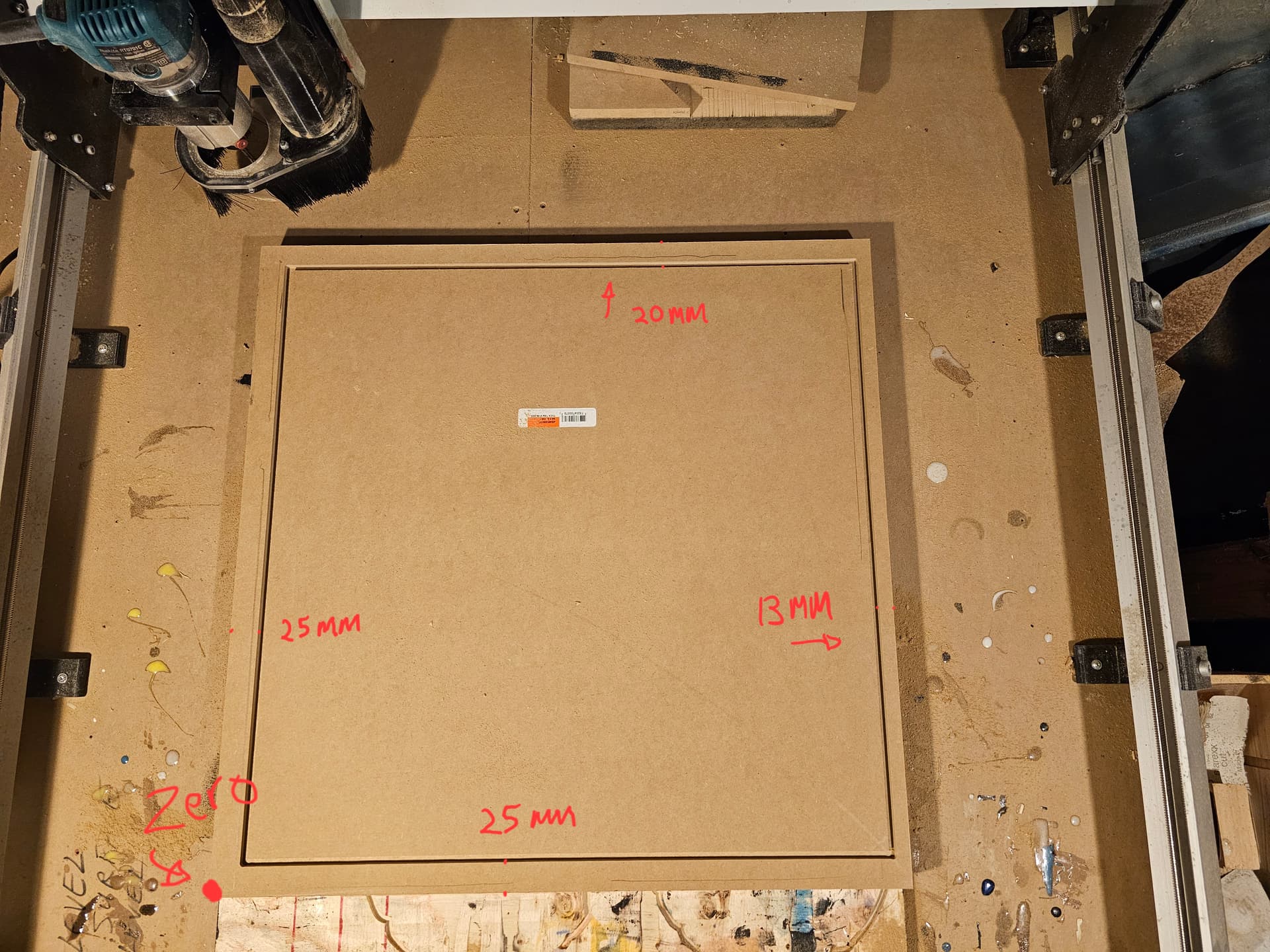
I’ll design my project and set my tool path (pocket) that creates a 20mm boarder around the entire piece so i can resin pour into it and carve out my design.
Everything looks good, I send it to gSender and when it cuts out the pocket, the top of the pocket is way too close to the top edge.
So, I checked my piece measurements, (their fine) inputted then into V carve correctly,
But then I ran my machine around the piece in gSender (to confirm the measurements)
and it comes up not correct with my original measurement.
I’ve calibrated, everything is fine. Not sure what is going on here.
@RicP I’ve just opened your file. In your first post, you said that your material size is 614 x615. In your file, the material size you entered is 614x609. In your latest post, you say that your profile is 563 x 552. I assume that is rectangle that you measured with a good tape, yes?
The rectangle in you file measures 563.95 x 559.206.
With respect, your measurements are all over the map.
Since you are setting your XY0 at the left front corner, your rectangle will not be centred on the actual material if you have entered a material size that is not the actual size of the material. VCarve will show it centred because it assumes that you have entered the correct material size.
You need to either set the material size to the correct size or set your XY0 to the centre of the material.
Let me explain, regarding the measurements, the first post 614 x 625 was a hypothetical number I was using to reference a rectangle, I was really trying to convey more that I was wanting to put a 20mm boarder around the piece. Which I did later change to 25mm on the design. ( that’s on me, I didn’t expect that someone would want the actual measurements of the piece, lesson learned. )
In the post above, the one I ask if you want the measurements from Vcarve… I posted the file measurements, that you just confirmed.
563.7mm
559mm
The post where I actual measured the physical material profile, the measurement was 563mm x 552mm and not centered.
This is the issue I’m having, the discrepancy between the software measurements and the machines actual cuts and centering.
Honestly, I don’t think my measurements are that much off.
I’ve had my CNC for around a year and cut several projects without an issue, the project I just finished before this one was a similar piece of MDF ( approximately same measurements ) with a different design and everything cut without incident. I’ll try and set my zero in the centre and see if that fixes it. Thanks for your help and patience.
@RicP Understood. To be clear, I was not saying that the only way to achieve your objective is to set XY0 in the centre. Doing that, then running a profile/cutout pass at the end of the project will ensure that your project details are centred on the final material.
Doing that also reduces issues with the actual starting dimensions of the material not being spot on.
If you prefer to set XY0 on a corner, using the touchplate, for example, and if your final toolpath will not be a profile toolpath that cuts through the material, it is critical that your actual material dimensions and those that you enter into VCarve are the same. If your final toolpath is a profile through cut, and depending somewhat on your project, it really is not critical, as your final piece will be centred in the cutout material.
As Promised… I found out what the problem was from a tech at Sienci.
In the firmware settings the stepper motors travel resolution (default 200 on XYZ) were off, he seems to think this may have occurred during an XY squaring operation, seeing I’ve never tampered with anything in this area. As of now, the machine seems to be working true.