_Michael's Dovetail Guide

This a guide on how I make dovetail joints on my LongMill. I’m posting it so I don’t forget how to do it and to help others. Even if you have VCarve Pro I think my way offers more freedom to do different sized tails or odd spacing etc. that I don’t think the gadget offers.

I will be using Vectric VCarve Desktop but my method should be applicable to other software and machines as long as you have a way to mount boards vertically.

First off so we are the same page with terminology here are the parts of a dovetail joint.
00 Parts of a Dovetail

I design the tails and sockets and then the pins. So I have two sheets in Vectric and the stock is the same size for both, at least from the end view of the boards. I’m going to use some MDF scrap I had laying around. It is 100mm wide, 19.6mm thick and the length doesn’t really matter as long as we can clamp it.

I will be using a 0.75" (19.05mm) 14 degree dovetail bit and an 0.125" (3.175mm) end mill. The cutting height of both bits needs to be greater than the stock thickness.

So here is the job setup in Vectric. Notice that the thickness of the stock becomes the height and the length becomes the thickness because we are looking at the end of the board.

The strategy for making the tails tool path is to make a long continuous vector that is the path I want the bit to travel along and then use a profile tool path, on the line, with a cut depth the thickness of the stock in one pass.

This is my layout for the tails and sockets. I have placed guide lines that represent the spacing of the tails and sockets 19.6mm, the thickness of our stock, below the surface. In other words the narrowest part of the tails and the widest part of the sockets. I have chosen to make two different tail sizes and two different socket sizes because I can!

Because I will be using many guide lines, and it can get confusing I make some rectangles that represent the area to remove. Notice that I extended them of the stock by more than half the bit width. That’s just so I can snap a guide there when I need it.

The next step is some more guide lines! The inner guide lines are half the bit width away from where we want the cuts to stop and the outer two are greater than half the bit width away from the stock.

After that I need, you guessed it, some more guide lines. These guide lines are like the passes in a normal carve taking off more material with each line.

Next I make the “tails tool path vector”. It starts at the lower left moving up and down each of the guide lines on the left. Then after it exits the stock it goes to the middle of the center socket and goes through the stock in a spiral pattern until all the center guides are used. Then it goes to the far right and works it way back to the left until all the right guides are used. When it does the center socket it will do a full bit width and depth cut so I need to use a slow feed rate. If you wanted you could use an end mill to clear first but you have to remember that the sockets narrow towards the top so you can’t clear the whole width. You can use some trigonometry to calculate the width at the surface if you want to make a roughing pass.

Now I am ready to make the tool path for the tails but first I need to set up my bit. Vectric doesn’t have a dovetail bit so I use the end mill tool type. The important settings are the diameter, pass depth and feed rate. The pass depth needs to be greater than the depth of cut so that Vectric will do it in one pass. The stepover doesn’t matter, that’s what all those guide lines were for. I used a very slow feed rate of 5mm/sec. That’s about 1" in 5 seconds for the metrically impaired. :slight_smile:

Now I’m finally ready to make the tails tool path. Notice that it looks like a box joint because Vectric thinks it has an end mill.

Now I can move onto the pins which are a little easier. The strategy for making the pins is to pocket out the areas between them.

I start by moving or copying the rectangles from the tails sheet to the pins sheet.

The guide lines for making the pocket vectors. Notice that the vertical ones are moved into the rectangles slightly. This is the fit tolerance, I moved the guides into the rectangles by 0.15mm and that gave a good tight fit. The horizontal guides are 3mm off the stock. They need to be off the stock by at least half the end mill diameter.

Now I can start to lay out the pocket vectors. I don’t know the width of the pocket 3mm of the stock, I only know it at the edge of the stock so that’s where I start my vectors. The dovetail bit is 14 degrees so I make the vectors 14 degrees from vertical, that’s 76 degrees. I also throw down some vectors for the top and bottom of the pockets.

After using the extend vector tool and interactive trim I have the pocket vectors.

Then I can make the pins tool path and preview it. Because it uses an end mill the preview looks correct.

Now it’s time to carve! Unfortunately the MDF tore out quite a bit on the tails carve. I wonder if taping the ends would help with this. I’m open to suggestions on how to reduce tear/chip out with MDF and wood when milling the end grain.

The pins is much better.

The tear out makes it look bad but the fit is tight.

So that’s how to make some dovetails on your CNC! If you have some time and patience you don’t need a Vectric Gadget or software beyond what you probably have if your a CNC’r.

The technique of just drawing a vector of where you want the bit to go and back, using the profile tool path at full depth can also be used for keyhole bits. Make some keyholes and T-tracks!

Thank you for the somewhat long read if your still hear! With a little luck and a lot of sanding you might make a joint thats half decent!

Dovetail Guide.crv (788.5 KB)

_Michael

8 Likes

@_Michael can you share a bit about your vertical clamping setup? I have been considering options for that, but never really felt comfortable with my ideas.

Great work and great writeup, thanks!

The clamping system is pretty simple and holds surprisingly well.

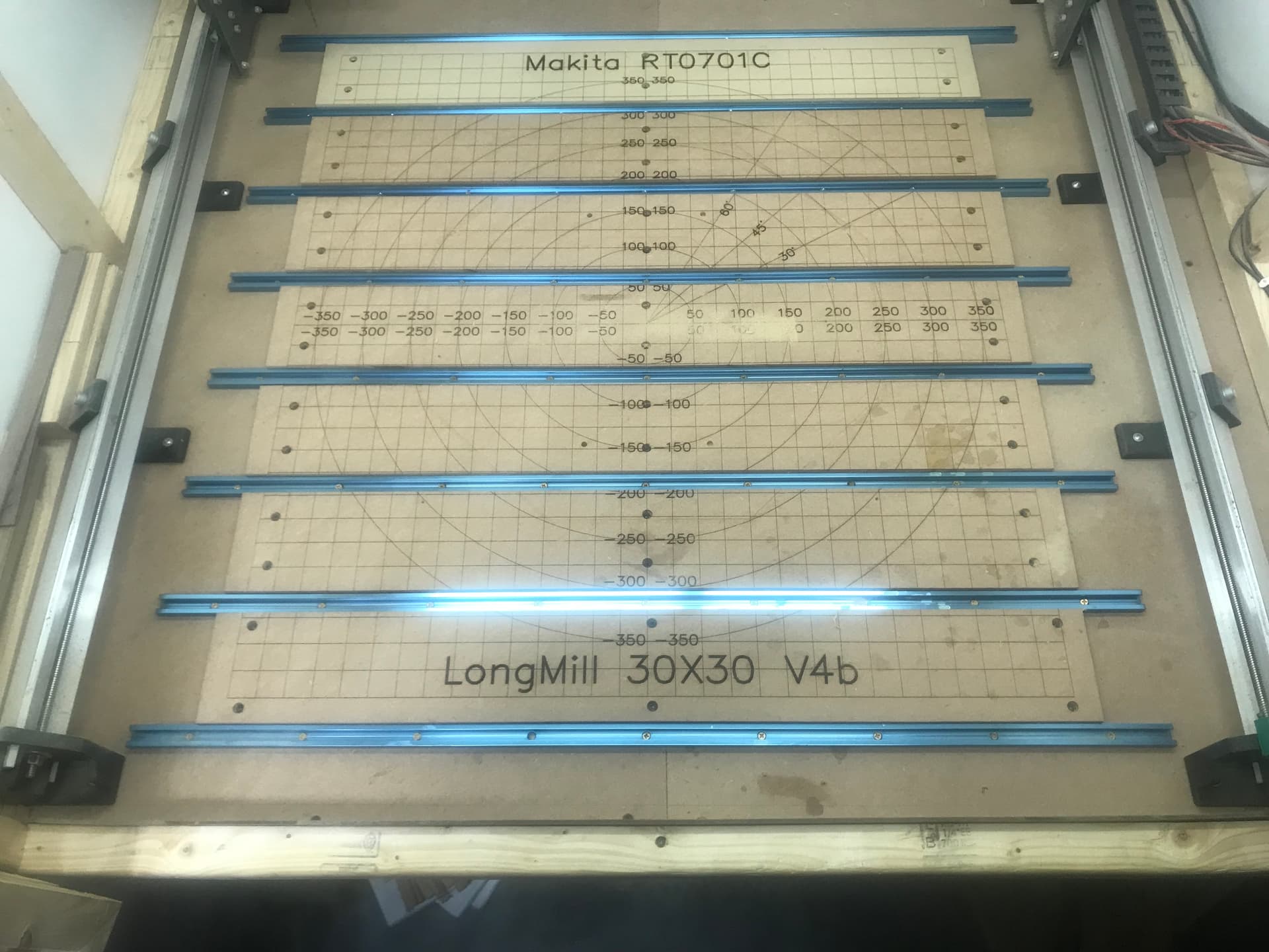
Here is the way my spoil boards usually look.

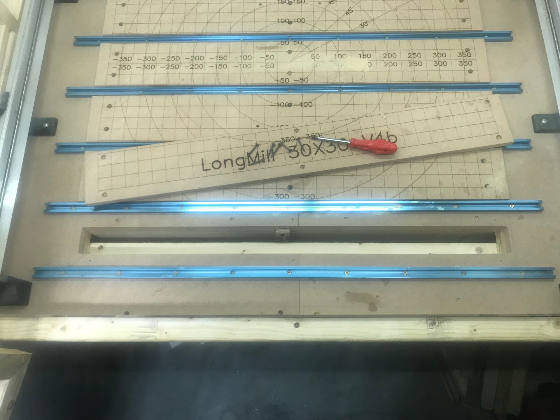
And for vertical I can remove the first section exposing a slot that I cut using the LongMill. You can see that I have a layer of 3/4" MDF and a layer of 3/4 plywood under that for my table top. The framing is all 2’x4’s. I had to put the router mount in the lower holes to reach when cutting the slot.

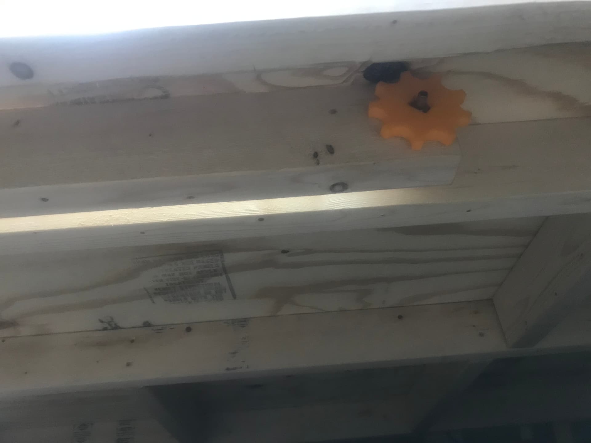
Next is under the table looking at the right side of a homemade Moxon vice. You turn the nobs and squeeze the stock between two 2’x4’s. The back of the Moxon vice, which doubles as a cross member was installed after the slot was cut so I could square everything up the best I could.

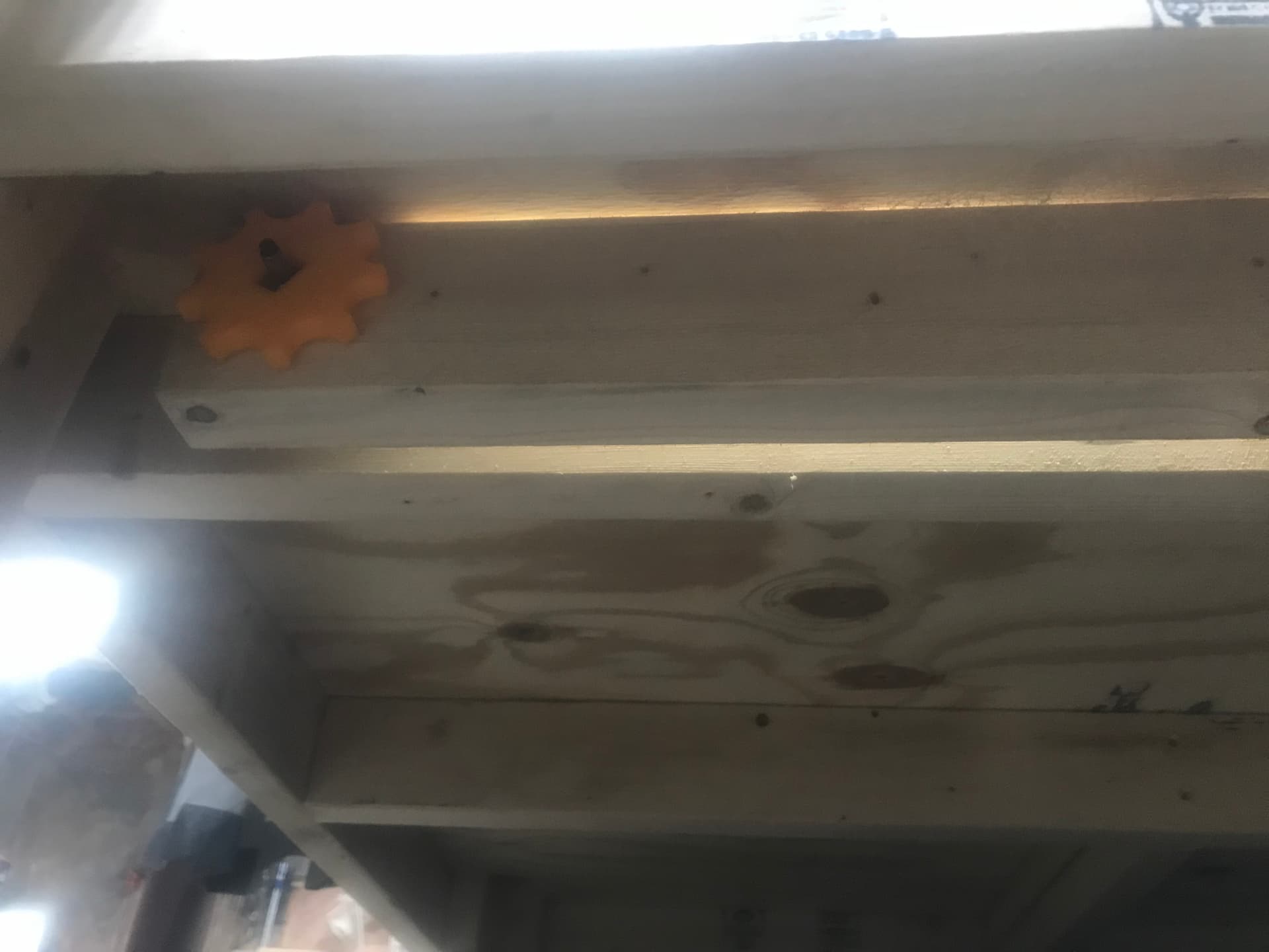
The left side of the Moxon vice for completeness.

And here it is clamping a board, the little vertical jig is set to vertical, or thereabouts.

The clamping system existed in my head before I started the table and dictated the horizontal spoil board pieces and some of the framing design. I haven’t been a woodworker for long and dovetails were pretty high on my list of things I wanted to be able to do. Something about them says quality, at least to me.

1 Like

Fantastic, thank you for sharing.

@_Michael Great post Michael Thanks much.

Michael,

Excellent description. I have Vcarve Desktop, so I can’t load gadgets.

Would you mind making a PDF document and posting a link to it? I would like to put it on my PC and print it for easy reference.

Thank you,

Roland

@R.Portman I’m glad you found my guide useful. As requested here is a PDF of the OP.
michaels-dovetail-guide.pdf (886.3 KB)

2 Likes

I should really take some pics of my moxon vise setup to add to this. I’ve yet to end cut anything but it was a pretty easy solution to vertical mounting.

1 Like

You should, my vice is just a hunk of 2x4 and some bolts that were kicking around the shop. I really did not put any effort into making mine look nice or anything. The thing is, it works so well I’ve never taken any time to improve upon it.


I made my table with a 5x24 cutout on the end. The vise was built in there and topped with MDF to match the spoil board. When closed, it’s usable table space. Accommodates up to 1.5" of board. If I were to do it again I would have gone a little deeper.

I reckon it bears mentioning that the vise jaws are 2" laminated ash. The stationary jaw is under the main spoil board.

3 Likes

Thanks for this post! I am a newbie so it’s beyond what I can do
for now. I am inspired to try this once I have some experience, so I will save your pdf plans.
I also love your spoil board. Do you have a link to a file for that?

The spoil board grid was done with my laser. It is centered on the spoil board. If you have the sensors and can home your machine, I suggest writing down the machine coordinates of the center position as well as saving them to a workspace or making a macro in gSender. That way you can always get your machine centered quickly.

Here is my spoil board graphic, in crv and svg format. Vectric Desktop let me create a project bigger than 24"x24". I’m assuming it just won’t create the G-Code for such a large project. I exported the svg and used LightBurn to burn it. I just designed in VCarve because I’m more familiar with it.

SpoilboardLaser

SpoilboardLaser.crv (525.5 KB)

EDIT: I forgot it would display the image, the just right click and “Save Image As” to get the SVG file.

EDIT2: Now that you have made a pretty spoil board, watch the following to learn how to not ruin it.

1 Like

Thanks, Michael. That is insanely cool, and I may need to borrow your grid design! I’m also very intrigued by your Moxon vise. I’d never heard of one before, but I can already see uses for it in terms of what I’d like to do, especially the option to profile surfaces that otherwise are at the mercy of the verticality of CNC. For example, if I want to angle the top surface of a guitar headstock 10 degrees, no problem. But when I carve the profile of the headstock, the tip will be perfectly vertical, and therefore “out of square” with the angle of the headstock. Not a big deal. A lot of builders (even big manufacturers) do that. But I can see your rig as a means to square up the top surface with its edge surface. Super impressed!

1 Like

Also, the dovetails are really gorgeous. I started reading the thread from the link you provided, but then backed up for more context.
My whole re-entry into woodworking, after like 40 years (back when I was a high-school woodshop geek), literally involved buying a Makita router and a rudimentary bit set. The intent was to buy a kit bass and modify it, but I had no surface, no station, no place to do it.
So, I took this old Ikea rolling cabinet that was going to seed in the garage, and decided to convert it to a “bass station.”
First order of business was to cut a grid of clamp slots using a dovetail bit. Not the complex and seamless stuff you’re doing; just a means to run some channels to use for MicroJig clamps.
The initial attempt was a minor disaster, but I recalibrated and ended up with a truly useful grid of slots to clamp down stuff. I use the hell out of that table still. I even added a side piece of ply, with the same dovetail channels, to do vertical stuff.
All of which is to say: I totally GET your interest in the Almighty Dovetail.
For me, it was kind of a “Gateway Drug” back into woodworking!
Cheers!

1 Like

I finally got a chance to mock up and test these dovetails and I love your process, Michael! I did back them with sacrificial material to limit tearout and i only cut a test set (I have a set of night stands I need to build at some point with drawers) but the results were great! You’ve saved me a lot of work!

2 Likes

Brilliant! I didn’t think of that to help with tearout.

I love this table setup and t-track waste board you’ve got going. I just bought the 48x30, it doesn’t look like the table and files you have would translate over to that size. Any chance you’ve moved up in size and recreated this setup?

-Tanner

I still have the 30x30 but I made up something for you.
Spoilboard48x30

I left out the circles and angles as I have never used them. I am also including the VCarve files, both before and after the text was converted to curves. Should give you a good starting place if you want to modify them. The dimensions were my best guess, I left the Y the same and added the same amount of ‘extra X’ but started with 48" instead of 30". The ‘extra X’ is because unlike most manufacturers you get more than advertised with Sienci.
SpoilboardText48x30.crv (727.5 KB)
SpoilboardCurves48x30.crv (584 KB)

NOTE: If you plan on using a laser to put this on your spoil board you will most likely need to figure out a way to mount the laser where the router is supposed to be mounted. Otherwise the laser may not be able to reach the full area that the router can.

NOTE2: When building your table there probably isn’t any reason to make the slot as wide as I did. You only need to make it large enough for what you want to work on plus a couple of inches. I have never even come close to needing the full width of the slot I made. I do still like the way I hid it though.

2 Likes

Thank you very much. I appreciate you taking the time to make that!

Also, for the clamp slot you built into your table, how did you get a perfectly straight surface running the x-axis with having to cut through the MDF that is on top of the Plywood that is then squared up to the 2x4 underneath it? I know if I tried that it would be a mess.