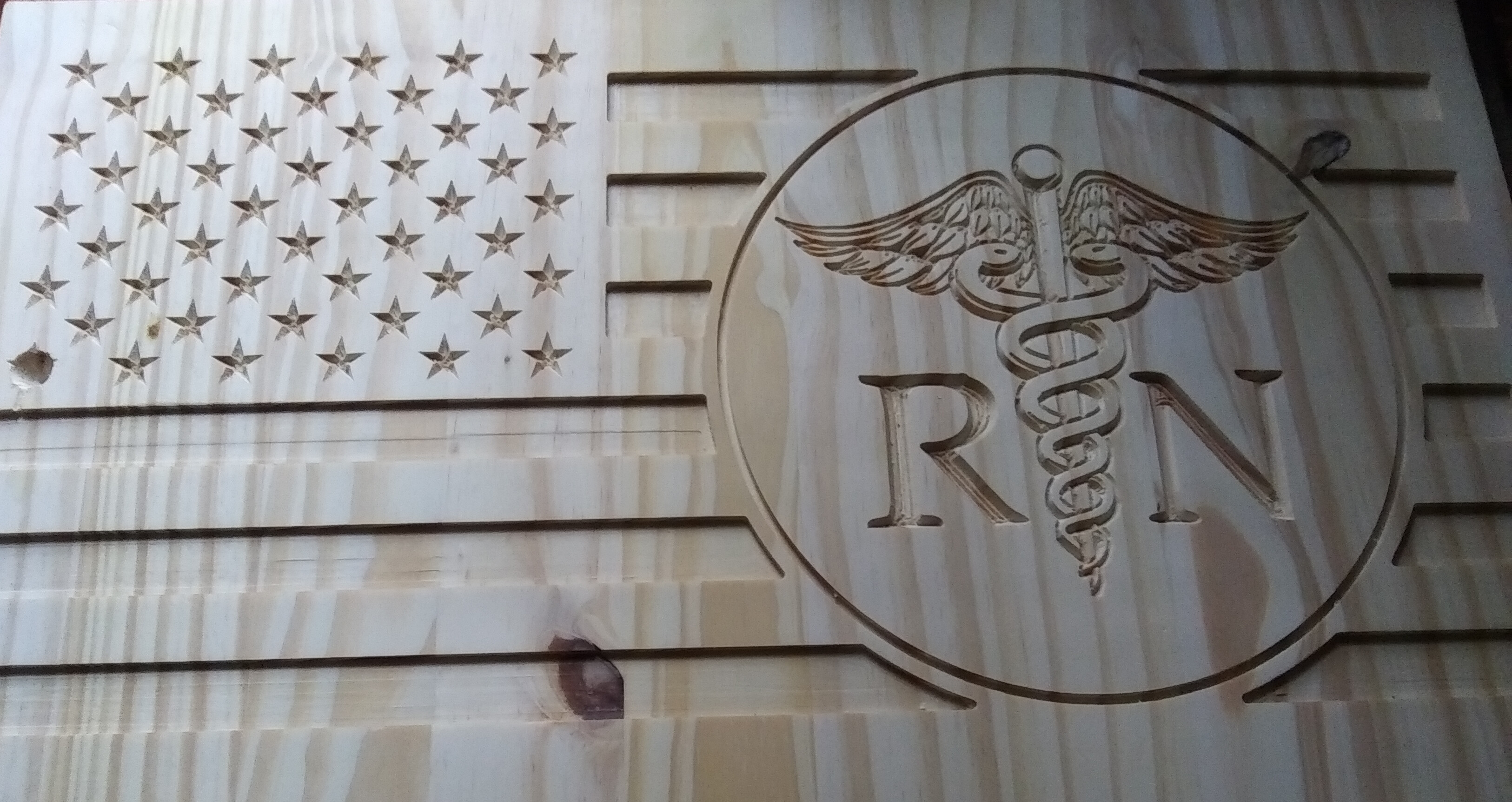
This is the first thing I have put together and carved out. Not much thought went into it other than trying not to break anything. I wanted to do something that used multiple bits, tool paths, and…
I used:
60* 1/2in Vbit on the stars, the lettering, and the emblem. I think the feed was 40in/min plunge 15/min - stepover .06 - stepdown .1 - rpm 15000
1/8 flat endmill on the stripes (pocket) and the circle (profile) I think the feeds and setting were about the same. I’ll have to look at my laptop later to see.
After using the probe and hitting start, the router went straight to the first star (bottom left) and burrowed into the wood and spoil board. Don’t know what I did wrong there. Then I used some paper to reset zero at the bottom left corner and hit start again. This time it went to the same spot but was acting like it was carving the star. It went on to carve the rest just fine. Well, I say fine but I really don’t know what that Is yet. There was some light sanding along the edges of the cuts that needed to be done and the center of the stars looks messy.
I changed the bit and started the stripes. First I did a profile of the stripes with a 1/8. I was planning on clearing what was left with a 1/4 but I forgot and just did the whole thing with the 1/8.
Can anyone think of anything I should have done instead? Is there a better way to do the lettering where the tool marks from the point are not so pronounced? Maybe a smaller stepover…IDK…?
@Swinly It’s nice work, despite the glitch. I can’t help you with Carveco. Others here use it and can likely reply to your questions. In VCarve, stepover is not used for V bits as you are not using them to clear out pockets or do 3D carving, where stepover determines how clean things are. The depth of the carve is determined by the distance between the lines that you are carving between. That is if you are using a vcarve toolpath. You can use a v bit and a profile toolpath, in which case, you set the max depth and the number of passes to get there. I suspect it’s a bit different process in Carveco, judging from previous threads.
I can tell you that I have found that it frequently results in cleaner v bit carving by running the same toolpath a second time. Mark Lindsay, on his Youtube channel put me onto this and I find it does work.
@gwilki
When I setup the toolpaths I did it in sections to simulate a larger project with many different paths. During a pretend bit change I forgot to load a new toolpath and ran the same circle profile cut a second time. It didn’t register with me until you mentioned it but it did make difference.
Well I flipped it over, stained, and went at it again for a bit this evening. Lesson for the day is to make sure that the clamps I do use are actually tightened down. Shortly after I hit start the board spun free.
Ahh yes, the Joys of CNC…wait until you hit a metal screw or clamp, or break a bit (especially that slightly expensive 1/32 bit to do a specific job), or forget to put the magnet on your collet when using the probe - talk about scaring the crap out of you…now where is that stop button…Carve looks fantastic, by the way.
Nice work! It is better to try something rather than watching others do it and never gaining the confidence to try. In the end, all of your learning will come from doing. What you get told will help of course, but it does not substitute for hands on experience.
The positional issue when you start has a couple of culprits. The obvious one is when you create the model in Carveco maker, you should specify the origin (0x, 0y start point) on the first screen where you input the size and the resolution of your workpiece. It is the small XYZ symbol in green, which you move to any corner or the centre of your model.
The issue you describe is probably more likely to be found in the toolpath arrangement. Carveco maker will generate the tool change code for you on certain conditions. Each tool must have a different number in the tool library. It is very easy to select the finishing tool first because it is the first option you select in the toolpath dialogue box. The roughing toolpath is selected next.
After Carveco calculates the toolpaths (say… one roughing and one finishing toolpath) when the save toolpath dialogue box appears, you have an option to save the toolpaths separately (left hand box if memory serves) or together (righthand box) and the file name if saved together is what creates the G code for the correct tool change. Ensure the save dialogue box displays the correct post processor for your machine. You must choose the correct one for inches or millimetres.
You could screen shot the toolpaths. One of the things that Carveco maker does real well is to simulate what you will get. If you do not change your settings, the simulation will probably have displayed the lines at the base of the letters. Not so much tool marks, more a case of specifying a stepover which V bits do not require. The step down is more important and to some extent a V bit decides on the depth it will cut because it is the space between the two outside edges of the letter that determine the depth of cut.
One method of V bit depth control in Carveco is to check the limit the depth box and specify the depth you want the cutter to stop at. Also cut on the centre line which you may need to add to the letters. For large letters it maybe easier to rough the centre out flay and then chamfer the edges. You may have inadvertently added a vector as well. It can happen when converting bitmaps to vectors.
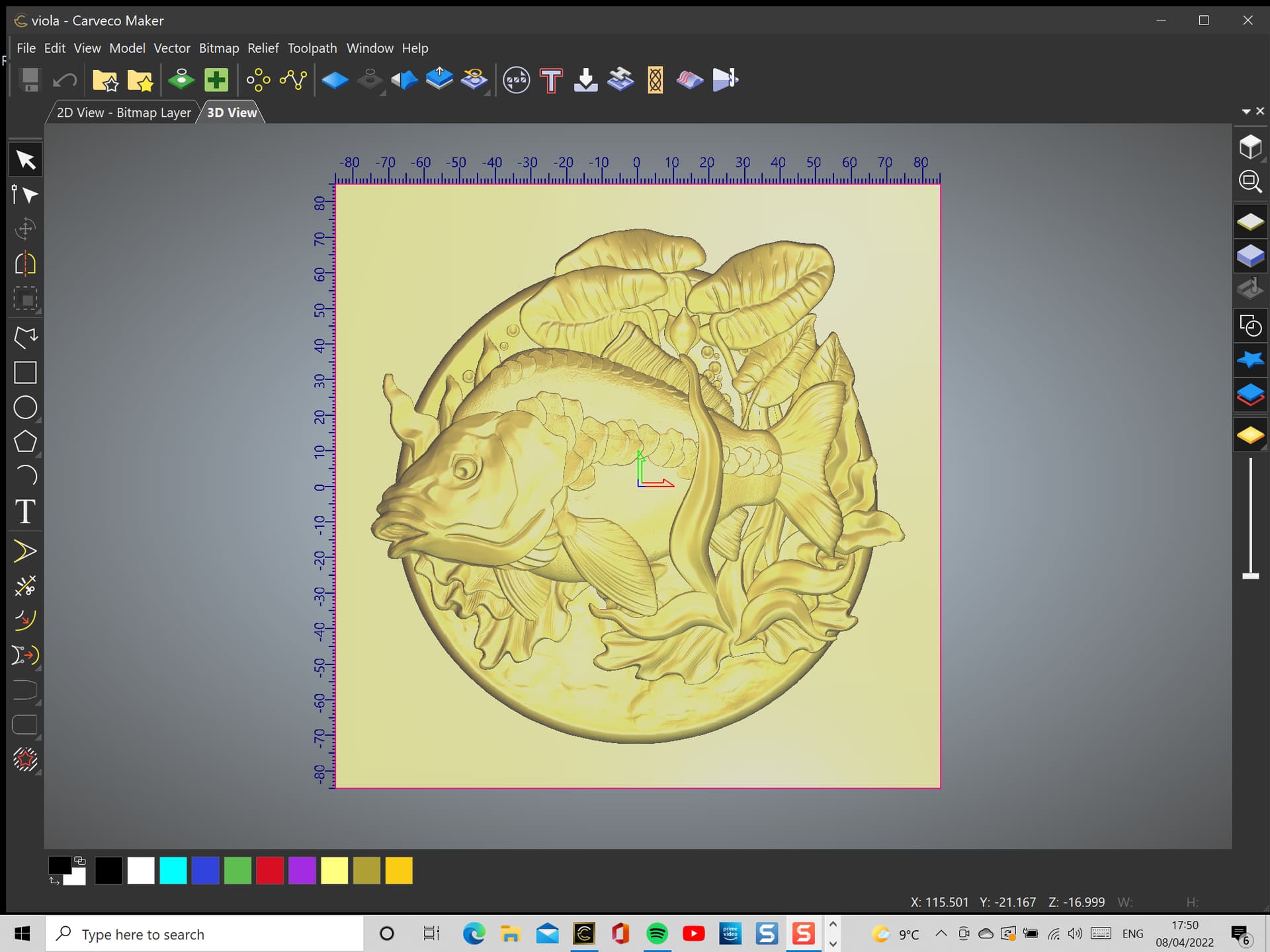
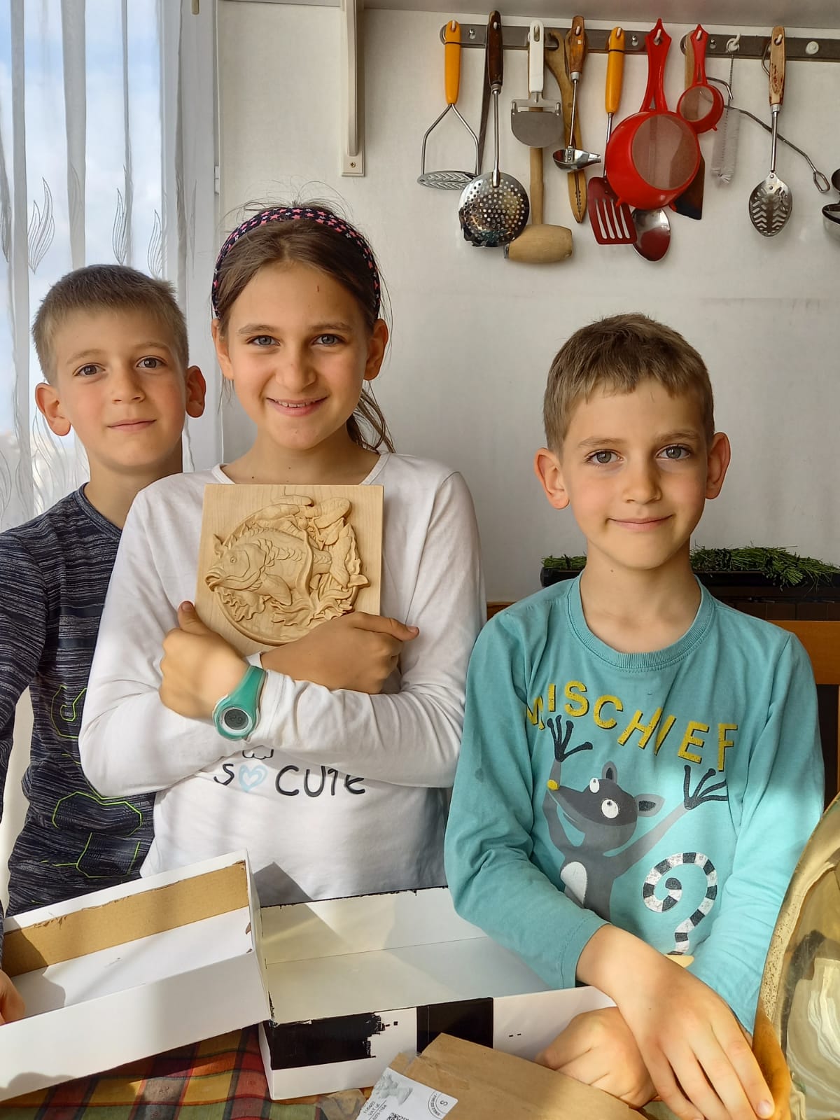
This may give you some ideas. As an illustration of the accuracy of carveco’s simulation. I have added a couple of images. This was a 3D piece cut in American Maple and finished by sanding to a grit of 3000 and then applying a creme of walnut oil and beeswax. It was for a young child and I did not want the finish to be toxic. The image gives an idea of how closely the workpiece followed the Carveco simulation.
Thank you for the nice comment. Sanding was not too difficult. Because I had a tramming issue, I had a couple of light (but noticeable) machining marks to remove from the flat, square background. I also had miscalculated the roughing phase and left some additional material (peaks between the 1/4" roughing troughs… which reflected the manner in which the roughing pass was done) on the circular dish outside. These would have been eliminated with an offset roughing pass rather than the raster pass used in this example.
The finishing toolpath was a spiral in a box pattern. It is a really useful toolpath machining strategy offered in Carveco Maker. It does not leave noticeable furrows in the workpiece and where a good finish and very fine detail is desired, I have come to really like this machining pattern. There is a plain spiral toolpath strategy as well but my work-holding solution uses modular vices and I have no wish to machine the vices.
The sanding was a very small amount of hand sanding of the detail of the square background and the edge of the frame containing the artwork. A fter using a fine, soft brass wire brush, to remove any wood chips still adhering to the fine details, I used normal silicone carbide abrasive paper from around 180 up to 3000 grit. The sanding required about 15 minutes. The piece was for a young child so I protected the wood with a creme of walnut oil and beeswax. It is used for food chopping boards and it darkens the wood by the tiniest of amounts but the finish feels good and the wood smells nice.
Here is a short clip of the process used to machine. (8:49)