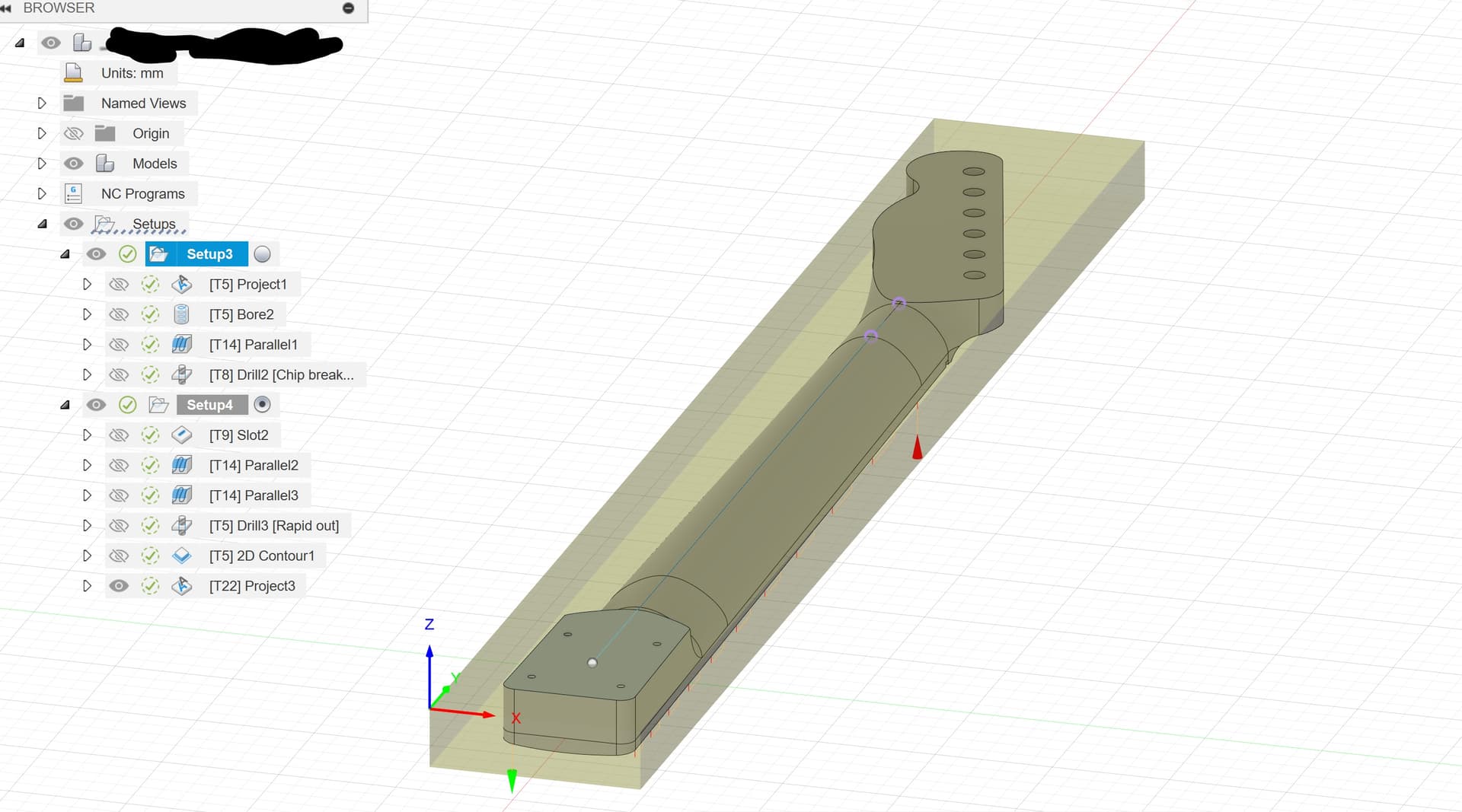
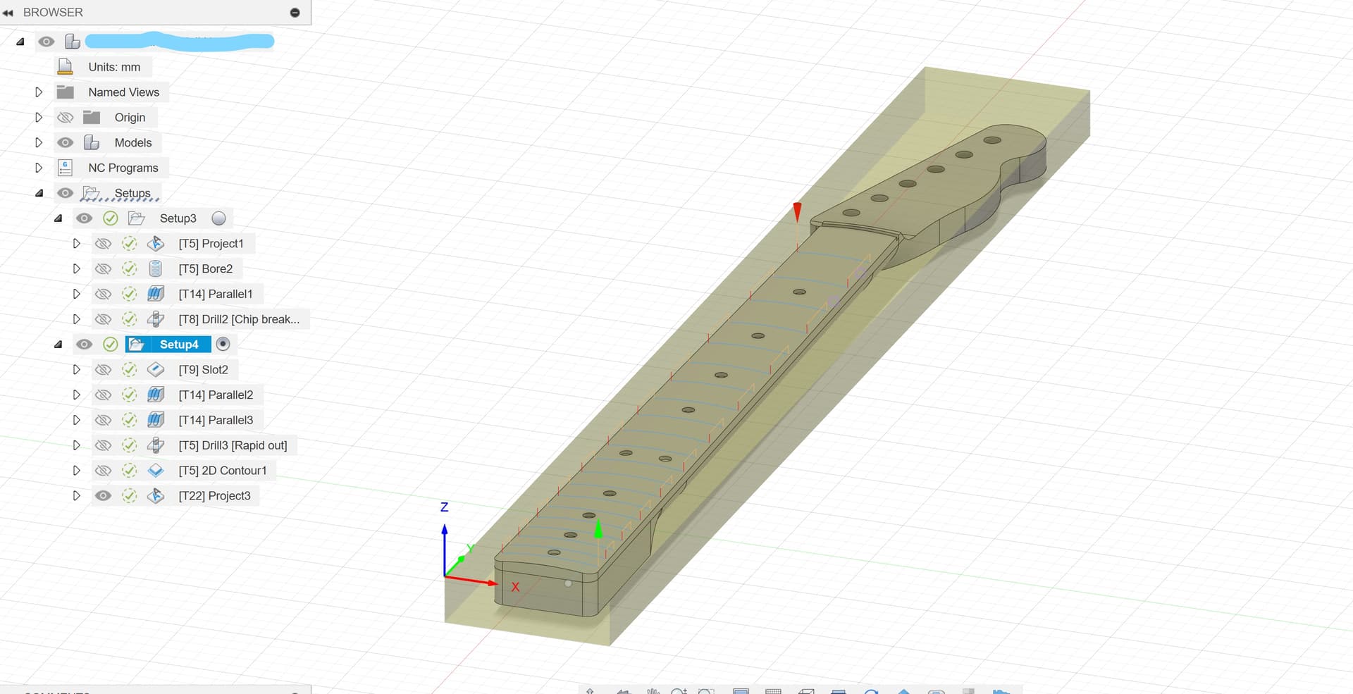
I am attempting to carve the front and back of a guitar neck using Fusion 360 and gsender.
The stock dimension is set to 25.490x710mm. I created a stock model with those dimensions and milled it out of a larger piece. Verified dimensions to be accurate with calipers.
For alignment, I use a large flat metal square taped to the spoil board with the long edge aligned with a t-track slot milled with the machine along the Y-axis.
First I use double-sided tape to align the stock with the inside corner of the square. Then I run through those cuts for Setup 1. For Setup 2, I flip the stock along the long edge and repeat.
I make sure to rezero the machine for every new tool (autozero touch plate). I also cycle power to the machine for every new file loaded because I have found that the machine sometimes plunges upon starting the job for no discernible reason. Ruined many pieces, so now I basically disconnect and cycle power and rezero for every new job and I don’t have that problem anymore.
I have done this process 4 separate times and only one has come out decent. The other times have resulted in the top carve offset to the right. It doesn’t seem to be a consistent right offset, but rather a skew to the right as the model moves in the positive Y direction. I am pretty certain this is not a CAD or CAM problem because it is not consistently skewed between different attempts. I suppose I can’t verify which setup is becoming skewed, but its easily identified by comparing the back carve to the final cutout performed a part of the front carve.
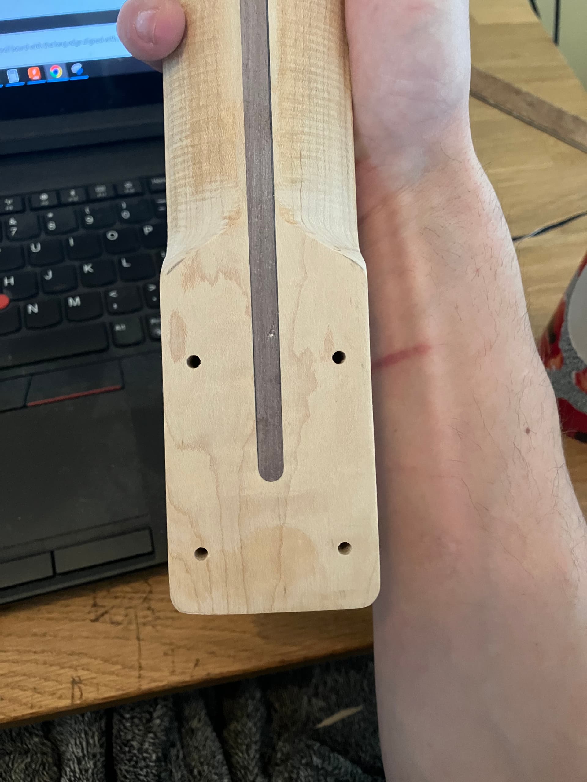
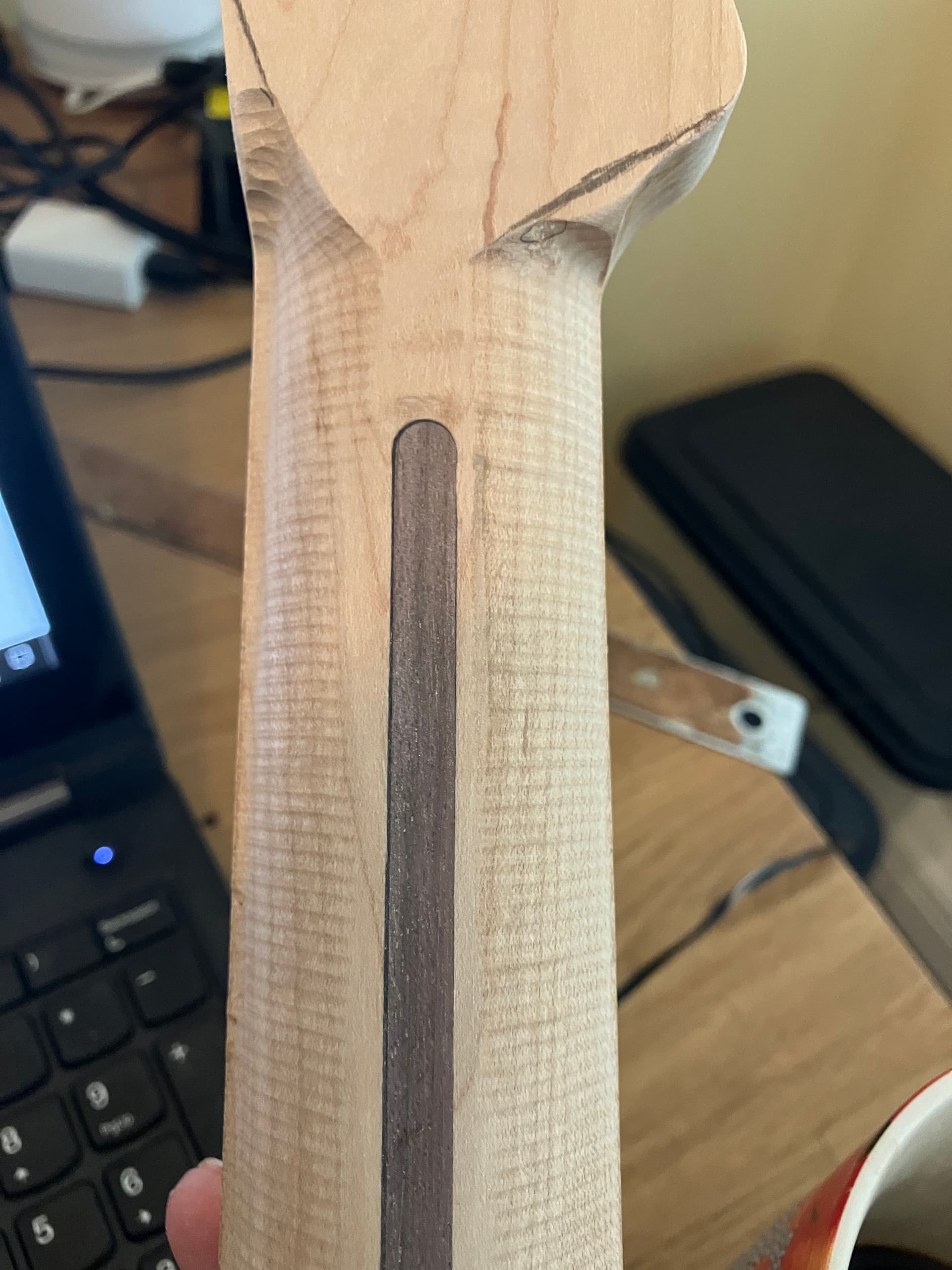
Below is the best example thus far. The first image shows the screw hole which are honestly perfect when compared to the cutout. The second image shows the top portion where the the back neck carve is not symmetrical because of the final cutout.
Very frustrating because have frankly wasted a lot of good maple on this thus far.
Any suggestions?
Your problem is fixturing; not software. When you have a double-sided project it is critical to have them aligned to the design when flipped.
The way you align them is with dowels in the spoilboard that are cut from the design.
There are many YouTube videos about ways to do this.
In my probably limited understanding, I am accomplishing a very accurate indexing with my method. The square is utilized to align the square edges of the stock. It is only the last cutout that separates the final piece from the stock.
So, this may be a problem. My gsender was Version 1.2.2. I have since downloaded 1.4.3. Perhaps that will help?
Now Gsender Ver. 1.4.3. doesnt run jobs. error 33
Setup 1 had a WCS Offset of G54
Setup 2 was set to 0.
Could that cause this problem.
I have no idea what WCS offset means.
WCS = Work Coordinate System
G54 is one of 6 or 7 “offsets” or areas within the controller that can be used. Generally known in gSender as “P1” (on screen.) This is generally where your machine starts after reset. It is quite easy to change to other WCS areas. I do this where I have different fixtures set out on my table for recurring projects.
I don’t know what you are referring to: “Setup 1” or “Setup 2”.
Sorry. Setup 1 and 2 are just the front and back of my project.
Where exactly are you seeing the misalignment? It’s hard to see in your pictures.
That won’t exactly align the two sides in all cases. Do research. Don’t rely on intuition. 
Use dowels and dowel holes to index the two sides. Use at least 2, but 3 (asymmetrical) eliminates possible flip problems.
Okay, I will do more digging. Thank you.
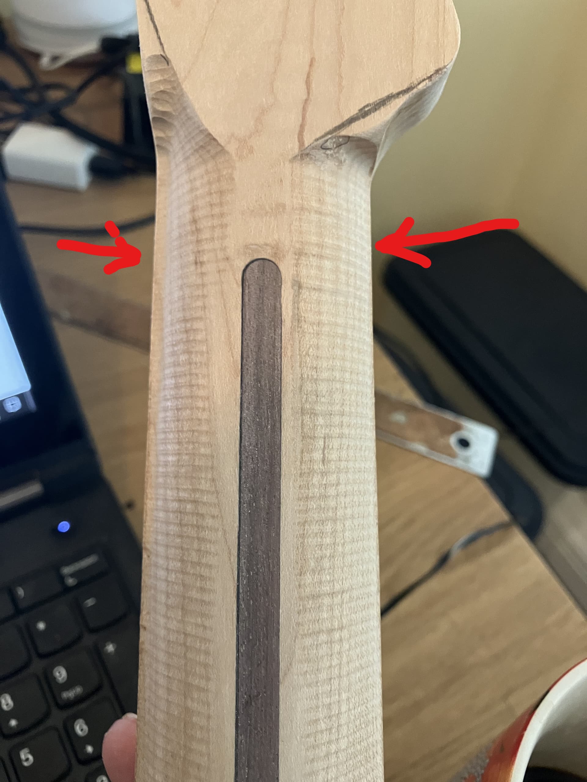
If you look at this picture.
The rounded carve on the back is skewed slightly to the right. You can see the end of the1/4 radius tool path mark on the left side but not the right.
I actually burned the worse examples already, but I wish I hadn’t because they showed the issue much more explicitly.
I really think my indexing method is fine. I can’t really comprehend how the dowel method would change anything. The square is referenced to the x-travel, and the stock is referenced to the square.
So now I think there is mechanical slippage somewhere or the older version of Gsender (1.2.2) was giving issues, because it gave a me a lot of other problems.
Do you think slowing down the feed rate will help keep position?
Do you think it is stupid to rezero X and Y after every tool path? Is that introducing errors? Obviously tool changes require z to be zeroed. I don’t trust the machine to find the original zero because I have seen it fail to do so before.
I see now, thanks.
There’s are two things I would look at first that would cause that issue.
One, your stock needs to be exactly the defined size and EXACTLY square doing it this way. The dowel pin method eliminates the need for that requirement as @CrookedWoodTex suggested. The other possible issue is the motion of the machine not being entirely square to your square. Every time you power off the machine and power back on, the steppers can jump throwing it out of square. Can you test by jogging along your indexing square with a sharp vbit to see if it’s still square to machine travel?
This is very possible as well. But you said the alignment is off on an angle, right?
My machine is square to within 1 mm.
Does your reply mean that you did what Neil asked and found it to be “within 1mm?”
1 Like
One thing that’s essential for two-sided projcets is to have your machine set up as close to perfect as you possibly can. By that I mean that the X and Y positions need to be bang on. gSender has a feature that allows you to calibrate your machine within “an inch of its life”. Once you’ve done so, then also ensure that the square you’re using for reference is very well bedded. I wouldn’t rely on tape to do so; clamp it down.
The other suggestions you’re received regarding zeroing your machine after each tool path has run, is correct. DON’T DO IT. If you’re having repeat problems with the Z axis diving down at the start, then get that resolved, as there’s obviously some problem there.
Let us know how things work out, okay?
Marty from Kingston, ON, Canada
1 Like
sorry for off topic but,
that is a lot, to where i cringe at my 0.01 mm out of square
Sorry, I mean that the X-Y squaring function in Gsender says my machine is pretty, but the left or right rail could be moved by about .074mm to make it perfect. I feel like that is small enough to be measurement error on my part.
The other suggestions you’re received regarding zeroing your machine after each tool path has run, is correct. DON’T DO IT.
So I can just zero the Z-axis when I change tool then?
If you’re having repeat problems with the Z axis diving down at the start, then get that resolved, as there’s obviously some problem there.
That problem has been resolved after updating to the most recent Gsender version.