I’m thinking it must be possible, so has anyone here done it or can point me in the right direction to learn how?
Hi @MikeH I’m assuming you made a typo and mean dome - sounds like an amazing idea, but I will start by saying I haven’t even done inlays yet, let alone on a curved surface.
This sounds like a really interesting challenge - from what I have seen in inlay tutorials, there are a few keys to getting a tight fit that mainly involve careful use of the angles and depths of the mating parts to get a good glue fit and “perfect” inlay look.
What type of thing are you looking to do? The radius / curvature of the dome you are working with will affect the draft angle (the way the cut and the inlay meet) - so it could be anything from not-so-hard to quite difficult to get it all set up. Also, once it’s glued up, you would then have to carve away all the structure of the inlay material, since you can’t use a bandsaw to get rid of it.
If I’m misinterpreting your question, let me know - and if I’m not, maybe we can work together to figure out some fun ideas for how to do this.
elbarsal, you are right, I meant dome. I fixed it.
What I am thinking, and what I have been playing around with ( early stages of a layout) is an oval cribbage board with the middle being an oval dome lid that would cover a pocket cut out for cards and pegs.
I want to inlay my grandsons name on the lid.
I think in theory if you took the exact same dome and inverted the curve, make it concave with the inlay cut on it, it should fit together, unless I’m missing something. As far as cleaning it up after it’s been glued up I can take most of it off with my bandsaw then go back to the original convex pattern and re-run the tool path and run a very clean last path.
As I was thinking about this and I started to wonder about cutting raised letters on a concave surface. I think because the router is fixed in the vertical the angle of the cut would be different in the concave vs the convex so I don’t think it would work. Maybe if the male part, the inlay part were also cut on a convex dome they could be cut into individual letters and used that way. Might be a pain but if a guy could do it it would be pretty cool.
I could see it working if the curvature is big enough - and I think to nail it, it would require Fusion 360 to be able to use some advanced modeling.
Here’s what I would envision:
- Model the dome surface
- Project the text onto the dome surface (haven’t done this yet, I think it’s possible but might be tricky)
- Extrude the text into the dome surface, with a taper angle equal to the bit you intend to use to cut the lettering
- Create the inlay stock block
- Use the convex dome you have just modeled to “cut” the inlay stock, leaving the concave negative of the dome and lettering
At this point, you would have two pieces to cut - the dome, and its negative.
- Cut the dome in 2 passes - 3D adaptive clearing, then radial
- Engrave the letters
Cutting the negative gets a bit fiddly:
- Cut a concavity at the outer height of the letters
- Clear between the letters (3D adaptive clearing + some finishing pass?)
- Chamfer all the letters with the same engraving bit from cutting the lettering into the dome.
I can see how this could work, with some fiddling of parameters and values to get best fit between the inlay and the dome - but it would be quite a project. Once the pieces were glued up, you could then repeat the process of cutting the dome (adaptive clearing + radial) to remove the waste inlay material. A key variable is the curvature you are attempting - as you said, the fact that the router is vertical adds some limitations here - but you do have me very curious.
Can you estimate the maximum curvature you would be looking at? I could envision 1 inch of curve over 12 inches of run being doable, maybe even 2 inches over 12 (or any fraction / multiple) depending on the thickness of the material and the angles of the carving bits used. I’m going to have to take a closer look and see if Fusion can do all the things needed - this does sound intriguing.
It would be cool if it could be done. I am using a 60 degree dome in Vectric, I don’t have any 3D modeling software. I have been wanting to play around with epoxy inlays also, I might do that instead. I think for now the inlay on a dome is above my pay grade. but it will be rolling around in my head. ![]()
1 Like
@MikeH What’s the diameter of the dome?
Thanks @MikeH , now it is rolling around in a lot of heads… ![]() not above your pay grade, just have to figure out the software. Those folks at Vectric have been doing wood cnc stuff way longer than any auto anything and it is 3D software or I wouldn’t use it.
not above your pay grade, just have to figure out the software. Those folks at Vectric have been doing wood cnc stuff way longer than any auto anything and it is 3D software or I wouldn’t use it.
web search for vectric dome inlay
It might be faster to do the inlay first and then cut the dome. Deep inlay with a sharp taper bit, scale the inlay to the expected final size. Or just don’t do the male plug and fill the vcarve with epoxy and do the 3d rough and final cuts. Z axis is always vertical as mentioned so we have to compensate for that.
and good question @gwilki material thickness will factor in so angle of dome may have to be adjusted.
If you don’t post pictures of your results, it doesn’t count…
1 Like
I haven’t tried to mill this, but a little work on paper leads me to believe that this could be done as a v-carve inlay in Vectric as long as the lettering doesn’t go too far down the sides. The lower the angle on the V-bit, the farther you should be able to go down the sides.
The setup would be the same as a normal v-carve inlay just projected onto the surface of the dome. I would like to test this actually, to see if my paper drawing holds up, just need to find some thicker stock to try it with.
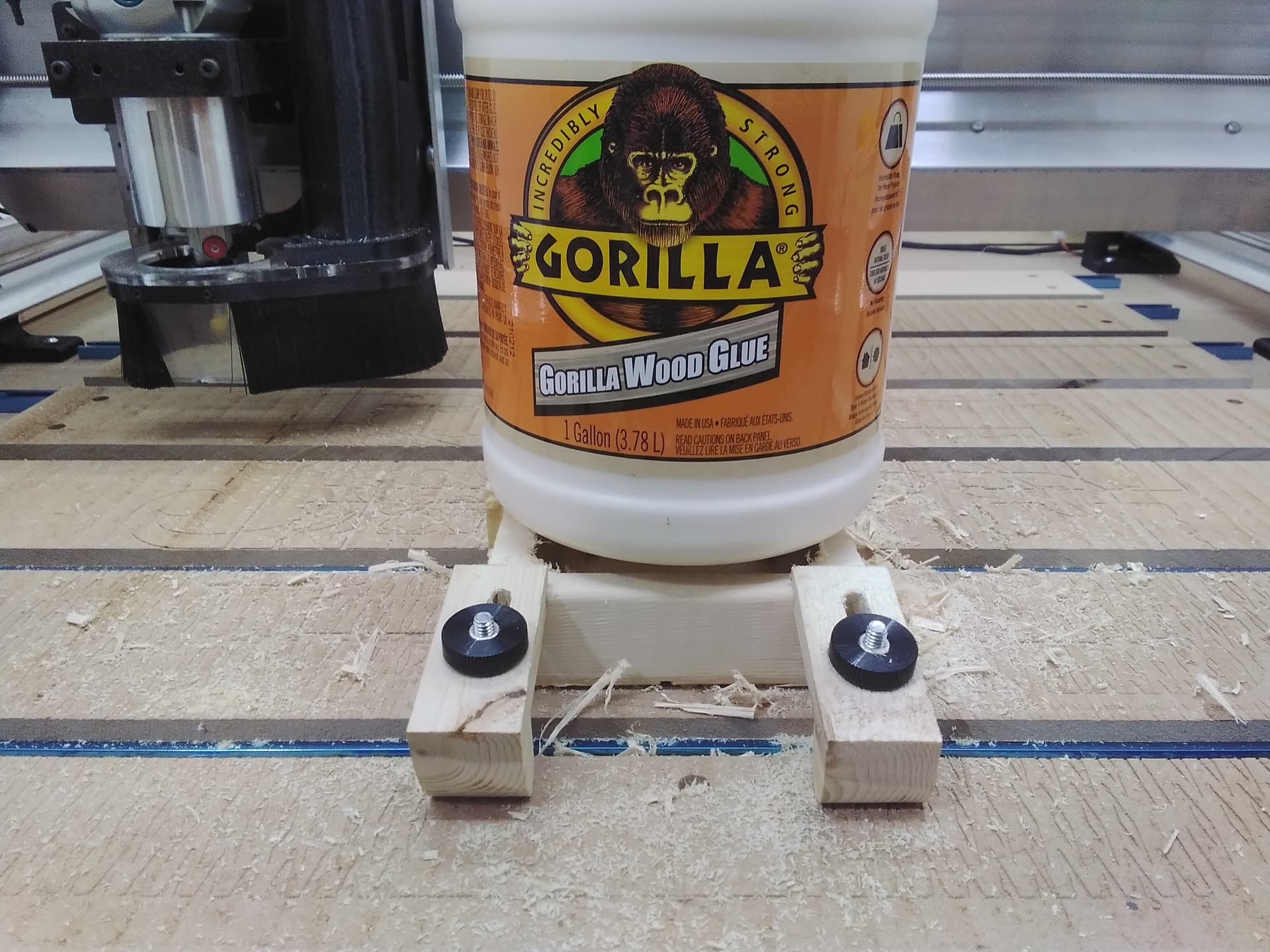
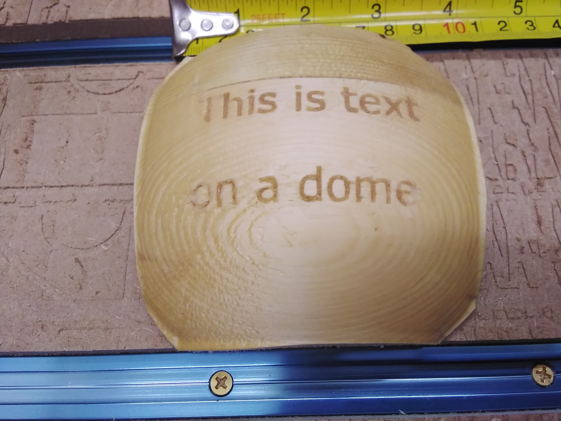
So first I start with only the finest of materials, MDF and 2"x4"s.
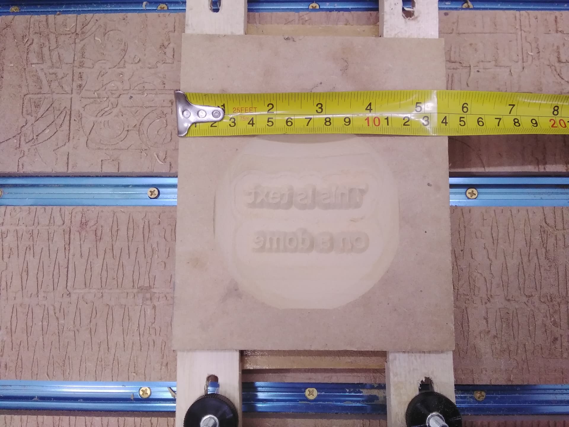
And then I glue them together…
And then I go crazy and don’t wait long enough for the glue to dry and or being to aggressive with the waste removal.
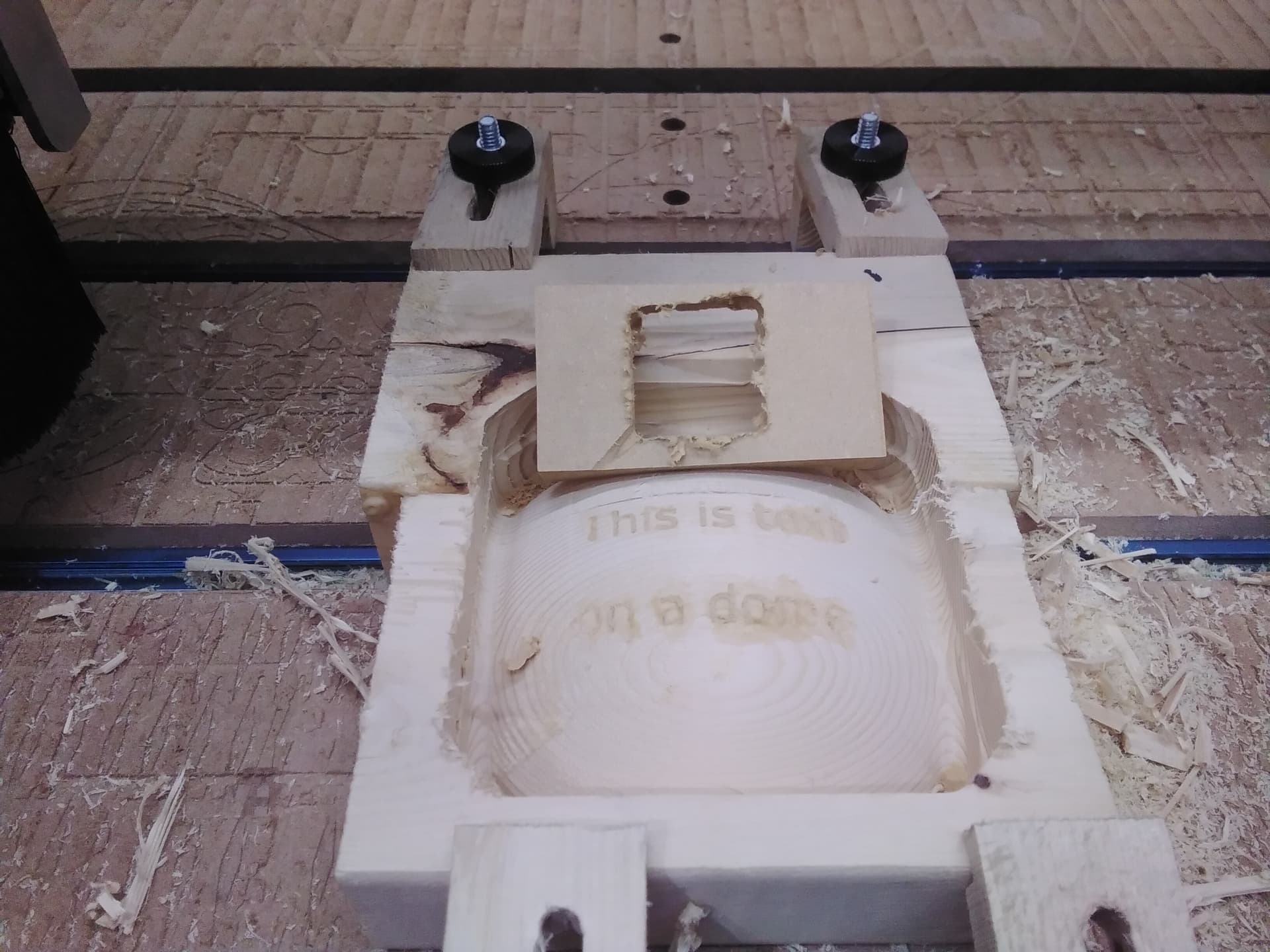
Despite the couple of letters that messed up when it ripped apart, I think it is enough to prove that it can be done.
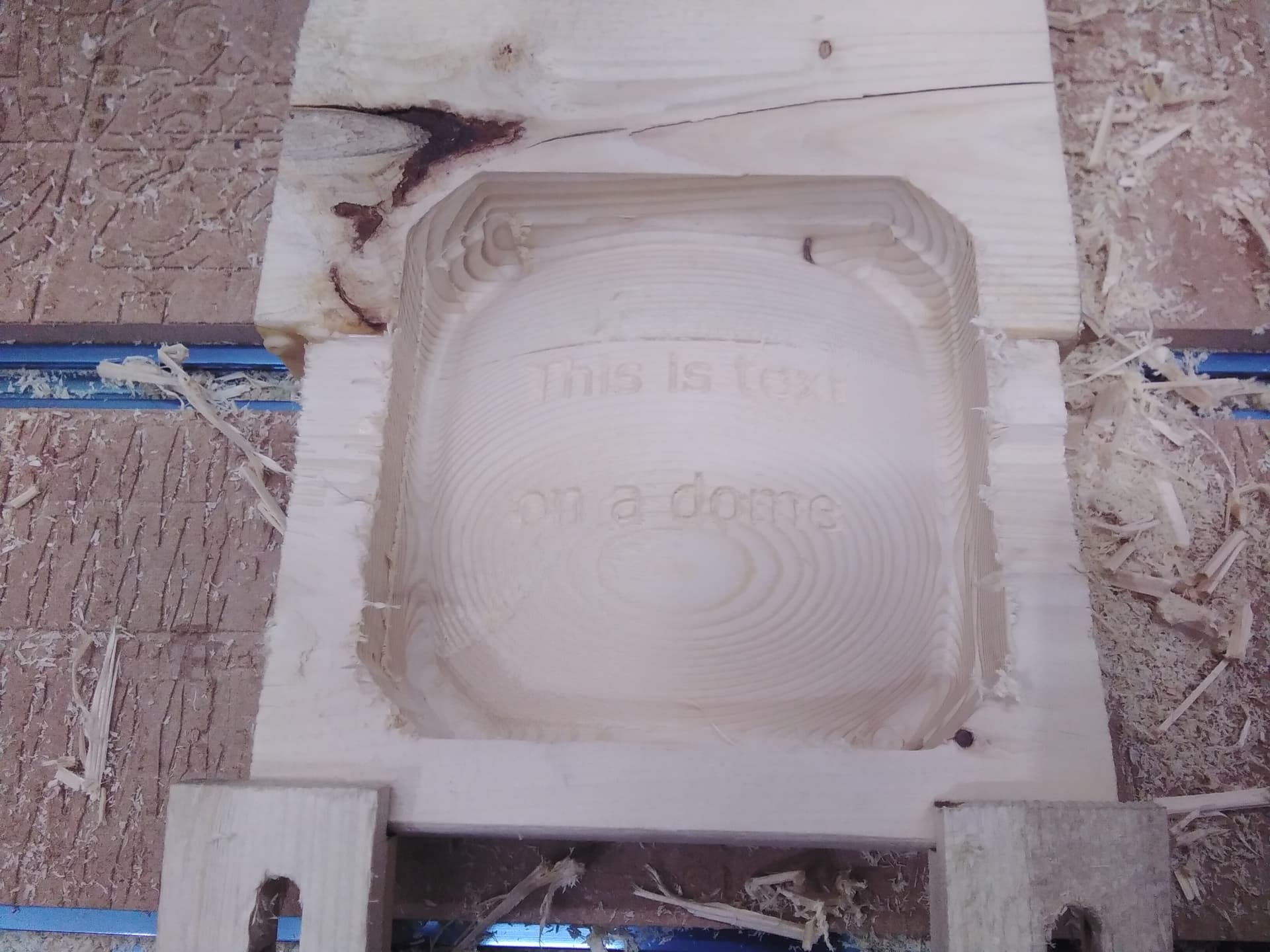
I started with these two models that I made in OpenSCAD.
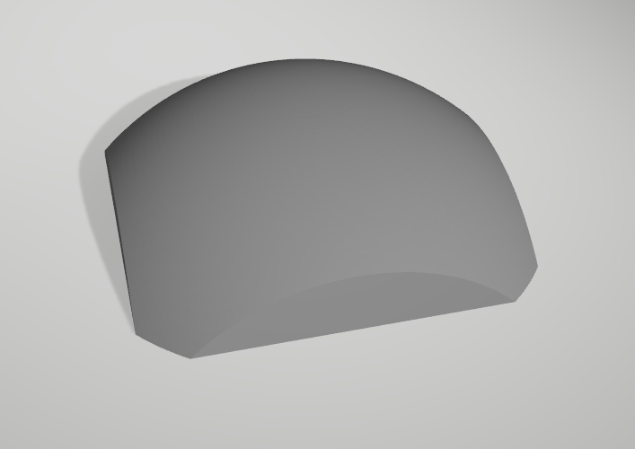
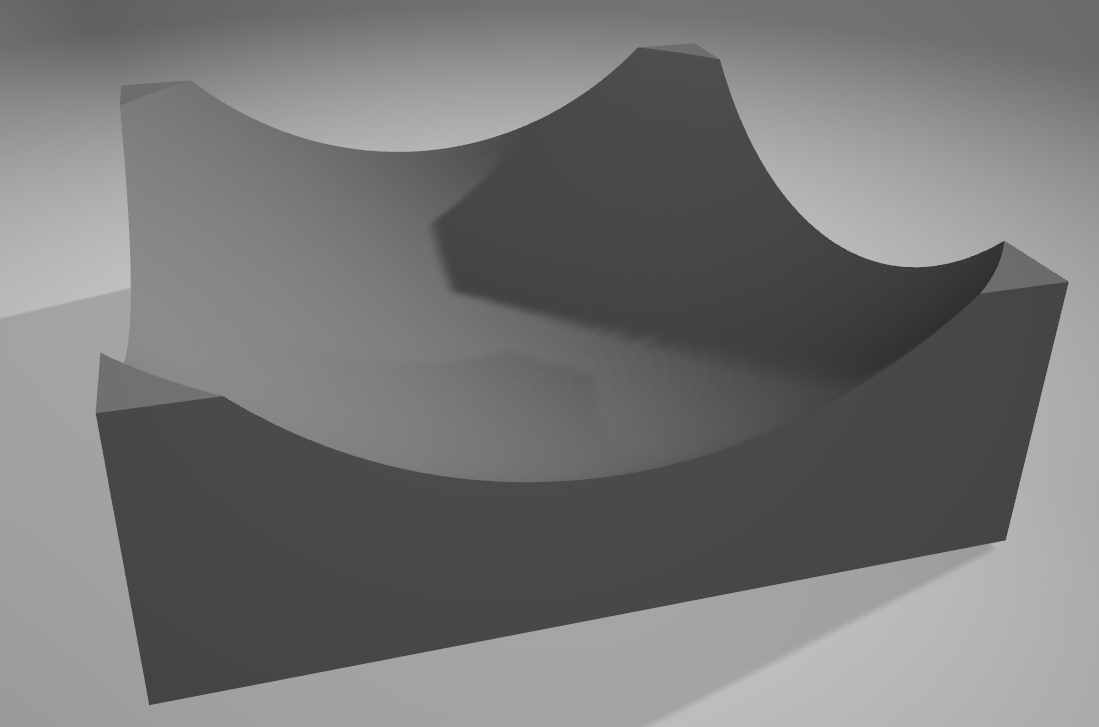
And then I used Vectric Desktop to do a regular v-carve inlay only projected onto the models.
For v-carve inlays I follow this guide.
VCarve_Inlay_Description_and_Procedure.pdf (1.1 MB)
I hope this helps to encourage you to keep going with your cribbage board idea because I can’t wait to see it!
Oh and this was done with 1/4" ball nose, 1/4" end mill for roughing and 60 degree v-bit. If I had to do it again I might try a 30 degree engraving bit for the v-carving because with text this small it wasn’t very deep. I imagine your project will have to bigger unless you have a very small deck of cards so a 60 degree might be fine on yours.
2 Likes
@_Michael that is a fantastic proof of concept - I haven’t used Vectric so I didn’t know it could v-carve on curved surfaces - looks like it does the trick nicely. Now I might have to see if it can be done in Fusion (which seems to be the hard way when it comes to v-carving, but it’s a powerful package nonetheless).
@elbarsal There isn’t much that can’t be done with Fusion. I’ve used it for 3d modelling, but never took the time to figure out the tool path part of the process in Fusion.
Thanks for the encouragement and ideas. I did get motivated again the other day and ordered some 30 degree V bits. This dome is about 10 inches and I started thinking as Micheal did that if the v carve was not to deep this could work. When I get a chance I’m going to give it a try. Right now the garden and lawn are keeping me busy plus the floor of my shop has a bunch of oak and cherry lumber I’m planing for a friend. Busy time of year in Wisconsin.
I’ll let you know how it goes and please keep posting ideas and any progress you make with Fusion.
Michael, I started laying this out but I’m not sure how to lay out text on a concave surface. I looked for some youtube vids but didn’t really find anything. Can you point me in the right direction. I see you used SCAD program, not sure what that is, would it be required to do it or can it be all done in vcarve?
The dome could be made in any program that can make it. The project onto 3d model is located at the bottom of the toolpaths tab.

You can see the 3D model in the 2D view just place the text where it should be and that checkbox will do the magic.
I did project it on the dome with no problem but I’m not understanding projecting it on a concave surface. I am able to v carve them into the concave but not get them to stand proud. I would need to make them proud of the hollow. I would have the bigger carved area then I would need a pass to cut out the letters Using the same bit as the pocket. That’s where I am struggling.
You need to flip the text left to right so that it is backwards and to have a shape around the letters. With the shape around the letters it will v-carve between the letters and the outside vector. I used the modeling tool ‘Create vector boundary’ on the 3D model to get the outside vector.
Do I also invert the dome? so it is all a mirror image?
If you already have the dome as concave you should be all set.
Maybe it depends on if the dome is symmetrical. If it not symmetrical then you may need to flip it. Like if it was an egg with the pointier end on the right for convex then the pointier end would need to be on the left for the concave so when you turn it over it all lines up.
Hope this makes sense because I don’t generally think of eggs as pointy ![]()