Random CNC machine improvements

The CNC machine I had purchased about twenty months ago was unsatisfactory in several respects. I had not assembled it with due care and attention. The machine, the smallest sized Shapeoko SO3, required about 6 weeks to assemble the machine so that square meant square and smooth travel meant smooth travel. One of the things which had become clear to me during the first few months of ownership is that making a baseboard from MDF (the supplied one one was 18mm in depth) is possibly a poor policy but it obviously keeps the initial purchase costs down.

Using clamps from several different clamp systems, I found milling some jobs awkward. I thought I could cure this by applying M6 threaded inserts to an MDF baseboard to a depth of 10mm and placed from underneath the baseboard. This strategy sort of worked and I could secure workpieces to the baseboard relatively easily. I had not considered the repeated tightening and loosening activity and it was after about a month of use that I had noticed that some workpieces moved slightly when being milled, when clamped, using Carbide’s stainless steel clamps.

Using an MDF spoilboard helped me to position the workpieces accurately. I had discovered 3M painter’s tape and CA glue and that helped for some projects. What had become clear was that work-holding was an important link in the chain of accurate working. It should have been obvious but it takes a while to note all of the important skills required for accurate CNC working. I had intended to mill metal (brass and aluminium) and I could see that much better work holding was required. It also underlined the conclusion that the more rigid one could make the machine, the better the performance was likely to be.

I purchased and fitted an aluminium fixture tooling plate. It had 840 M6 holes evenly distributed and it was 12mm thick. I also ordered two pairs of modular vices from the same manufacturer (SMW) This was not a particularly cheap option (basic cost plus importation taxes and transportation fee) but it changed everything I do for the better. I would tell any user that making the machine rigid, through the use of a metal baseboard, is probably the number one modification before undertaking any other modification work. It makes a significant impact on work-holding, reproducibility and ease of use.

Aluminium baseboard and modular vices are all from Saunders Machine Works. These items can be found at the following link.

https://saundersmachineworks.com/products/carbide-3d-shapeoko-3-aluminum-fixture-tooling-plate

The other vital adjustment was to the poorly designed belt tensioning system. I realised that inaccurate tensioning of the belts combined with the problematic maintenance using a belt manufacturer’s application (Gates) that produced rather variable results… was unlikely to assist me in my search for accuracy.

There is a gentleman (@NeilFerreri) who had posted a belt tensioning device on Thingiverse.

This was a great idea and I was able to get the components 3D printed, by Liam Newcombe, from the Carbide forum. These belt tensioners required some surgery to the endplates of the extrusions but now they are fitted, they work well. It takes me around 20 seconds to tension a Gates GT2 belt to 135Hz, which equates to a musical note of C3. I use a very cheap frequency receiver that works by vibration. I had used a sound receiver but the ambient noise made this an unreliable device in this specific context.

Now that the belt tension and the machine rigidity are much improved, I can routinely mill metal (T6 6061) to a depth of 20mm. using 0 flute, DLC coated. The tolerance which I can obtain is routinely ±0.0254mm (±0.001) and I am happy with that result.

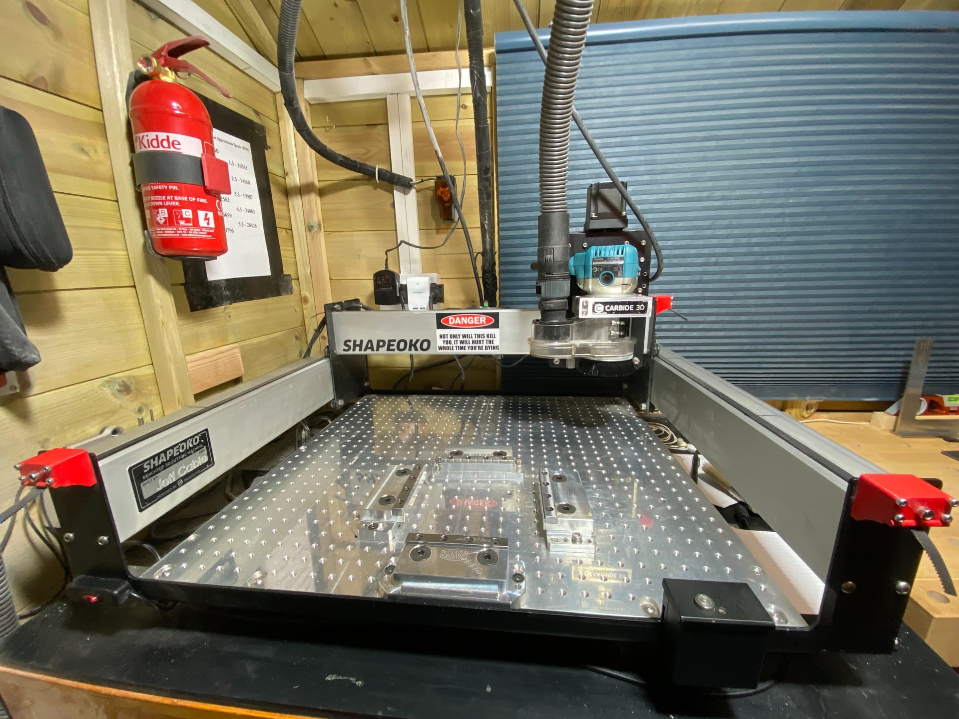
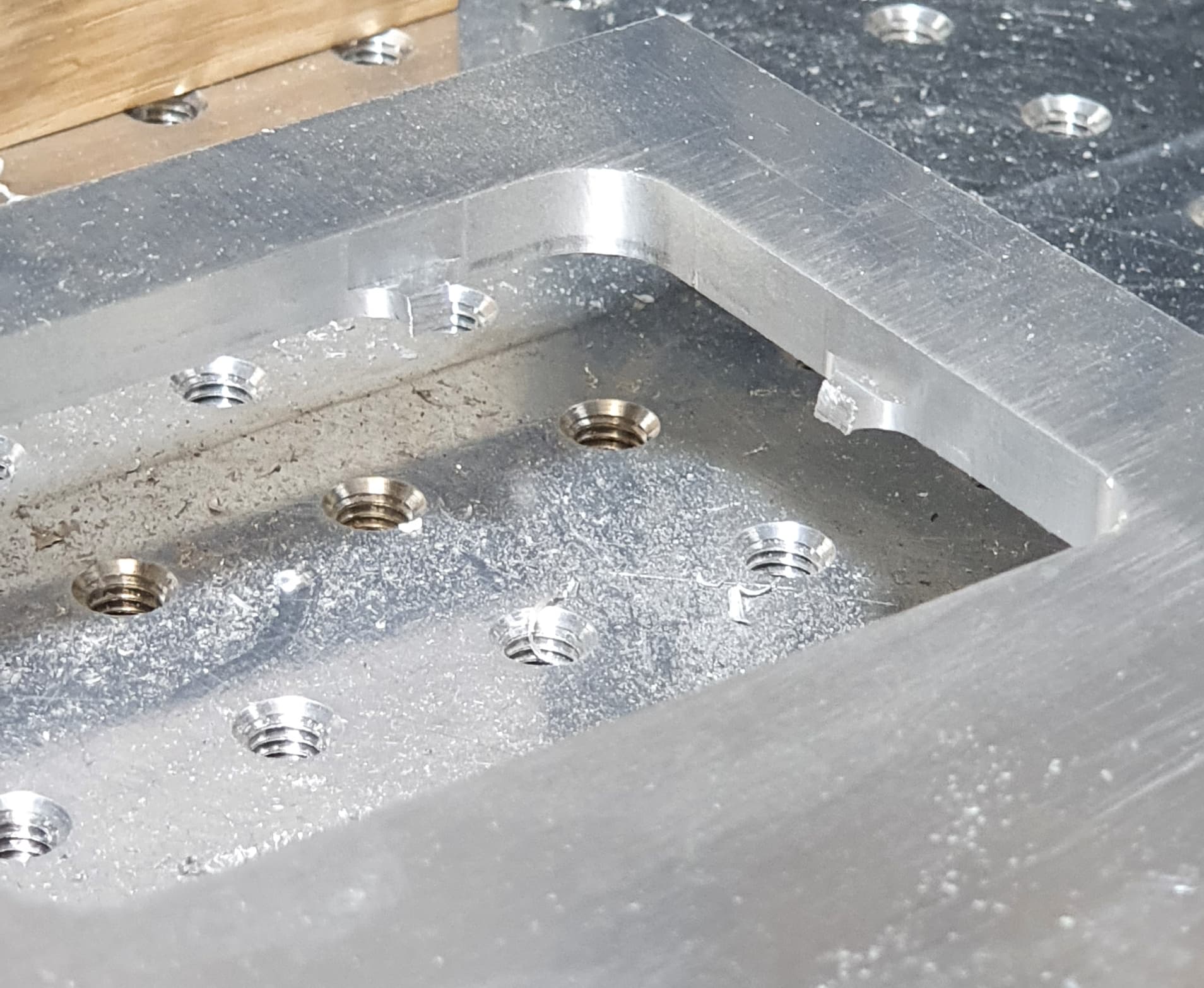
Images may help understanding… Here is an overview of the SMW fixture tooling plate in situ.

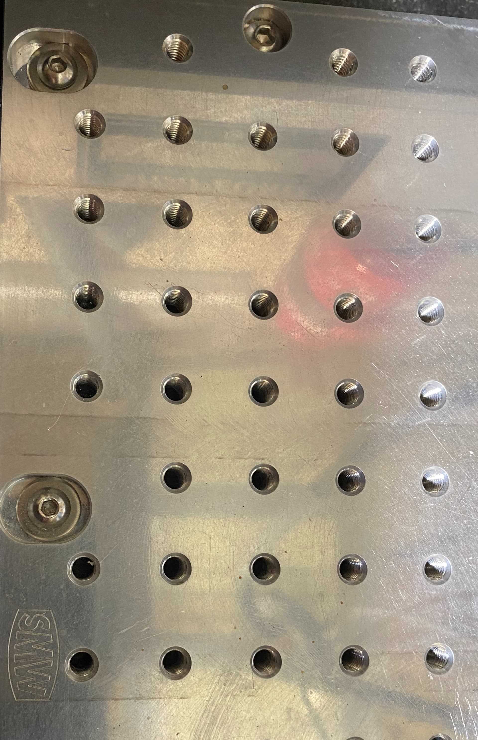
This image shows the machine tapped M6 holes.

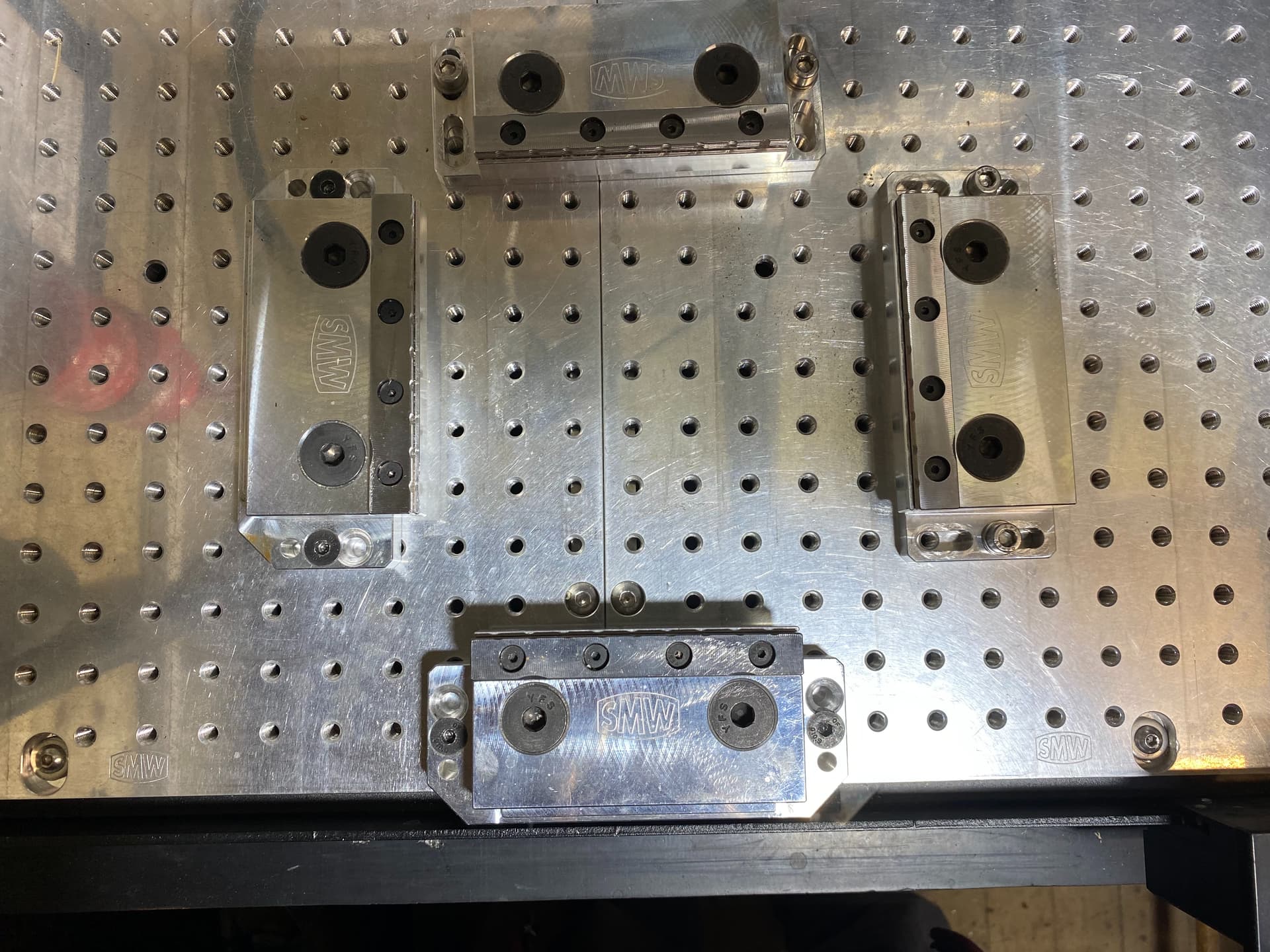
The modular vices can be set to any width and I frequently use them in this configuration.

This is a side view of the much improved belt tensioners. The belt is now parallel with the Y rail whereas previously, the end of the belt was twisted through 90 degrees and then doubled under itself. To say that they could take a long time to adjust accurately is an understatement.

Machining aluminium is no bother, if you use good quality endmill bits. I use a supplier in the UK who charges reasonable prices. DLC coated endmills with a single flute are supplied at £5.28 ($6.59). The 1/8" endmills are sharp and last for about 20 cuts. The feed and plunge rate should not be too aggressive.

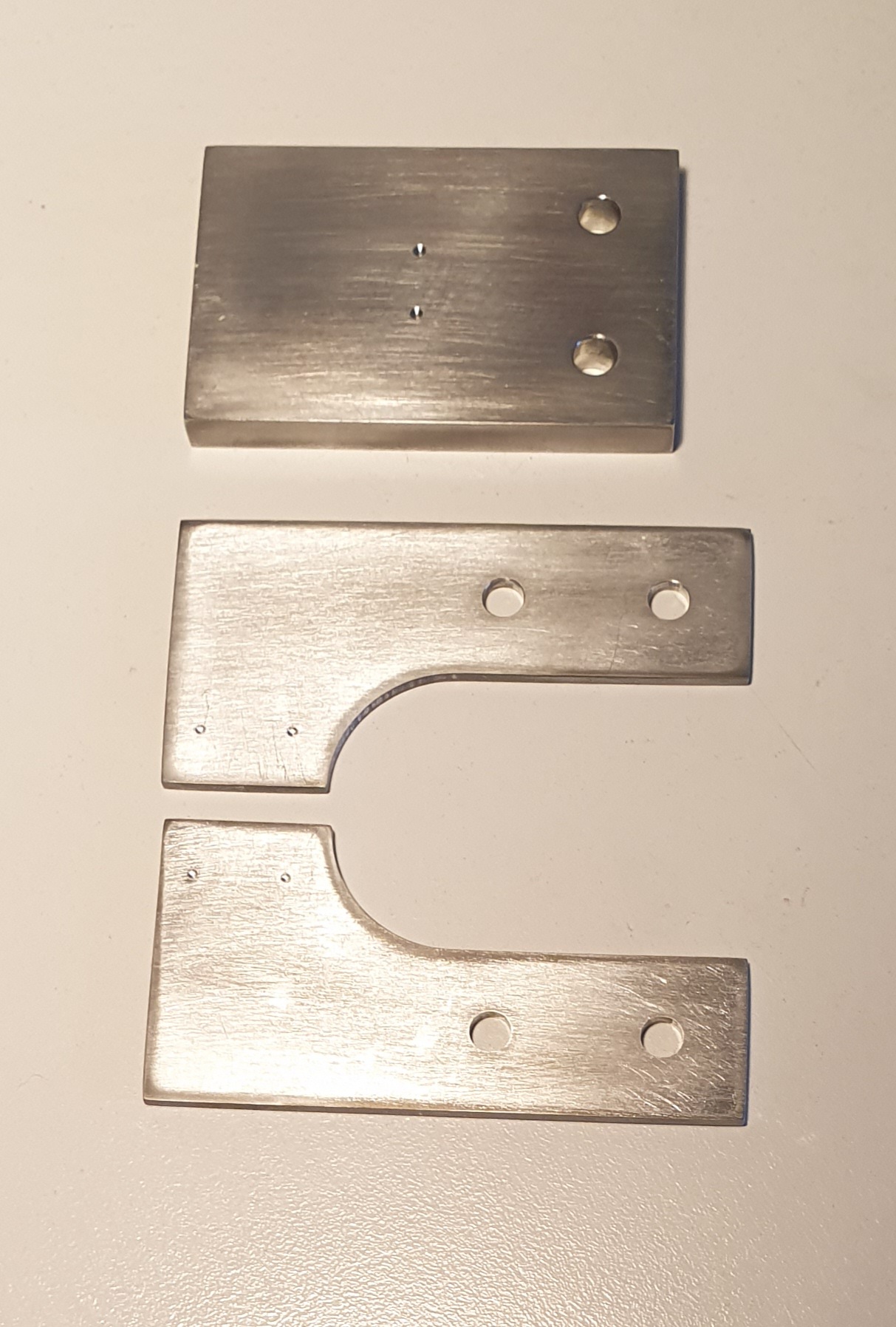
Recent aluminium projects: A new depth stop for a cheap pillar drill. Cut from 6mm x T6 6061 aluminium. This was my first aluminium project so it could be improved.

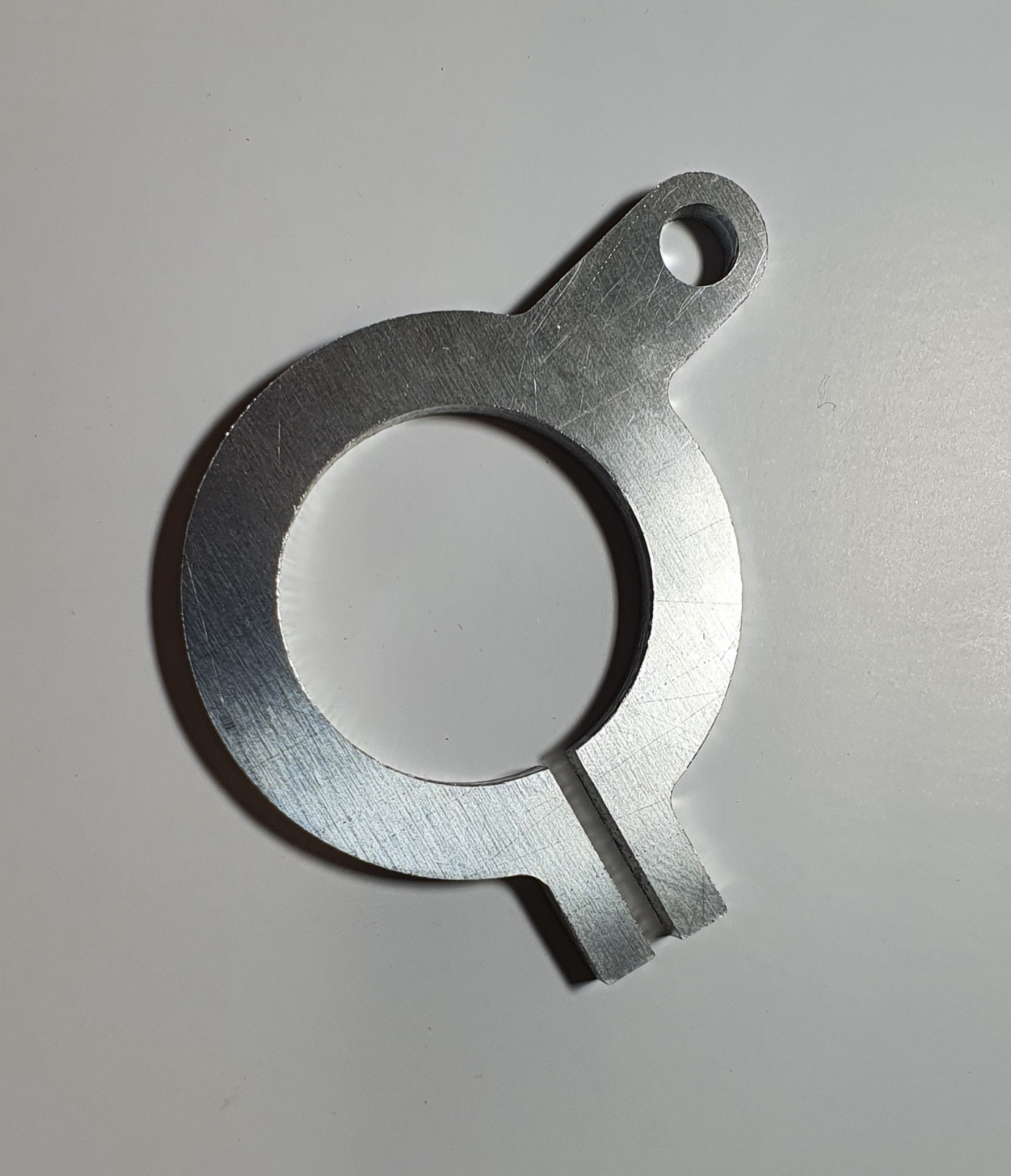
A recent project in 6mm and 2mm T6 6061 aluminium. The index holes are from a simple carbide drill for milling. They are .2mm in depth and will allow the user to drill holes to size to suit the job. The 5mm holes were not drilled. I like to use a helical milling technique for holes that must be accurate.

The hole remaining in the workpiece after cutting a 6mm rectangle. The cut edge is fairly flat with the expected lines at each edge of the tabs. These appear as the Z axis moves up to leave the tab. I was cutting using a .2mm stepdown and 10,000 RPM.

Two views of a DLC coated Rennie 1/4" single flute cutter. This cutter appears to be uncoated but I have used one for about 40 jobs.

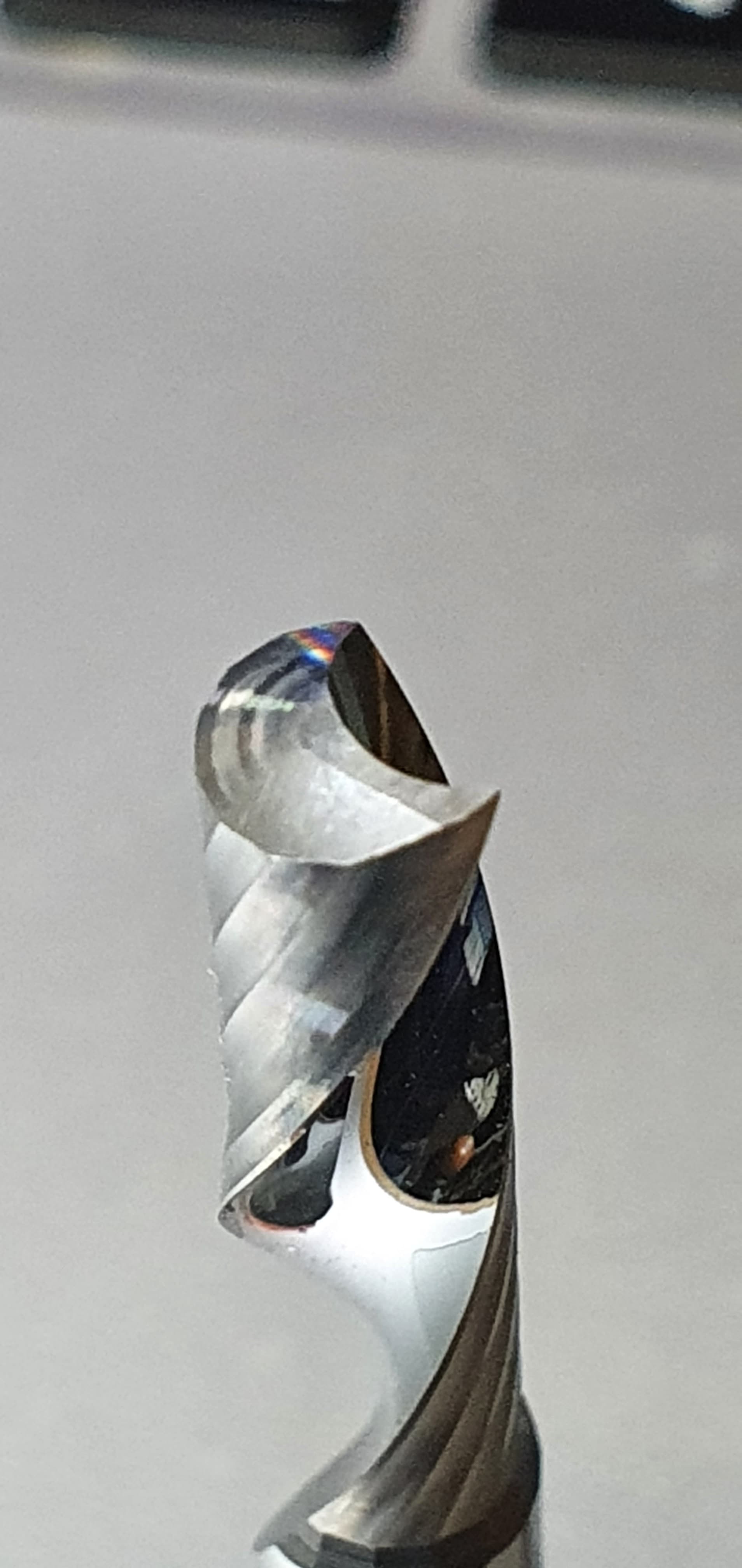
Agood view of the single flute architecture.

The final image is a small MP4 clip that shows the milling of the pillar drill depth stop.

In summary: If you want to modify your machine, the biggest gain will come from increasing its rigidity. That is for milling and work holding. Uneven tension of belts (or lead screws) will affect the final dimensions of a metal workpiece. Only use good quality cutting bits.

I know it can seem to be attractive to buy 10 x single flute coated bits for milling aluminium for $10. The quality of the bit is reflected in that price. They will exhibit large runout and make a horrible noise while milling the work piece. The surface finish will not need adjusting by much if high quality cutters are used.

Hope this helps. All comments are welcome.

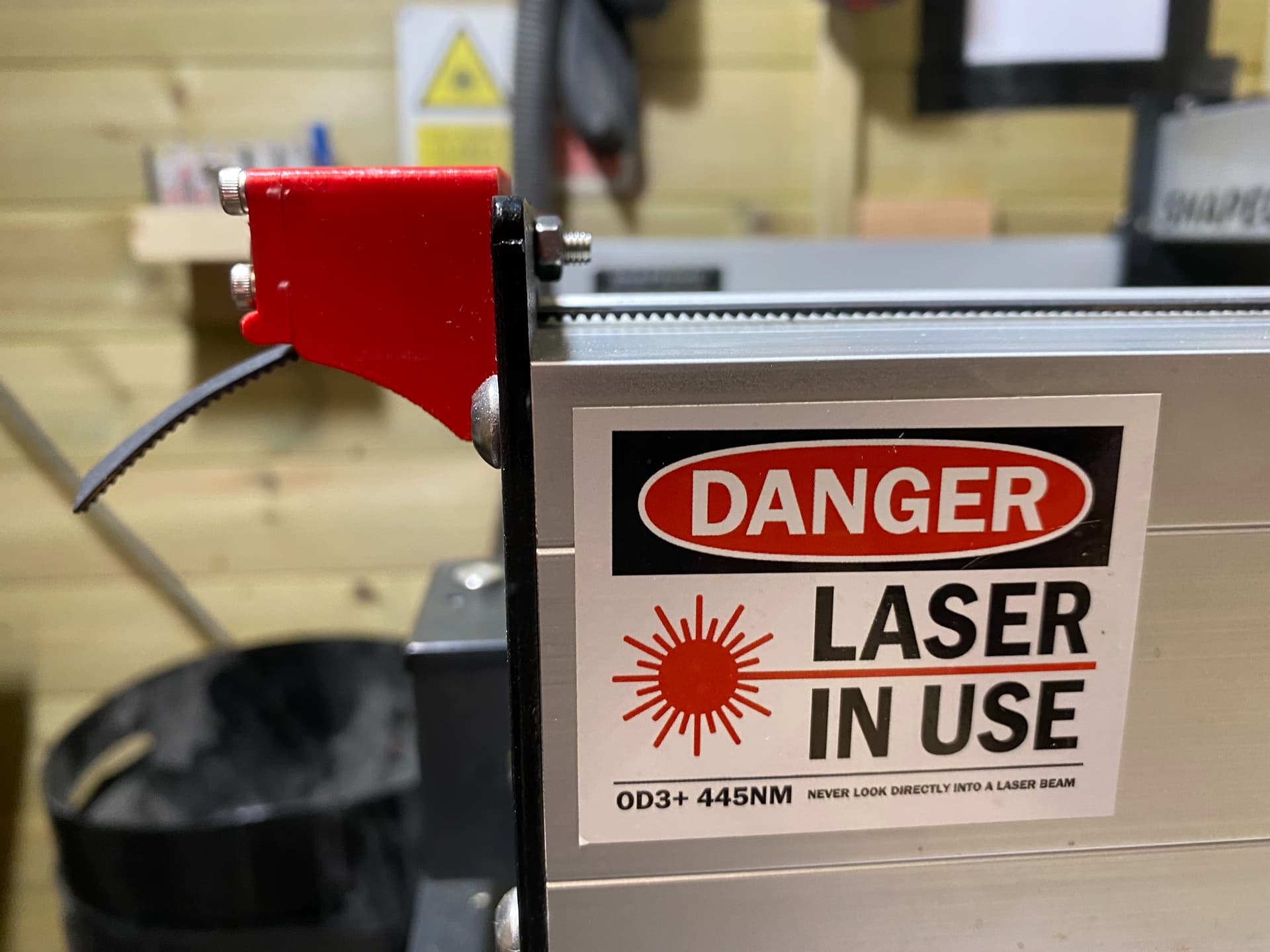
EDIT: Just to note that the laser label is unhelpful. I use safety glasses with an OD rating of 5.

2 Likes

@jepho Excellent write up. Thank you, Jeffrey.

With very few exceptions, the projects that I am doing are wood. Some acrylic, some aluminum. An aluminum “spoil board”, for my usage would not be cost beneficial. I wholeheartedly agree that MDF spoil boards have their limitations when it comes to the dimensional accuracy of my projects. If more of my projects were in metal rather than wood, I would likely look to a set up similar to yours to achieve greater precision. With wood, though, I would respectfully submit that dimensional changes in my spoil board - particularly if I surface it at regular intervals - are much less a factor in the final accuracy of my project than the movement of the project material itself. Between the movement caused by removing stresses from one side of a piece of material and not the other and dimensional changes brought about by humidity and temperature changes, for me, at least, the stability of my MDF spoil board is the least of my concerns.

All that said, I believe that a very big benefit to your set up for any one is the work holding capabilities. Again, for me, it would simply not be cost beneficial - particularly when I would need to cover an area more than 3X the size of the Shapeoko plate. However, it sure looks like an excellent set up.

Thanks again for your detailed write up. It gives lots of food for thought.

Thank you for the compliment, Grant. It is very much appreciated. I suppose that my frustration began when my CNC machine was not an out of the box success. I had no idea just how many variables could be introduced by the user, the stock, the cutters and the techniques used, along with the general approach to CNC use. The end result was when I cut a 50mm square shape, I found that, on measurement, it was 49.8mm from one corner to its adjacent one. On the other end it would measure 51.3 across the square. I thought that needed fixing because I believe in the old carpenter’s adage that if you start square, you will end square.

Because I could see so many issues with the assembly, I started there and disassembled the machine completely. My new assembly was much more carefully completed. Then the issue of MDF spoilboards came to the fore. I now have a much better appreciation of the skills one must bring to the use of a CNC machine and (for me) the fitting of the. SMW fixture tooling plate was a revelation as a fixed baseboard. Work-holding was easy and repeatable and thinking about the squareness of the machine made me seek a better belt tensioning solution. All of the other variables, feeds and speeds, cutter choices, and machining strategies are a part of the overall picture.

I am happy with the machine now and along with the laser, it can machine all that my heart desires. Had I not become so frustrated early on, I may never have gone this route. I have left Carbide Create behind because it is not well written. It may be relatively capable but it does not obey many of the standard conventions for design work. For free software, I accept that Carbide 3D are never going to fix it.

I was up until very recently using Carbide Motion, UGS, CNCjs and Meshcam. None of the software appealed to my inbuilt sense of ease of use. I have had gSender on my computer for 24 hours and I have added a tool length Macro (thanks @NeilFerreri) and the interface is clean and immediately accessible. I will likely stick with gSender after I have ironed out my usage methods.

2 Likes

^ weeks to assemble? Serious? OMG. That alone would have made me burn it.

1 Like

One of the staff claimed the machine needed just 30 minutes to assemble. Many people who had taken between 2 and 8 hours thought they were slow and inadequate in some untold manner. I thought I was being very careful taking three days to build and check everything. I ran the ‘hello world’ test successfully and I was happy that a message scribbled by the machine with a Sharpie was conclusive proof that the machine was properly assembled! :rofl:

The illustrated assembly instruction manual looked (at first sight) to be very comprehensive. I blindly followed it but it had nothing to say about all of the threads that had been painted in the manufacturing process. It also had nothing to say about the angled extrusion end (oversized) nor the difficulty of threading the bolts which held the extrusions to the ends of the framework. The threads inside the corners of the extrusions were provided with around 25% of the bolt hole missing!

It was a manufacturing decision not to weld some threaded tube in situ but to thread a hole that was only 3/4 of the material required to complete a tube to thread and it was incapable of holding the extrusion square. The addition of a pair of diametrically opposed index pins to locate the extrusion ends would have helped. Full cap headed hex bolts would have helped too, instead of the button-headed hex bolts. All of the foregoing is to underline that the machine could not be assembled according to the instructions for assembly, without a fair bit of adjustment.

Adjustments included running a tap through every threaded hole to removed the paint which stopped the bolt from being screwed into the threaded bolt hole. I then filed the excess material of one of the extrusion ends and squared it as best as possible by hand. In the event is still required a 0.005" shim to compensate for the irregularities that a hand finish metal surface will often produce. Screwing the end frame work to the extrusions was a nightmare. It should have been easy to place four screws to secure the extrusion to the frame but the missing 25% of the hole and a single start thread on the bolt, made this task needlessly difficult and frustrating.

When all was assembled and I thought it good, I had believed the Sharpie test was a good indication of perfection in building the machine. The first surfacing of a spoilboard showed me huge tramming errors in two planes and the X rail did not traverse the Y rails evenly. It displayed a difference gap of around 4mm between one side of the X rail hitting the end stop and the other. I still was treating the machine like an appliance rather than an engineering tool. I tried to tram it (quite unsuccessfully) and then settled down to list all that was wrong with the current assembly. This occupied some time because I had no idea about what I did not know. By asking a lot of questions on the forum and reading a huge amount from many other sources, I became more aware of why my machine sucked rocks.

I decide upon a strip and reassembly about 6 weeks into my ownership. Armed with better knowledge, I was able to assemble the machine so it was actually square and the first surface job that came from my machine demonstrated that tramming was not required. The 6 weeks I took over the assembly was repaid in that moment alone. I created an indexable MDF spoilboard and used that successfully for a couple of months but then I wanted to address some work-holding issues. The fixture tooling plate was my solution and it increased my machine rigidity and work-holding capabilities. After modifying the belt tensioning system, I have a machine that gives me reasonable accurate results.

TLDR: Surely the start of the six weeks required to assemble a single CNC machine derives from buyer (me) not knowing enough to get the best out of the machine. The manufacturer did not provide any test file of known dimensions so that when cut, the user could discuss the carved object if the work fell outside of the intended parameters.

EDIT: Spellings and content

2 Likes