[content removed by author]
Have you got access to a multi meter?
If so, did you check the output voltage on your power supply? Maybe that end got damaged when the board tried to make a break for it …
Was the equipment powered up when the board fell? I don’t know about the particular controller you have but maybe there is a fuse that blew? Maybe there is a blown fuse in the power supply?
So many possible causes …
1 Like
[content removed by author]
6 to 7 INCHES ??? Soft-ish landing ???Power was off ??? Sounds to me like there is some really really stupid oversight happening somewhere because none of this raises any red flags for damage. Unfortunately, I am out of brilliant (or stupid) ideas as to what it could be … sorry!
I would suggest it’s time to see if Sienci might have a suggestion.
Good luck !
1 Like
Hey Blunderpunk,
I have an LB and always have been looking for an excu.. moment to open it.. clean it out. You have provided me with that and so I thank you. Since I have it open I might as well take the time to provide you with some KGB data and measurements.
I too can’t figure out how to find the LB schematics in a usefull way and if some siencitist reads this, can you please provide some hints into howto obtain them. The zipfile provided doesn’t seem to contain them or it’s beyond me to find them, Pleas assist- nudge, kick me in the right direction.
However, we don’t need schematics when we have a KGB at our disposal. Now that I have mine free of its cage.. we do. -yayyy-
The next picture I put up is including DC voltage measurements between the GND input and the components between +24V input ending at the power led (insert). You say no powerled, so the problem might be found between 24V input and powerled, so I concentrated on that section specificly. I included the measurements for the LM317T just for lols and to have them, because why not.
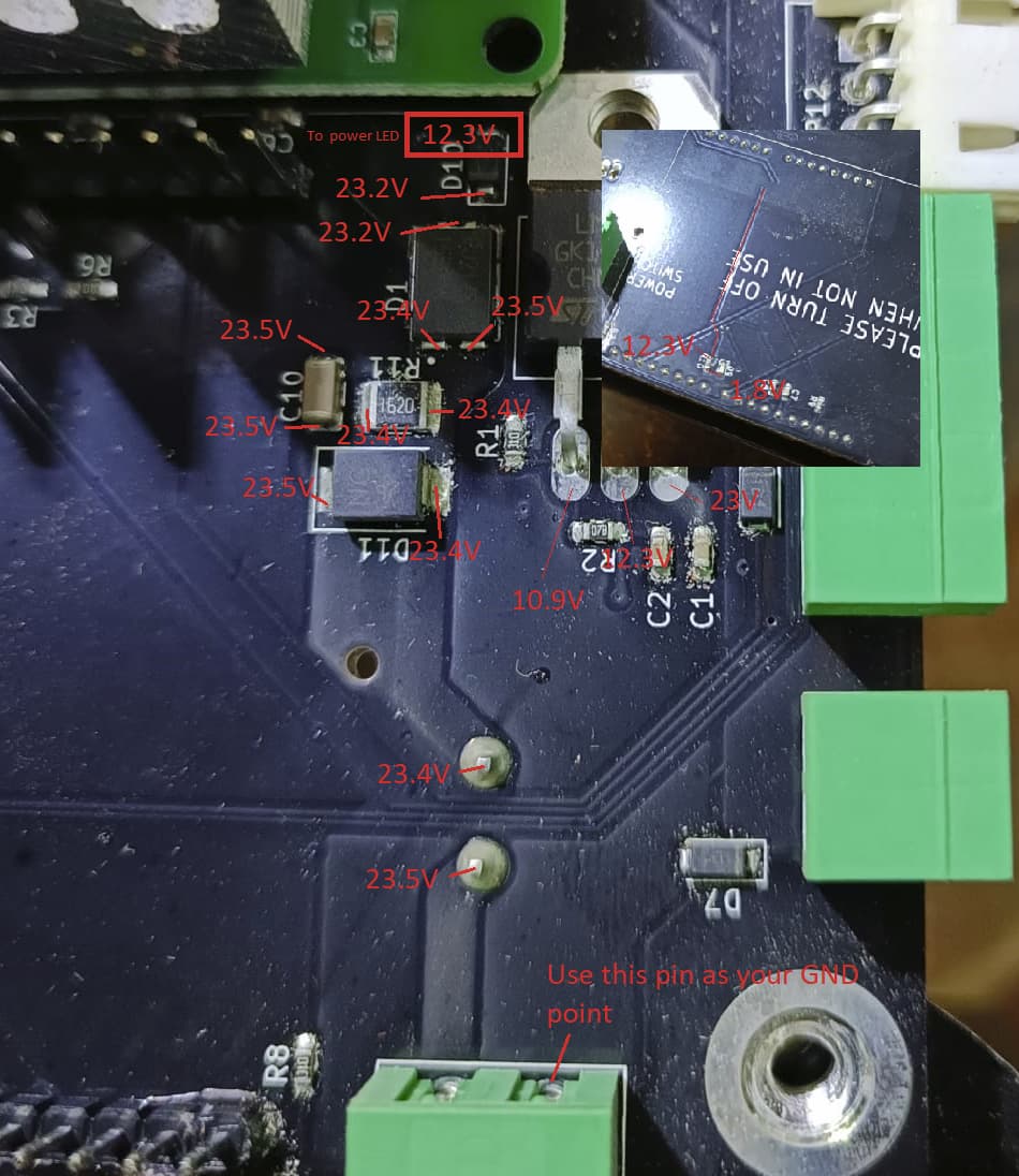
I have disconnected everything from the board except power supply (obviously), e-stop button.
I have removed the arduino and I suggest you do the same. The GND to measure comes directly from the power connector. Though most PCBs have their assembly-points included in the GND circuit, the Longboard does not. (At least, not the input GND.)
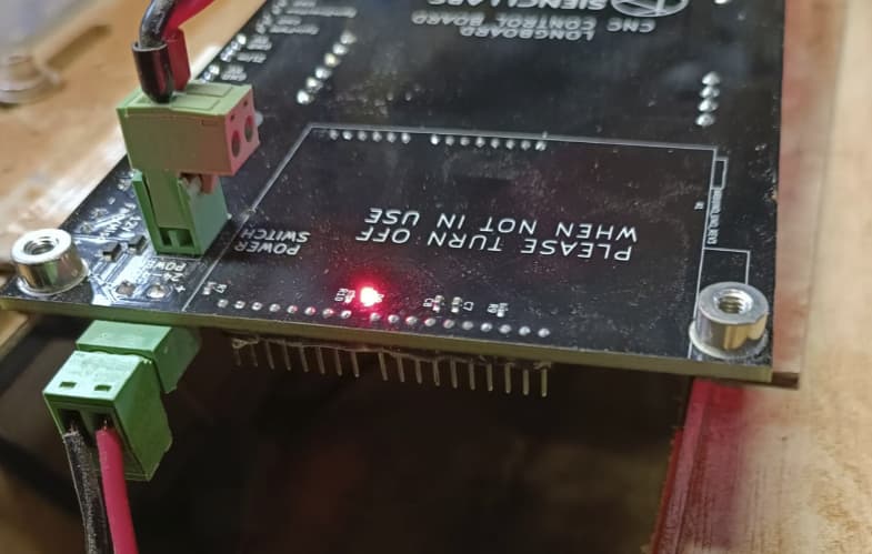
This is how a stripped down longboard looks like powered up:
Let me know if you want other measurements to be done.
[content removed by author]
1 Like
If you use you meter at the gnd pin and you get no voltage readings them make sure you have continuity between the gound pin connector and the ground plane. Also it would be a good ideal to check continuity between the positive pin and the first place that spamming eddie have you check for voltage. Im thinking if the fall broke the connector it may have a hairline crack in the board around that area. Just a quick wag as to my thoughts…
[content removed by author]
2 Likes