I am about to go to #3 of my spoil board, Longmill 30X30. I will be going to the T Tracks and strips of MDF this time. While in this process I realized my machine is out of square a bit and using this gentleman’s process CLICK I have a couple of questions.
I didn’t realize it was out of square until I manually jogged and machined the Y axis as in the video, followed by the X axis, when I used a square against the machine Y axis strip I noticed the discrepancy, so I removed the screws on the right side and moved that to the rear to adjust it about an inch. I don’t know why everything has worked so well without me noticing and completing so many projects.
When I go to my machine limits I measure 31 1/8" Wide X 33 1/4" Deep. If I build my new spoil board like the guy above, do I put those dimensions, my measurements into the surfacing program using a 22mm Surfacing bit, I do not want any kind of a pocket.
I built my spoil board to the machine limits meaning the largest rectangle that a v-bit could reach with it’s point. It’s no problem to surface it as the 22mm bit gives you 11mm off the spoil board that you can reach so the won’t be any pocket. I’m pretty sure, but not positive, that you can just enter the exact dimensions into gSender’s surface program. Worst case is it will miss a little bit in the 4 corners and then you will know that you have to oversize it a bit.
Edit: Forgot to mention that if you have the limit sensors installed you should disable them and soft limits before surfacing. I remove the X and Y sensors when I surface so there is no chance of crashing into them.
Thanks Michael, I understand this seems so basic, but I have bee using the Longmill for nearly three years and I always thought to do a pure 30X30 but the machine actually goes outside that so got me to thinking and searching, I know with the dust boot bracket I will loose a bit on the X Axis, so I wonder how I compensate for that also. So at the machine limits X & Y, that would be 790.575 mm X 844.55 MM, not sure if it will surface that area. 30" = 762mm so 762 + 11 mm= 773 still shy of the limits. I am wondering if I should pull the fence on the X&Y in 2" (50.8mm) to make this work.
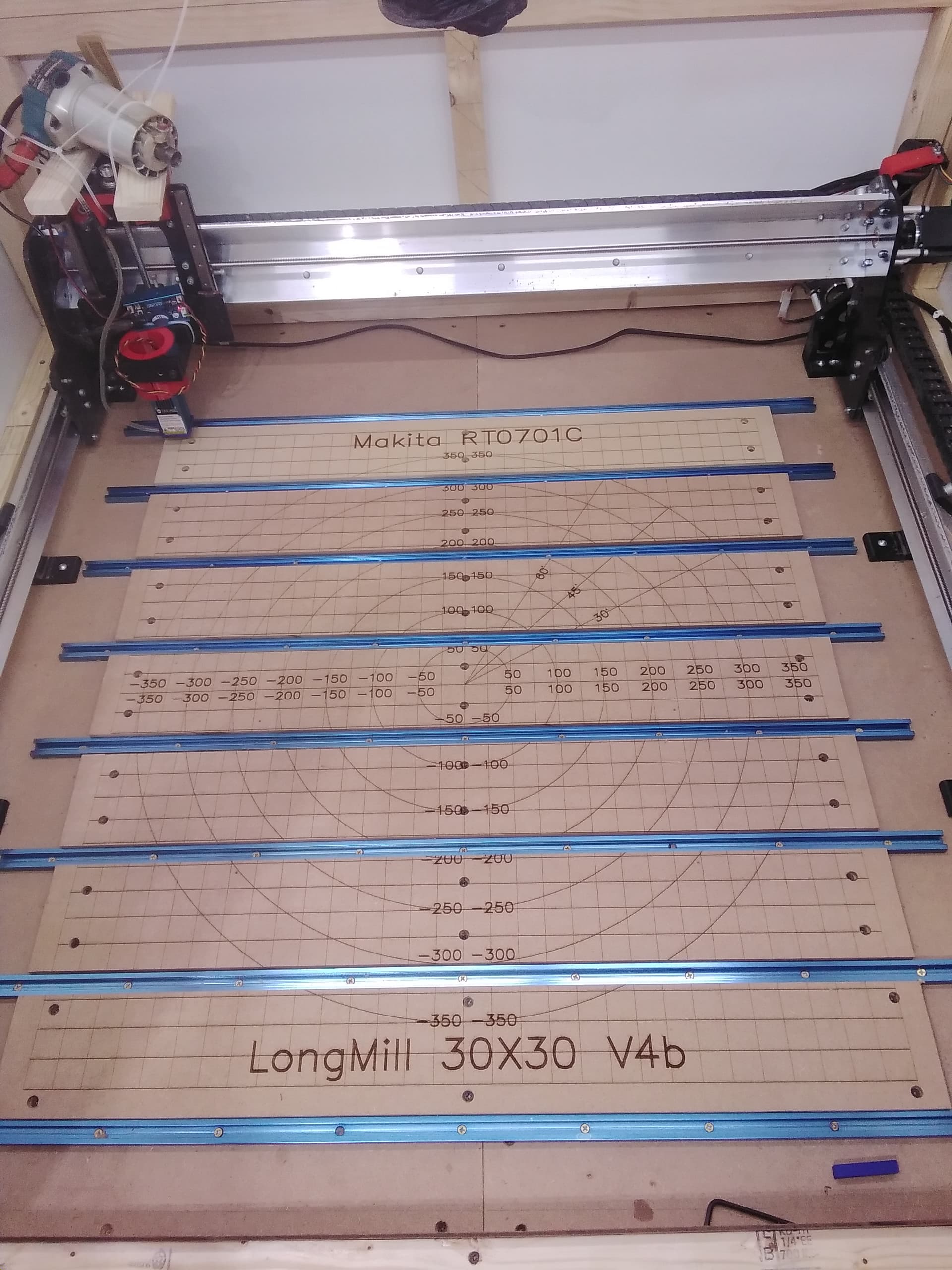
I measured my spoil board and it is 795mm X 840mm and I can surface it fine. I chose to make the spoil board as wide as I could even though I can’t reach all of it with the dust shoe on. I don’t use the dust shoe when I resurface. I just wanted all the room I could get in case I need it and if the job is that wide I just won’t use the shoe for that job. So far I haven’t needed all the width but it’s nice to have IMHO.
Here is a photo of my spoil board. After my last resurface I used my laser to make a grid, 25mm squares, and it’s really nice for placing things square. I don’t usually mount my laser the way it is in the photo but I had to do that setup so that the laser could reach the same area as the router.
Edit: When I remove the dust shoe to resurface I also remove the bracket to gain that space back. It’s an extra step but I don’t resurface that often since I started doing all my through cuts referenced from the spoil board.
Thanks Michael, I never thought about laying the T Tracks om the X, looks cool! That answered my question about surfacing mine at 790 X 844.55. I would never carve anything at that size, just attempting to get my machine as usable as possible.
Please explain that to me, in V Carve I set the thickness of the material, then when creating the tool path I go slightly over (deeper) thus always messing up my spoil board on cut throughs
@gwilki linked this video awhile back and it helped me to not ruin my spoil board. Basically as the video says if your thickness is 19mm you set the bit so it just touches the spoil board and then in gSender you click on the Z number and enter -19mm and hit enter. Then when you cut through it will either cut all the way through or just leave like a sheet of paper thickness to clean up.
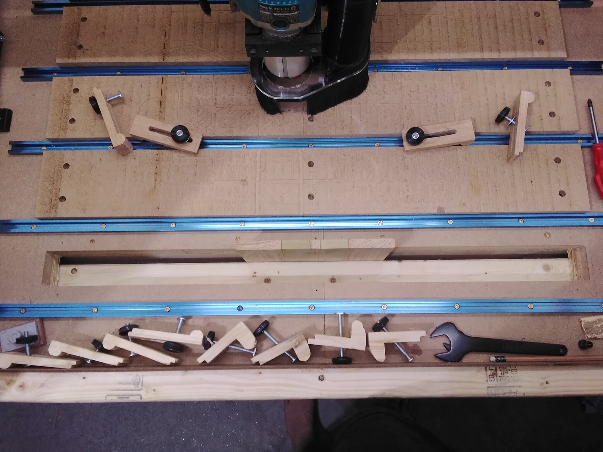
I did them on the X because I have a hole under the closest one that I use to clamp material vertically for doing joinery, dovetails and box joints. I have to remove the first section of spoil board to use it. Anyway that’s why they are on the X but I like it that way because it seems easier to slide in clamps, don’t have to reach the back or slide the clamp into position before placing the stock.
Edit: Add photo of vertically mounted board. This was before I learned how to not ruin my spoil board.
That method looks good to me. Using the story stick seems much better than using a tape measure to me because it should be easier to make sure it’s in the same spot each time.
When I installed my machine I just used a framing square to mark the table with 2 lines making a L shape. I then fastened the front left foot so it was on both lines then I fastened the left rear on the line and finally the 2 inner supports for the left side. Then with the gantry to the front I fastened the right foot on the line then moved the gantry to the back and fastened the back right foot where it was and then the 2 right supports. According to the tool in gSender I’m within a mm and I’m alright with that.
The problem I have is it’s hard to move the machine 1mm because the screw will just go into the same hole and pull it back to where is was. Maybe there is a trick to doing that but I don’t know it.
@Michael Maybe I am over thinking the process, but my wife and I are entering the arts/crafts show option and the more one thinks of doing mass production 10+ the more I think about about repeatable accuracy. We have already been pleased with our design completions and sales so looking forward trying to achieve the best repeatable accuracy. We do resin wood composites and want to do more.
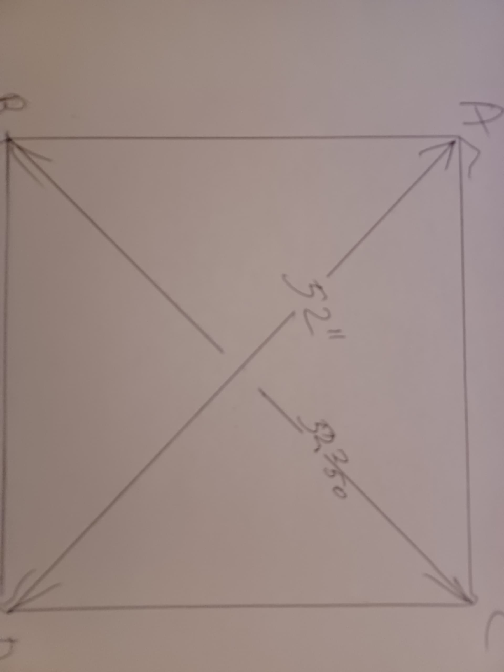
The video is very good, but gSender has a built in calibration module that will accomplish the same thing, with equal or better accuracy and much less work. I suggest that, when you use the calibration module, jog the machine 20" in X, 15" in Y. The distance between the end points should be 25". You can go bigger, but going smaller will result in less accuracy, IMHO.
As for the problem of moving the rails so slightly that the screws fall into the same holes, the solution is to mount the feet on strips of mdf. You cut slots in the strip and mount them to the table with through bolts. You just snug up the bolts and tap the strips of MDF until everthing is square. Then, tighten down the bolts. You will get extreme accuracy this way. This has been discussed on the forum before.
PITA but I use the dowel trick. Remove anything in the way, drill a dowel hole in the screw hole, glue in dowel, cut off dowel and sand smooth. No more hole. I just use a smooth dowel, not the fancy ones with the built in glue grooves.
@RickW, thanks for the suggestion, I have employed dowels for other projects in the past and may do this now…
Looking at my setup I notice the motors for the Y Axis hang off the table a bit, so I can undo all the screws and move it forward and drill all new holes, easier than gluing dowels.
Guessing most folks find all this striving for perfection a waste of time, but I just want a system that is easy to replace and when using threaded inserts to mount the mdf strips everything needs to be pretty accurate. I Plan to make a jig so I can replicate the strips, so if the machine itself is out of square the jig won’t work , thus my effort to get it mechanically square as best I can. It’s more of a long term maintenance issue than a carving issue.