I have recently added the vortex rotary to my Altmill 4x4. While it seems to work relatively well, I cannot seem to get it to turn a piece with a center through hole exactly centered.
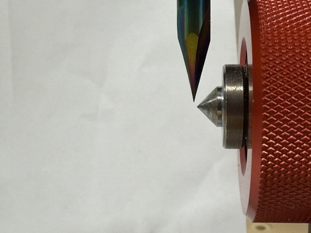
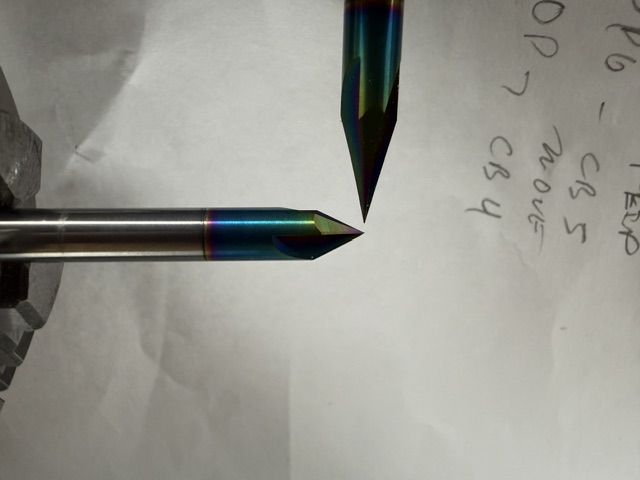
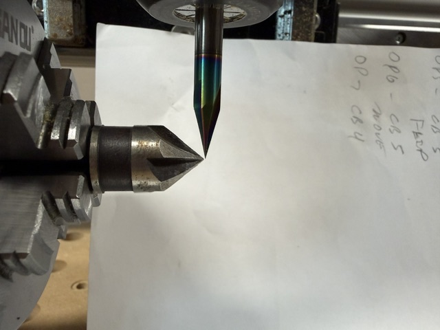
I have checked that the X and Z axis are exactly zeroed and aligned using a fine tipped carving bit.
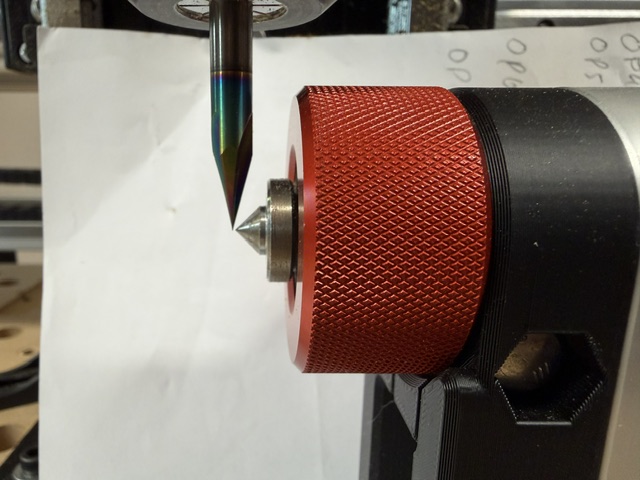
I have noticed that the chuck seems to have a bit of runout and the tail stock seems to tilt up and back when tightening it up to secure it.
Has anyone else had this issue and could provide me some advice on how to remedy this issue?
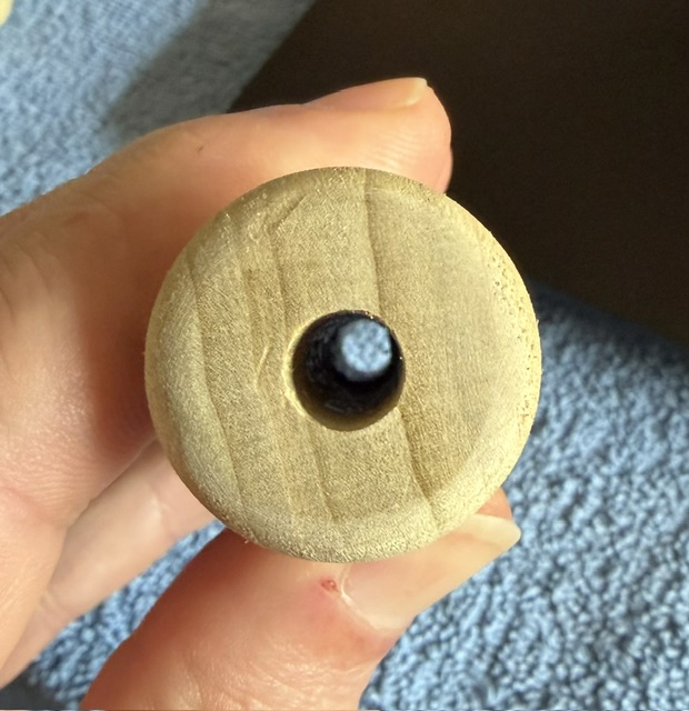
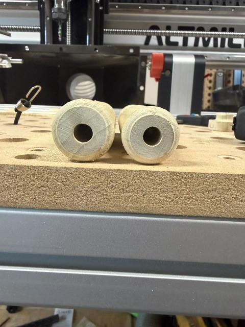
Just for clarification, I predrilled the through hole so that I could then center that hole on the rotary.
Hopefully that makes sense.
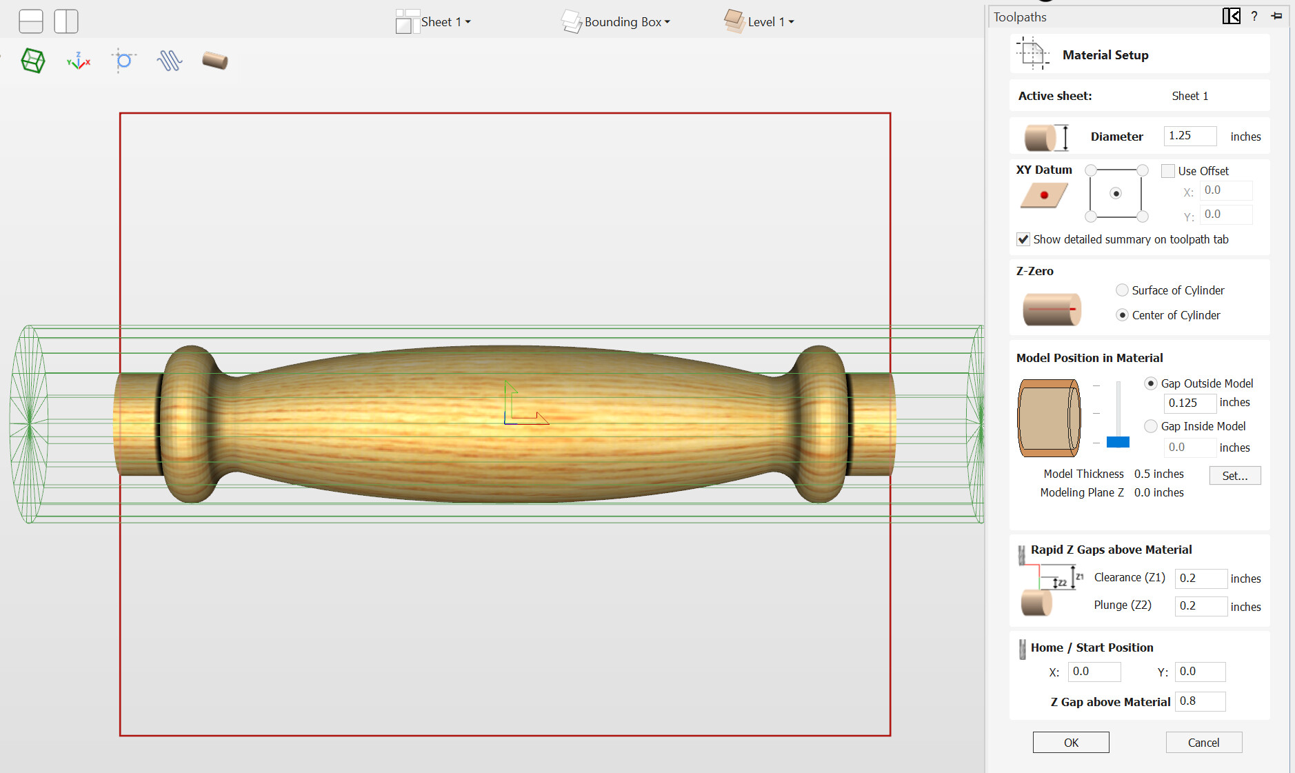
Seems to me that even if the hole I drilled was not exactly in the center of the stock that as long as the carve is inside of the stock diameter (which it is - stock is 1.25" model is 1’) then the hole should be exactly centered after the carve.
@cncConfusion As long as the bolt is running true, your setup should work. You’ve said that X and Z are set. Does this mean that your Vortex runs parallel to the Y rail?
The chuck should not have any visible runout. Make sure that, when the jaws are fully closed, that the meet in the exact centre. The can be off quite easily.
I’ve done many pieces on the Vortex and some pens, which require a fair degree of precision. I’ve never had an off-centre issue.
ps. I forgot to ask how you are designing your piece and if it is a 3D model, how you are centering it in the material.
@cncConfusion I think we may be talking at cross purposes. If your Vortex is mounted on the table parallel to the X rail, then you set Y0 and Z0 using gSender’s probe module. You set X0 manually by jogging in X to wherever you want to start your cut.
Is this what you are doing, or is your Vortex mounted parallel to the Y rail?
@cncConfusion No worries. The usual set up is to have the Vortex at the front of the table, running parallel with the X rail. There is no rule, though.
I’ll be interested to look at your pics to see if we can figure out what’s going wrong. It’s likely something simple.
@cncConfusion Before going any further, please keep in mind that I am not Sienci tech support. I’ll do all I can, but you may need to open a support ticket in the end.
It looks like Z0 is off equally at both the headstock and tailstock ends, correct? So, that would rule out that the Vortex is slanted. No real help. Just an observation.
I assume that you are setting Z0 using the probing function in gSender. Correct?
You are using the stock chuck from Sienci?
What bit are you using to set Z0?
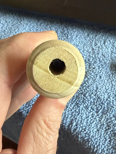
I would try setting Z0 manually and rounding a scrap piece of material around a drilled hole to confirm that the issue is Z0 being off using the probe.
@gwilki I totally understand that you are just here to try and help my confused a$$..
That being said, your are a f’ing genius!
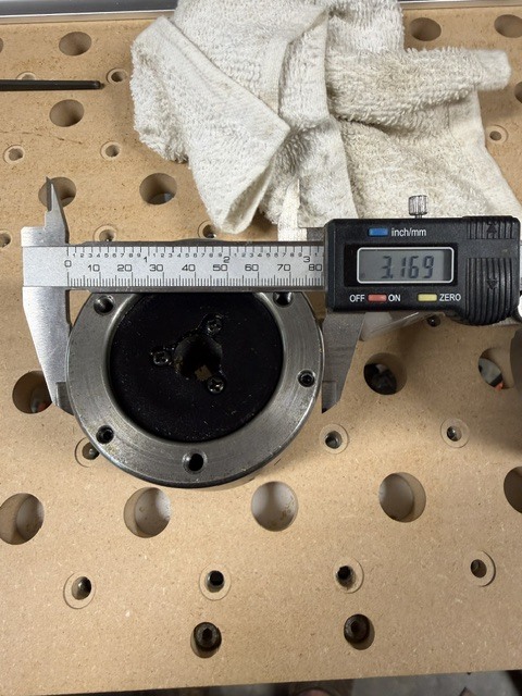
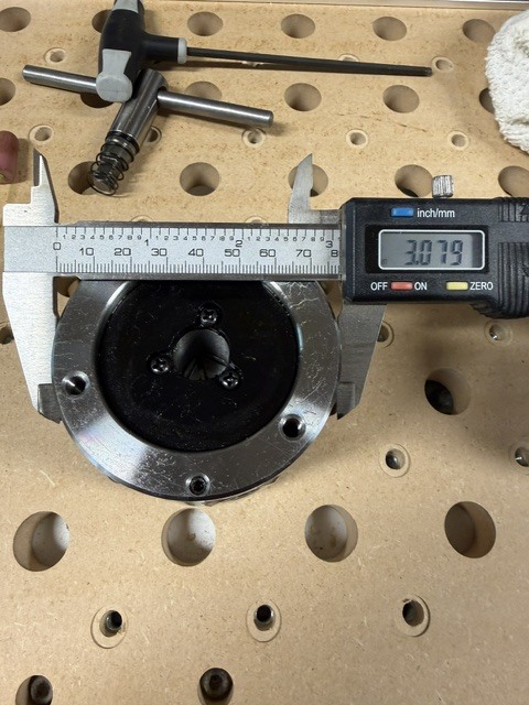
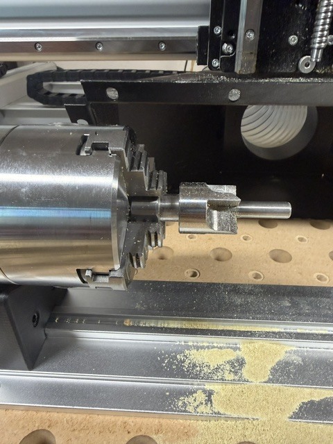
No I was not using the stock chuck, I had switched it to a 3 jaw self centering one for ease of centering materials. I did not think about the specs being slightly different on the OD of the chuck.
So yes, there is a difference .09 so half that is .045 which basically exactly how much it seems to be off!!
For the purpose of the test that I attached pictures of, I used that same bit to set the Y and Z zero.
Still seems weird though that if the program is auto detecting the zero that it would matter, yes I use the X and Y rotary zero functions in the rotary tab.
Here are the pictures of the chucks, bigger one is the stock 4 jaw.
I will put the 4 jaw back on there and test the z again and run another handle off as a test with the new center drive that should be showing up today and see what happens.
Thanks for all your time and patience helping me figure this out!!
@cncConfusion You’re welcome. I’m sure that is the issue. gSender computes where the Z centre point is based on the height of the stock chuck from that centre. It uses a hard coded distance. If you change the distance by using a chuck of a different diameter, gSender does not accommodate that difference.
Unlike the touchplate module in gSender, I don’t believe that there is a setting that you can change to reflect a different chuck size. I can’t tell which chuck is smaller. If it is your new chuck, you could always shim it up with metal foil tape of something. If your new chuck is larger - never mind.
That seems like an easy fix for gSender to at least provide user ability to change that value. It is common on lathes for people to have different chucks then what comes with your lathe.
@DavidB there may be a way to adjust that but I am too new to this software to know for sure. Hopefully someone here knows more and if not I will reach out to Sienci about it.
@cncConfusion Yes, it would be easy enough to do. Once you know the variance, you could write a simple macro and attach it to one of the buttons on the estop, if you like. It would be the same idea as using a macro to jog the machine to compensate for an offset between the router and the laser, for example. I use a crosshair laser to find XY0 as it’s easier than trying to set it with an end mill (old eyes). Then I simply run a macro that compensates for the offset between the crosshair laser location and the centre of the spindle.
ps. Or, you could shim a spot on the 3-jaw chuck to mimic the diameter of the 4-jaw chuck.