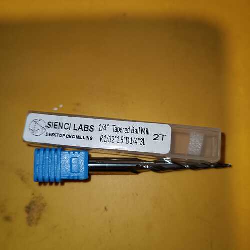
I received a 1/4 roughing bit from Sienci (contest gift). I can’t find their speeds/feeds for this bit. I don’t see it in the chart/doc. anyone use this and what do you set it at for hardwood?
Bookarking this topic for I too have the mysterie bit. Not yet had a need for it so didn’t looked into it yet. A push in the right direction would be great.
The same with the 1/32 tapered endmill.
Usual preface, I’m with PreciseBits. So while I try to only post general information take everything I say with the understanding that I have a bias.
Not sure you are talking about the same bit. But if it’s the long 1.75" length of cut one I went through some of it with a “generic geometry” here:
Not seeing a 1/32" tapered tool in their store. To even take a guess would need to know more like flute count, taper, material, etc. However, one universal thing is that if you are using it for 3d carving with a 8-10% stepover. You can go a pretty fast as the chip thinning means you are actually cutting MUCH less than you think. As an example 50IPM on a 2 flute running at 10KRPM is a 0.0025" chipload (what really matters). However, if you are cutting that with a 8% stepover you would only really be cutting a 0.00136" chipload. Meaning in order to cut the 0.0025" you would need to actually cut at 1.84x or 92IPM.
Hope that’s useful. Let me know if there’s something I can help with.
Correct, it’s not in their store and it’s not something I have a simular one of in my endmill database.. I’m havent used tapered much, so have not looked deeply into them. At the moment I have a job using a tapey but that’s a pretty wide one. I’t a large job and I don’t want to go smaller than 1.5mm tip, 30deg, dual flute set at 10% step-over. I start at 50Ipm to watch initial result and usually step up 20% to 60Ipm.
The 1/32 one is a bit of a mystery. Sienci does not have it in their shop but it seems it will be shortly. I got it send to me as a price. It’s a 3 flute and I guess with a 15deg taper.
The day I have a need for it I’ll prolly look deeper into it, but for now it’s a blinky asset with potential. If you could shine a light on it, that would be awesome. Saves me some deep diving into -there’ll be dragons- waters of unknown depth.
Now going to look at your linked post. Mucho gracias for the info already given.
I can give you a rough idea of how I would go about it. If memory serves, gwilki said in one of my other responses that the LongMill is limited to ~4000mm/m (157IPM). So I would work around that using chipload and a force limits.
Before I get into that though I want to double check a few things.
-
First I’m assuming that you aren’t talking about the endmill in the picture? That one appears only has 2 flutes and from the label I’m assuming a 1/16" tip.
-
Typically tapered carving tools are listed by the half/draft angle and not an included angle like a “V” cutter. Is it a 15° half or included angle? Another way to figure this out is to know the flute length and diameter at the widest fluted section.
-
How deep are you going and are you roughing first?
-
What material?
I’ll go through a couple ways. But I want to make sure I’m hitting something close within that.
Hey TDA,
I went with the label and assumed the 3L ment it was a tripple flute. The 2T should have given it away.
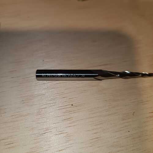
I looked at the bit a wee closer and it turns out the bit is marked with the info in mm. Being from metricland, that I can work with. Turns out the 3 is the length of the tbn in inches.
0.79375 is 0.03125inch and that turns out to be 1/32.
Angle does not compute for me. My english isn’t good ebnough to wrap my head around what you are saying about it.
I think the widest fluted diameter is 6mm or 0.236inch but its a bit hard to measure precise.
Angle, looking at a bit stated as 30deg, this is a 15.5 deg.
My stock will prolly be a hardwood being, padauk, robinia, azobe or angelim vermelho, thermo ayous (abachi) and for simple p[rojects, red/yellow pine, but I don’t see me using tapers on that.
I do a roughing pass before tapering, pretty rough with a 6mm35 uc. I don’t feel like these tapers can remove much without deflecting, so I keep it conservative again.
Tool:
-
From the laser engraving and label I believe that's a 1/16" ball. The R1/32" and R0.79375 probably mean radius and not the diameter. This tool in the Sienci store has the same laser engraving ([Link](https://sienci.com/product/1-32-radius-tapered-ball-end-mill/)). Picture doesn't match though as the helix is different in the store picture than here, core looks different too.
Taper angles on tools gets weird as they are dependent on the tip and max diameters. Going by the Sienci spec for that tool in their store it says 3.65°. Going by the other specs listed at 0.0625" tip, 1.5" length of cut with the ball, it calculate out to 3.6522°. However, centerless ground blanks are never actually the diameter listed and grinding a flute also reduces it. So realistically it’s probably 3.62°-3.63°. If I use your 6mm number as the max it would be 3.3845°. Those are close enough that you should be good with the 3.65° for most purposes. Worst case is the CAM software will be a bit more conservative in how close it let’s the wider parts of the tool get to the previous cuts.
Short, simplified versions of chipload and surface speed.
-
Chipload is the widest part of the chip taken per flute per revolution. There is a minimum chipload needed to actually cut a chip that is based on tool geometry and the material being cut. Under this you will rub the material out of the way. Rubbing typically produces poor finish and will always increase heat and decrease tool life. Ultimately chipload is probably the MOST important factor in milling.
Surface speed is the speed of the edge of the flutes. The higher this gets the more sear force you have which typically gives a better cut up to the point of failure of the material or tool geometry. Higher surface speed does increase the heat in cut slightly. But by a MUCH lower amount than rubbing will.
Both of those combined are what Feed and Speed are trying to get to. There’s also a few caveats to things like chipload. The most often ignored ones being:
-
Runout, which typically adds and subtracts chipload from different flutes in multi-flute tools.
Cutting less than a 50% stepover will make the chipload smaller (chip thinning).
Acceleration determines how fast you get to your feed and can limit your feed.
Chipload, Surface Speed, Stepovers, etc:
-
There is a feed and speed listed in Sienci's chart for this tool at 3800mm/m (149.6 IPM) and 28,500RPM with an ~5% stepover for finishing. That works out to a raw chipload of 0.066mm / 0.0026". However, at the 5% stepover it would only actually be cutting 0.029mm / 0.0011" chipload after chip thinning. That's on the low side in my opinion especially with this many direction changes.
If it were me I’d be trying to hit a minimum of a 0.038mm / 0.0015" chipload after chip thinning. Ideally closer to 0.051mm / 0.0020" for most of those woods. Part of this depends on tool geometry and material. However, even with REALLY aggressive tool geometry and harder woods the better cuts are going to be on the higher end. The softer the material or less aggressive the tool the larger this number needs to be to actually cut a chip and not just rub the material.
For most of our customers in the industry, this type of tooling in 3d carving of woods and plastics would be at 8% stepover. This is mostly an old rule of thumb number as 10% is typically considered the max you can go to get “smooth” surfaces. However, everything is a spring, so most run at 8% to give margin for deflection and material changes.
Between all of these we have 3 stepover numbers 10%, 8%, and 5%. Those will all produce a different amount of chip thinning. You can find calculators for it but I’ll give a simple way to account for these three. Basically we are going to times our current chipload/feed by a multiplier to get a chip thinning compensated number. For these 3 it’s:
- 1.66x for 10%
1.84x for 8%
2.29x for 5%
Using the data.
-
Okay, so now we need to use all this. For this I'm going to go with that 0.051mm / 0.0020" chipload and the RPM ranges listed for the Makita listed in the Sienci chart. To calculate a feed: Feed = chipload * flutes * RPM. That makes our feeds at a 0.051mm / 0.0020" chipload for those RPMs:
-
28,500 RPM - 2896mm/m / 114IPM
27,000 RPM - 2743mm/m / 108IPM
22,000 RPM - 2235mm/m / 88IPM
17,000 RPM - 1727mm/m / 68IPM
12,000 RPM - 1219mm/m / 48IPM
So depending on our stepover we will have to lower RPM to hit the chipload target. We want to keep the RPM as high as possible though as the higher the RPM the more sear force on the cut. So using the multipliers above that works out to the following RPM and feed for our selected chipload staying under the 4000mm/m max.
-
5% stepover - 17,000 RPM - 3962mm/m / 156IPM
8% stepover - 17,000 RPM - 3183mm/m / 125IPM
10% stepover - 22,000 RPM - 3725mm/m / 147IPM
Those will all product the same chipload and cutting forces after chip thinning (within rounding). If we wanted to do this for another chipload we would repeat from the above changing out the 0.051mm / 0.002" chipload for our new chipload.
Keep in mind that if you are not able to hit these due to too short of segments (lines). You may need to scale the feed and RPM.
Cutting forces:
-
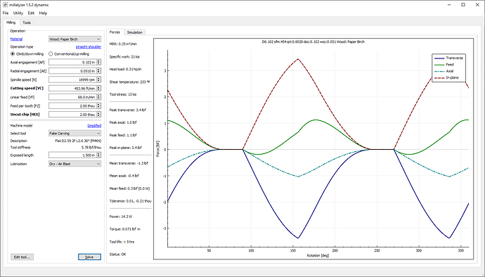
Unlike the 1/4" tool in the other post the forces on this after your roughing are insignificant at these chiploads. Millalyzer doesn't have a calculation for tapered tools. However we can use it to calculate for worse case. For this I'm going to assume that we are leaving 1.3mm from our roughing pass.
I won’t belabor the whole method unless someone asks. But basically I’m going to calculate what the diameter of the bit will be at the 1.3mm we will have left from roughing and also use that for our calculation of the plunge.
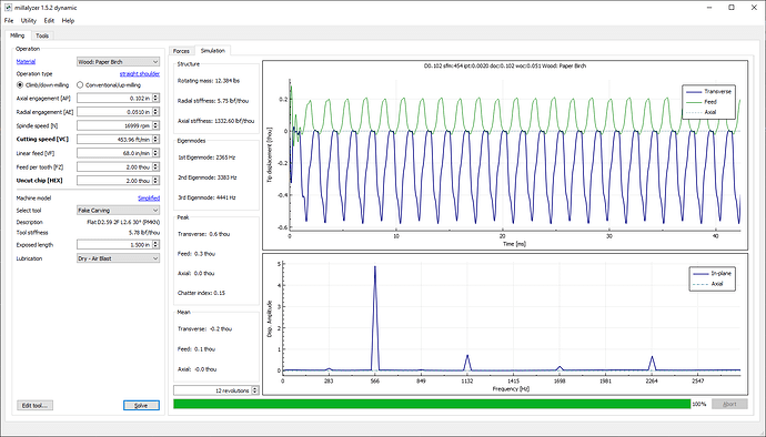
That give us the following for cutting forces and deflection over time mimicking my other post.
Again this is worse case as it’s assuming that we have a much greater engagement time and cubic material removal as it can’t account for the tool getting smaller toward the tip.
Our peak cutting forces here are only 3.4lbf and uses 14.3W. Single rotation deflection is -0.0053mm / -0.00021".
Worst tool deflection in 12 rotations is 0.0152mm / 0.0006".
I’ve been EXTREMELY long winded here so leave it here for now. If you want more information on something let me know. Also, I ran out of time to go over this more than once. So please forgive poorer grammar and the like than usual.
So… back to my original post… ![]() does anyone have the settings for their 1/4" roughing bit? 1/4″ Extra Long Flat Roughing End Mill | Sienci Labs
does anyone have the settings for their 1/4" roughing bit? 1/4″ Extra Long Flat Roughing End Mill | Sienci Labs
It doesn’t appear to be in their charts yet. I could use the 1/4" UC or DC settings, but it looks like this bit could be more aggressive than that.
Hey slovdahl. Sorry about the thread divergence.
It’s partially addressed in my first reply. To summarize it, tools that stick that much out of the collet have to be run less aggressively. They are like for like more prone to deflecting (bending). The only “not like” part I can confirm on them other than the lengths is that they are a chip broken flute. That will “reduce” “some” of the deflection as you are not keeping flute engagement through the whole length (depending on crossover location and chipload). But, it’s not a miracle worker that lets you ignore the rest of the physics. e.g. in that other post’s example, it’s about 3lbf to bend the long tool 0.001" and over 13lbf for the shorter one.
If I look at the feeds and speeds listed for the regular ones in Sienci’s chart, they are conservative. However, in my previous example I had to be much less aggressive to what is listed in that chart for reduced speed to keep the modeled tools deflection reasonable.
Here’s a straight comparison if it helps. Keep in mind for the below that I don’t know the geometry of either tool. I’m working off of a “generic geometry” and “generic carbide grade”. So basically I can’t guarantee anything / use at your own risk.
-
Sienci reduced feed 1/4" UC:
Feed: 1650mm/m (65IPM)
Speed: 12,000 RPM
Chipload: 0.06875mm (0.0027")
Stepover: 2.85mm (0.11") / 45%
Stepdown: 6mm (0.24")
MRR: 43.73 ³mm/m (1.72³in/m)
Per flute MRR: 21.73³mm/m (0.86³in/m)
My calculation:
Feed: 1829mm/m (72IPM)
Speed: 12,000 RPM
Chipload: 0.0508mm (0.002")
Stepover: 3.175mm (.125") / 50%
Stepdown: 2.54mm (0.10")
MRR: 22.86³mm/m (0.90³in/m)
Per flute MRR: 7.62³mm/m 0.030³in/m)
If you are trying to slot with this it gets harder. Forces are functionally cubic material removed per flute per rotation. So while not technically correct, you could double the stepover (slotting) at half the pass depth. It changes some as the helix (flute twist) moves some of the force into the Z. But you are also keeping the tool engaged on the other side of the cut while slotting. You are also breaking the flute engagement with the cross cuts in the flute. So best guess, maybe only an 80-90% reduction of the pass depth.
Hope that’s useful. Let me know if there’s something I can help with. And sorry again for the thread divergence.
Edit: Forgot to mention that this is also all dependent on the material being cut. So the harder the wood the more forces. I used paper birch in the simulation.


