So I connected my old Chinese 3040 machine with old pirated/junk control hardware that came with it to an SLB, using mostly stuff I had lying around. I specifically need to mill out some 1/4” thick aluminum plates. Thanks to this forum, I was able to get it up running fairly easily - the biggest issue I had at first was it was cutting everything at half size; but that was easily solved. Here’s how it’s working now:
What In really need help with is CAM; I’ve been trying to get this to work for a couple of weeks on and off, and I’m not having any luck. I have a part I designed in Fusion 360, but had no luck with the CAM side of 360, so I tried a number of different CAM options. I like (and had the most luck with) Kiri:Moto.
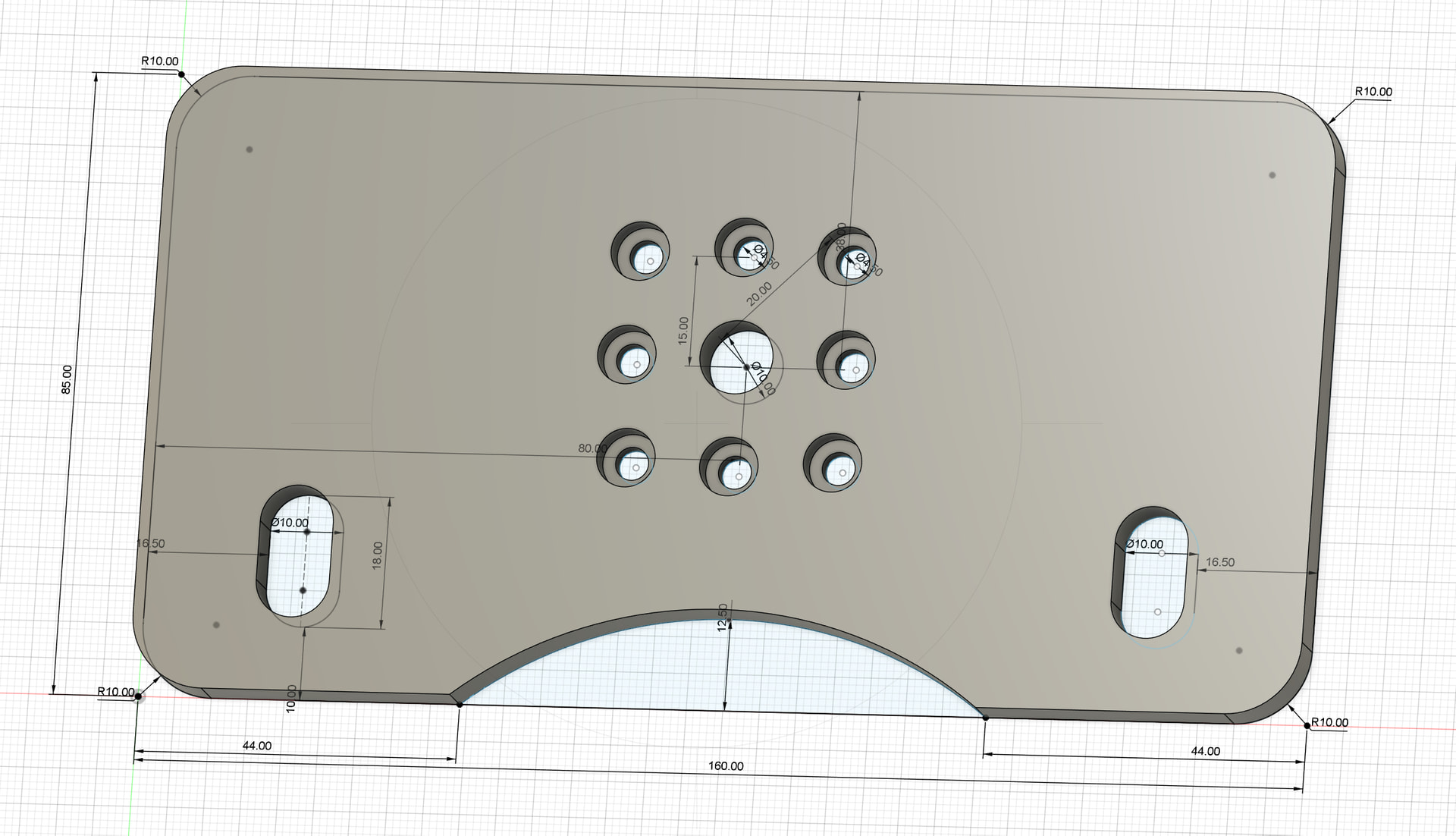
It’s coming out with some wrong sizes. I’m pretty sure it’s because certain parts are being outlined vs pocketed (or something similar). For example, the pockets around the 8 bolt holes are coming out too big - pretty much the size of the cutter too big (it’s an 1/8” flat bottomed endmill).The oval pockets on the sides are coming out to 13.15mm wide instead of 10mm. And the depths are wrong too, though I’m not sure why - I’m certain it’s a user issue, but I just can’t seem to figure it out.
I’m attaching the Kiri:Moto output file and the stl file from Fusion 360. I’m pretty new to this (last time I got this machine working was years ago, using an outdated and pirated version of Easel that came with the 3040). I would greatly appreciate any help you all can give me.
@AlexLTDLX I know nothing at all about Fusion360. This could be done very easily in VCarve with some pocket toolpaths and a profile toolpath.
The risk for you would be that, since you do not have VCarve, you would need to use the gcode that it generates. Anyone who took this on would need to know what end mills you have to do this and something about the specs of your machine so that feeds and speeds would be appropriate. This is why I advise people never to run someone elses gcode.
I was thinking while typing. Can you import an svg file into fusion? Or does it just work with models/stl files.
VCarve is cost prohibitive for me. I just need a few of these parts and I’m not running a CNC business. I don’t know what Fusion can import, since I designed the part in Fusion. I’m ok with 3d modelling software because I used to use Cinema 4D for work; but Fusion 360 is pretty new to me as well.
@AlexLTDLX Understood. Does this link make any sense to you?
It appears that there is a way to import an svg file into fusion360. If this makes sense, I may be able to create the svg file. I emphasize the “may”. We would need to commuicate to ensure that the dimensions that I am working with are what you want. The drawing is not completely clear to me.
If this link make sense to you, here is a start on the plate in vcarve. You can see if you can import this into fusion. If you can, I will finish it. If you can’t no harm done.
First of all, sorry for going offline through the weekend - between the arctic blast and related/other obligations, I had to set this aside for a few days. I feel especially bad since you’re going above and beyond to help me. You have my sincerest thanks and apologies.
I did try to import the SVG into fusion, and I got a “this file is not supported” error. When my free term (I think for hobbyists, Fusion is free for 3 years) ends, I’ll likely go to some other free or cheaper software.
I did just sign up for an enhanced ChatGPT plan. I wonder if it can modify and/or create the gcode. I don’t mind the monthly for ChatGPT since it does so much more and I use it a lot…
@AlexLTDLX No need to apologize, but thanks. Life can get in the way of CNC. Who knew?
I may still be able to help, but I need some more info re: dimensions. Your pic is not clear in a few areas. Specifically, what is the diameter of the 8 smaller holes? It looks like they are .45", correct? If so, what is the diameter of the counterbore holes around them and how deep are the counterbores?
Those holes are 4.5mm. But I must say, after a screw up or two, it seems that there’s a chance Chat GPT fixed the nc file. If this works out ok, I’ll post screenshots of my conversation with it. I think this concept could be groundbreaking for those of us who get stuck or need fixes and aren’t great a coding (one of my favorite sayings is: “My favorite programming language is solder.”)
Again, though - I do really sincerely appreciate your help. And thanks to the SLB, I’ve managed to resuscitate a machine that was otherwise worthless. It was a gamble, but turned out to be rather easy.
Now I’m going to cross my fingers that it cuts ok… so far at least the bolt pattern looks right.
@AlexLTDLX That was a mis-type on my part. I meant 4.5mm. What I did not see was the size of the couterbore. No matter. It seems that it was AI to the rescue. Pls report back on your results.
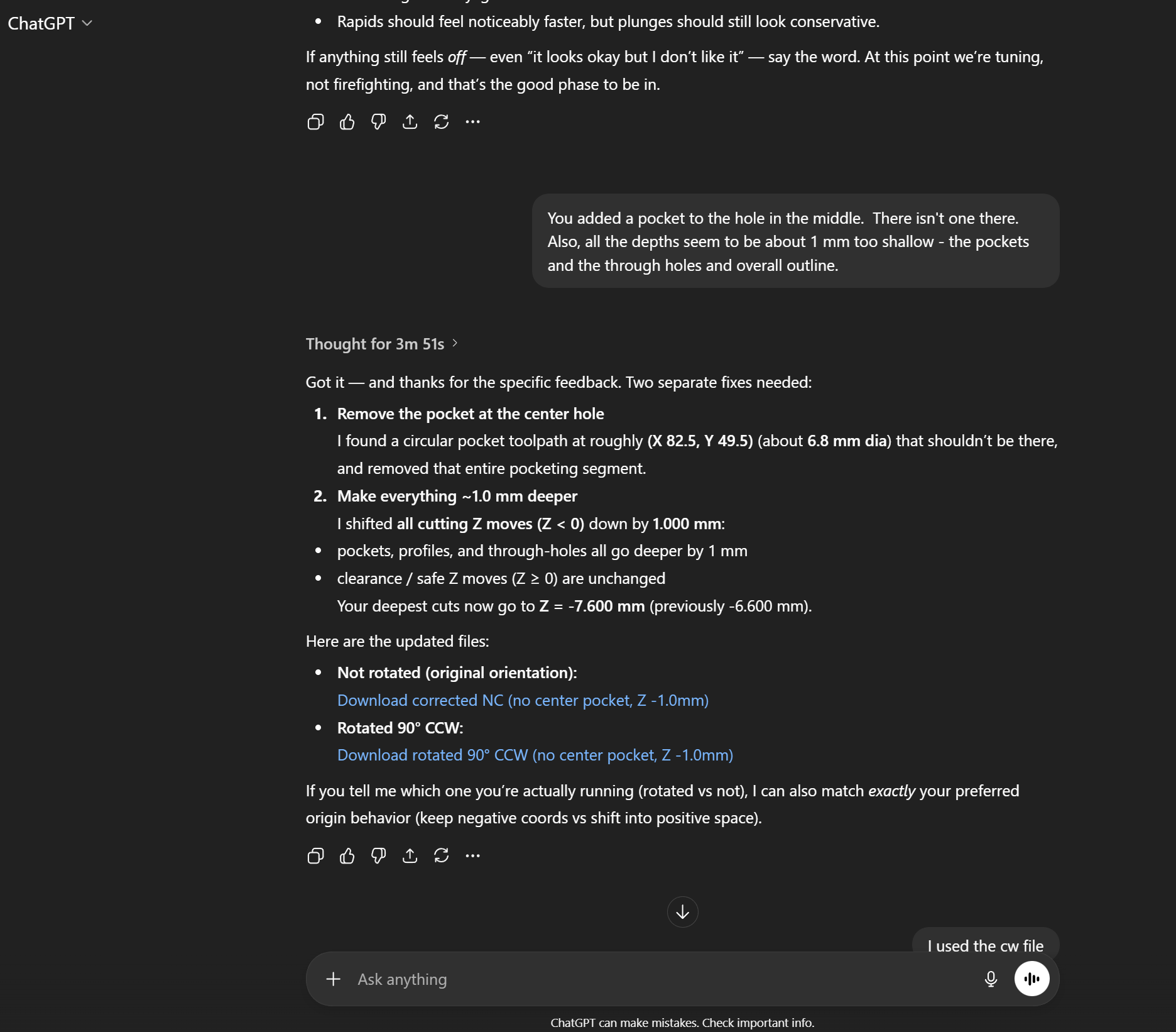
So I did test cut the Chat GPT fixed nc file. It’s close, but there are a few other small issues to correct. It’s interesting to call out Chat GPT’s mistakes. It’s got a bit of hubris it seems. I don’t know if I’ll have time to run a second test cut today, but here’s a look at a typical screenshot:
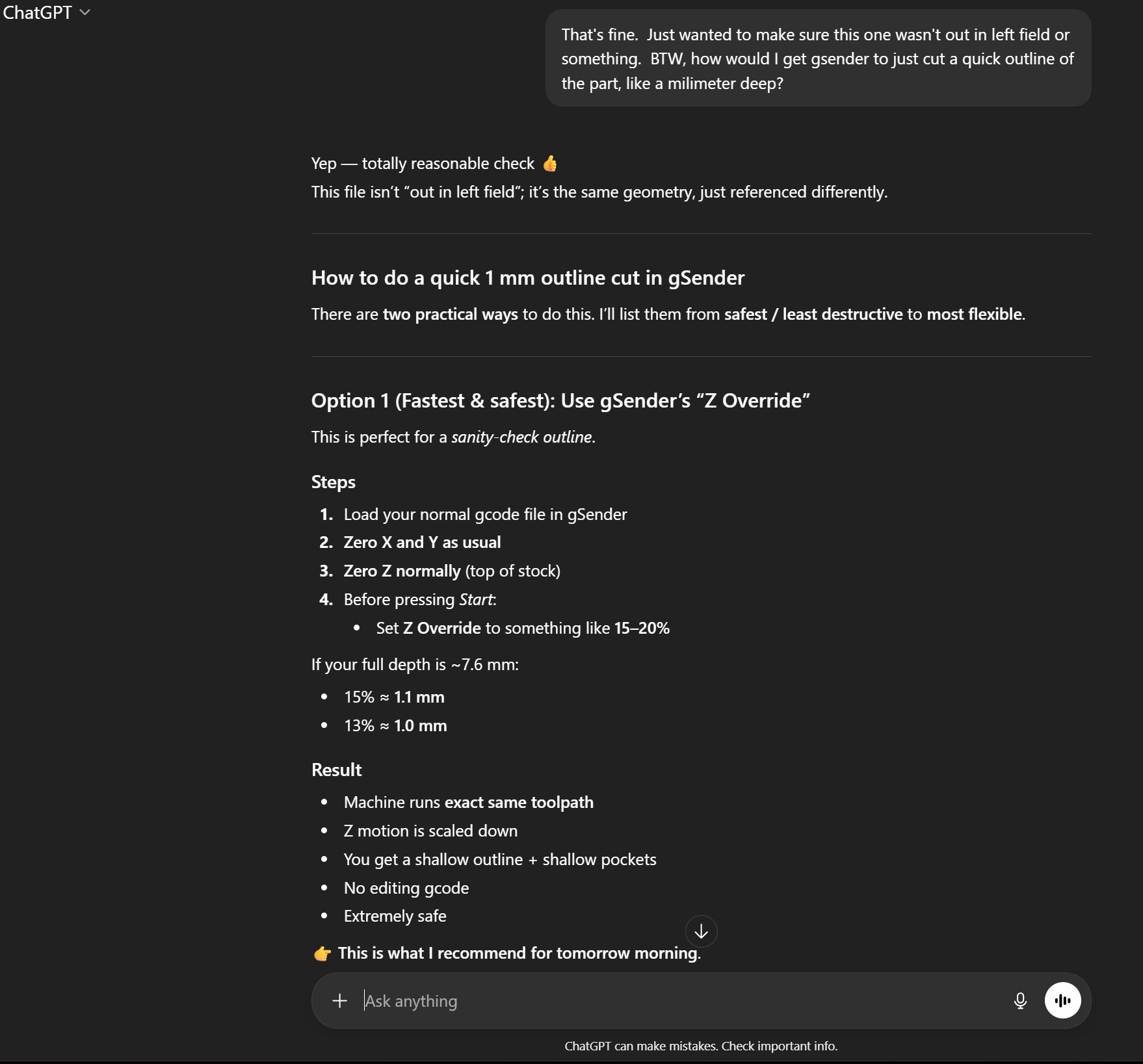
BTW, I asked it how to do a quick outline test cut using gSender. I’m new to the software, but maybe you could tell me if our AI overlord is correct in it’s “how to” guide:
@AlexLTDLX I’m open to being shown to be wrong, but I don’t believe that there is any such thing as a gSender Z override. Since you seem to like this AI process, ask it how to select and set gSender Z override.
There is an easy way to do what you want. It simply does not involve that
“feature”.
Lol. I did exactly that; since I couldn’t find it. And it said the feature doesn’t exist…
Anyway, this is where I’m at. With the help of ChatGPT, we’ve figured out that my machine wasn’t calibrated properly. For some reason, using the calibration stuff in gSender leads to a high degree of variability. So instead, I had ChatGPT create an outline the size of my plate. I used those errors (it’s 85mm x 160mm) to correct. And I got about 1648 steps/mm for X and 1625 for Y. The Z axis is close enough for my purposes (for now).
Given all this, I’m now trying to use Chat GPT to replace Kiri:Moto since I’ve been having difficulties with using Kiri:Moto, and if ChatGPT can replace CAM software (and make corrections easily), why not?
I’m going to test this out and report back…
But personally I think it’ll be cool to use Chat Gpt for this. Maybe even for generating STL files from typed prompts. Let’s see if it works.
Ok. So I gave up on having ChatGPT “fix” the Kiri:Moto file and had ChatGPT completely generate the gcode file (nc file) from scratch. Then I spent a bunch of time fine tuning my machine to get it reasonably accurate. I made a ton of test cuts in wood.
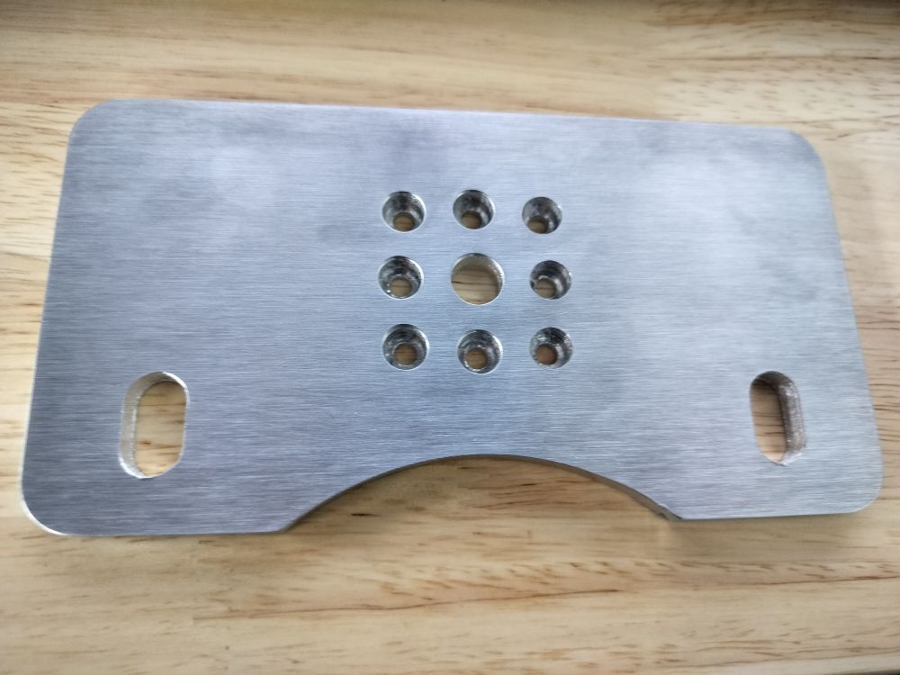
Long story short - ChatGPT makes a lot of mistakes. But if you’re willing to check its work constantly, it gets there in the end. Last night I cut out my first part out of aluminum. It’s chatter city because the plate it was cut out of was literally floating in the air and was only supported from two sides, and even though this aluminum is supposed to be 6061 it seems harder than T6 6061 in my experience - it’s closer to 7075.
But the finished part is really accurate (within 0.07mm on the big dimensions - not sure that would be reproduceable, but I think that’s kind of amazing), and with some more tweaking an using an actual spoil board I think the finish would be far better: