Hey everyone! Shapeoko guy here. I posted this on the other forum, and I thought I’d post it here as it may be of interest to someone:
I’ve been sitting on this post for a while, but I’m pretty excited about it. I know there have been others that have done a rotary axis, and I have always wanted to try it. I finally realized that, with three kids (not counting the SO3), I have no free time. My hopes of DIYing a 4th axis aren’t going to happen. I went with an “off-the-shelf” version, and I couldn’t be happier with the outcome.
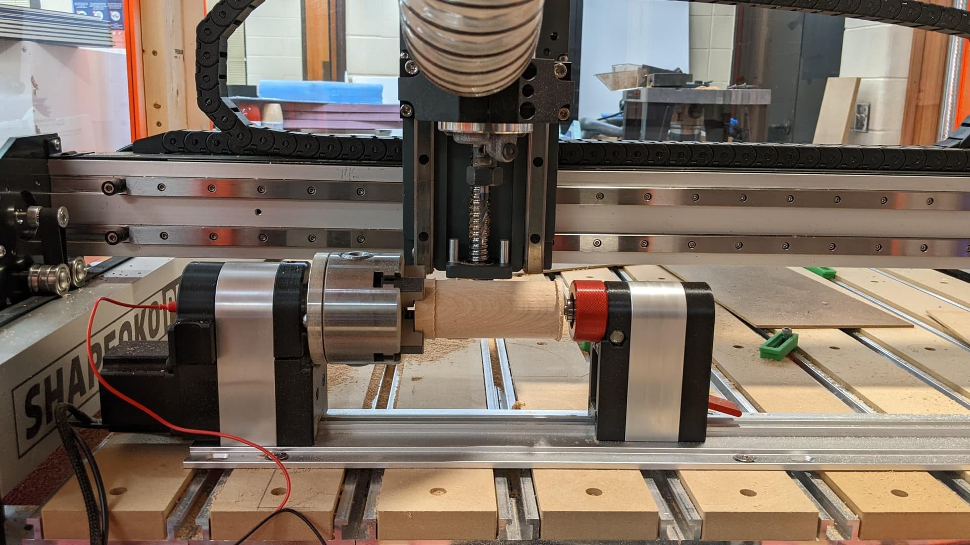
I wanted to share my experience with connecting a Vortex Rotary Axis from Sienci Labs to my trusty Shapeoko Pro. I really didn’t know what it would take to get it going, but I figured it was made for a grbl based machine/controller so it should work, right?
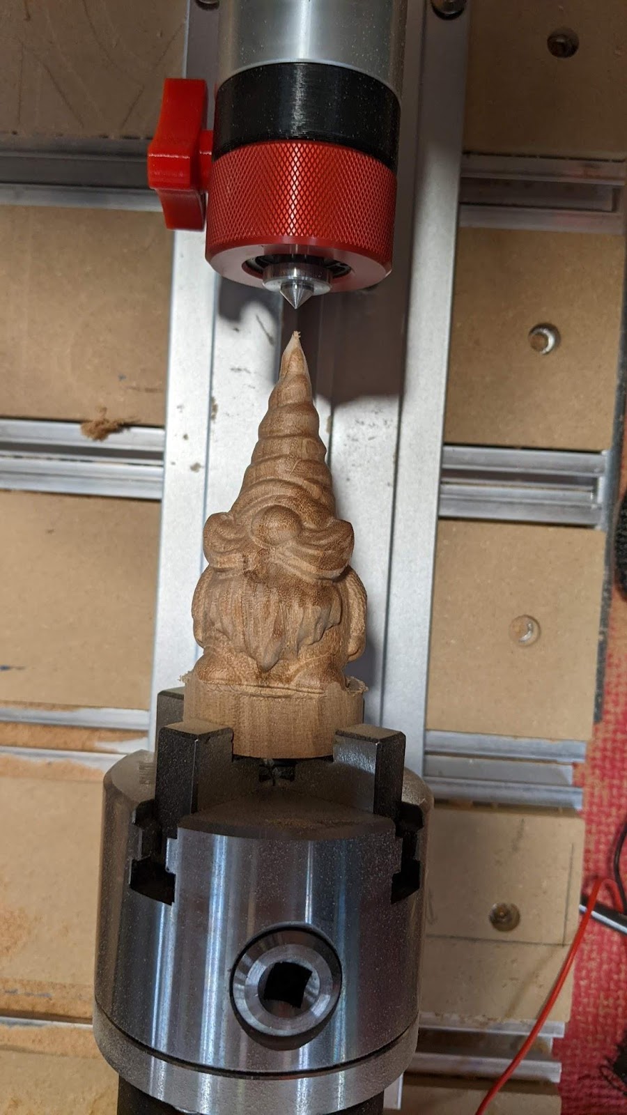
First, a look at the first attempt at a rotary carve:
After getting the Vortex, I was impressed by the simplicity of it all. It’s really just the chuck, tailstock, and a custom extrusion to mount it to. The part that really impressed me were the integrated, 3D printed parts that make homing and probing seamless…more on that later. I was also impressed with the online assembly and getting started documents from Sienci .
It’s really solid and fairly easy to remove and put back in place when going from Rotary to Y.
I fully expected some challenges with the main three being: wiring, aligning it to my X axis, and keeping the Y in place.
The vortex comes with a switch that allows switching from Y to A for rotary jobs, but it simply disconnects the Y motors and connects the rotary (A) motor to the controller. This should only be switched when power is off, by the way. I knew that would not be enough on the Shapeoko Pro (or 3 or 4 or probably HDM and 5) because of the belts. This just leaves the Y free to move. I thought about shorting the Y coils when the switch is flipped to A, but that holding resistance is too weak to do much. I next toyed with using multiple relays to connect the Y motors to a separate controller that would simply put the Y steppers into a hold state. I finally settled on just clamping the thing in place, guessing that I was overthinking the whole thing (I tend to do that sometimes)…more on this later.
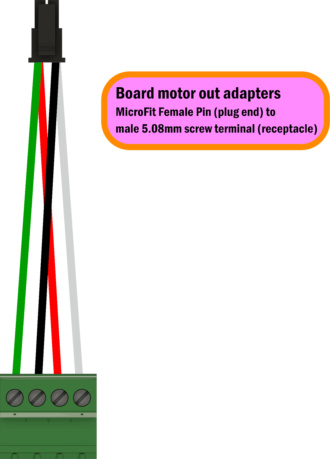
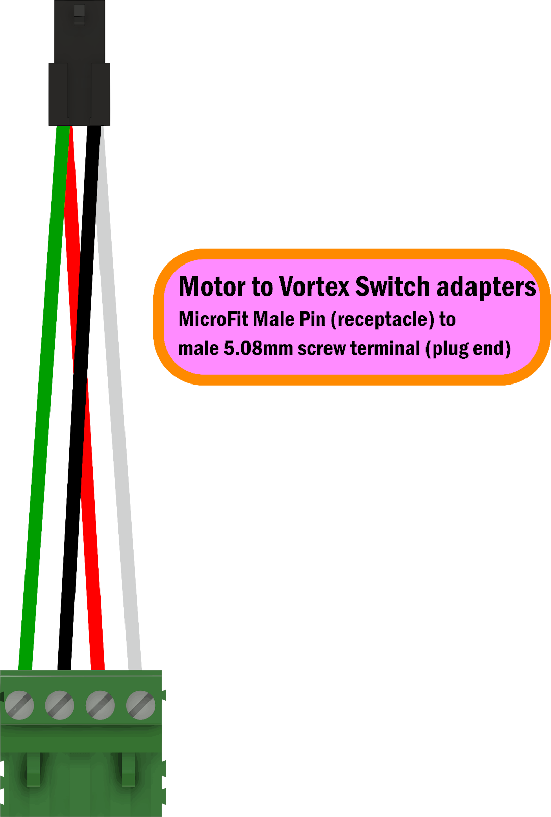
My next mission was to handle the wiring…ugh…the variety of connectors. Luckily, I teach electronics, so I had some connectors and tools on hand. After an Amazon and a DigiKey order I was able to make the necessary adapters.
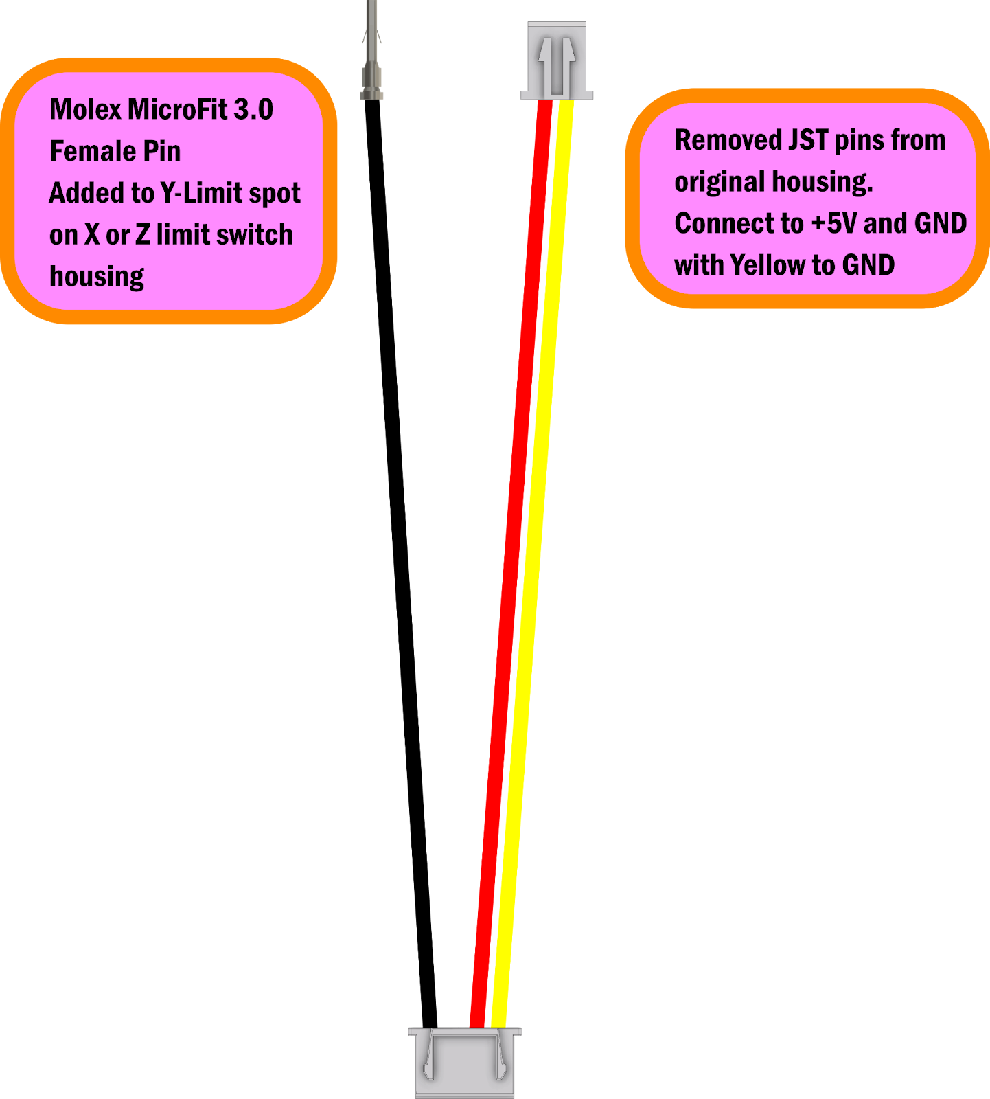
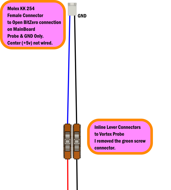
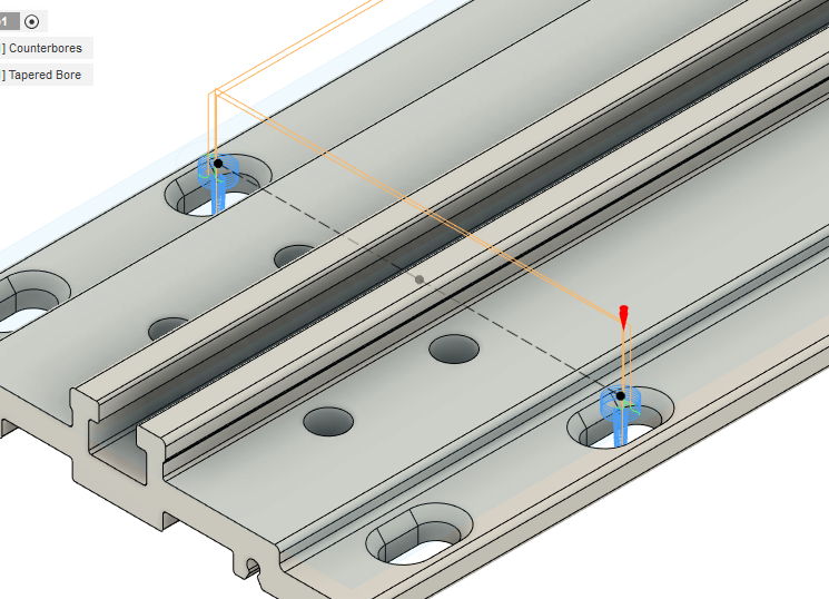
After I got these adapters made, I thought I’d just mount the thing, clamp the Y and go. But, how do I mount the thing? Well, gSender has a built-in gcode generator for mounting the Vortex (They use ¼-20 threaded inserts). There’s a problem though, because I don’t have a Longmill…I have a beast of a machine called the Shapeoko Pro. Not to worry, I used their open source files to generate gcode for the mounting holes that would fit on the MDF slats on the Pro. I generated some counterbores and tapered bores to match the taper of the threaded inserts. I also set my Y-Zero in Fusion to be on the centerline between the two left holes. That way, I could decide where the Vortex fit the best, zero Y there, and hit the slats exactly as planned. gSender also generates gcode for hole pairs, but I’m comfortable with my Fusion workflow so I went with that.
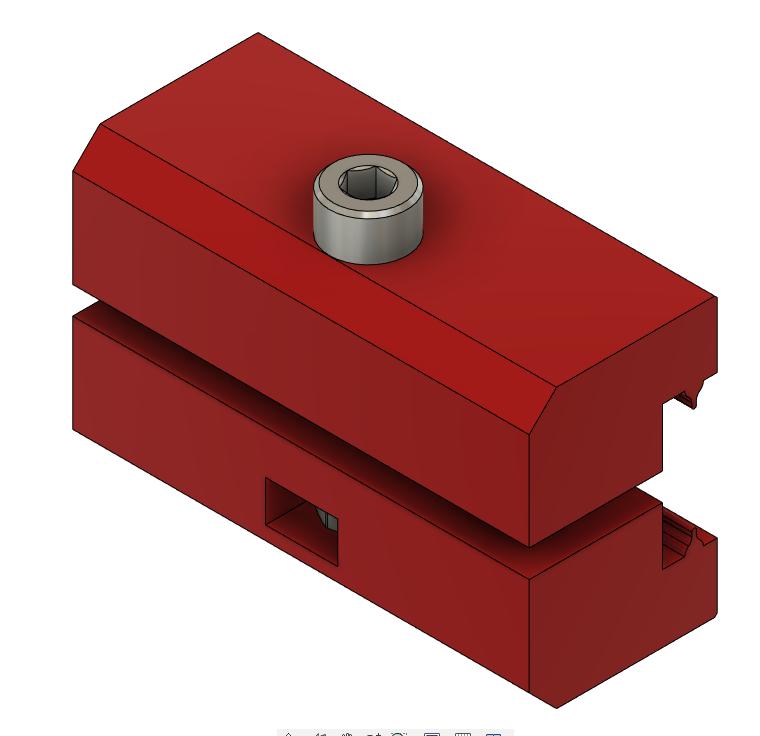
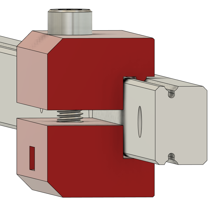
Great…easy. Now I just have to clamp it and go! I tried every which way to clamp the Y-axis on the SOPro, and I could not find a consistent method that prevented the Y from moving. After way too long, I finally came up with little 3D printed linear rail clamps. They clamp on the Y-rails in front and back of each Y-plate. I made a split clamp design, so I don’t have to slide them on from the front and rear of the machine. That’d be obnoxious on an XXL. Here’s what those look like:
Once that problem was solved, I was ready to go.
The procedure is pretty easy:
- Home the Shapeoko normally.
- Use gSender to set “Y-alignment”…this basically ensures that your X-axis is centered on the Vortex. I chucked up (doesn’t sound right) an aluminum tube to do this because the Vortex chuck is too tall to run the probe routine on the chuck. I’ll probably write a macro to do this without the tube eventually.
- Once aligned, I installed and tightened the clamps (while the Y is still powered).
- Power down, flip switch, power up.
- Set rotary mode in gSender (this adjusts the steps/mm for rotation)
- Home machine again…it’s fun to see the Rotary axis home!
- Set X-zero, as normal, by eye.
- Set Z-zero using the built-in probe routine, probing the chuck. This sets Z-zero in the center of the stock which makes sense for rotary jobs.
- Run the job!
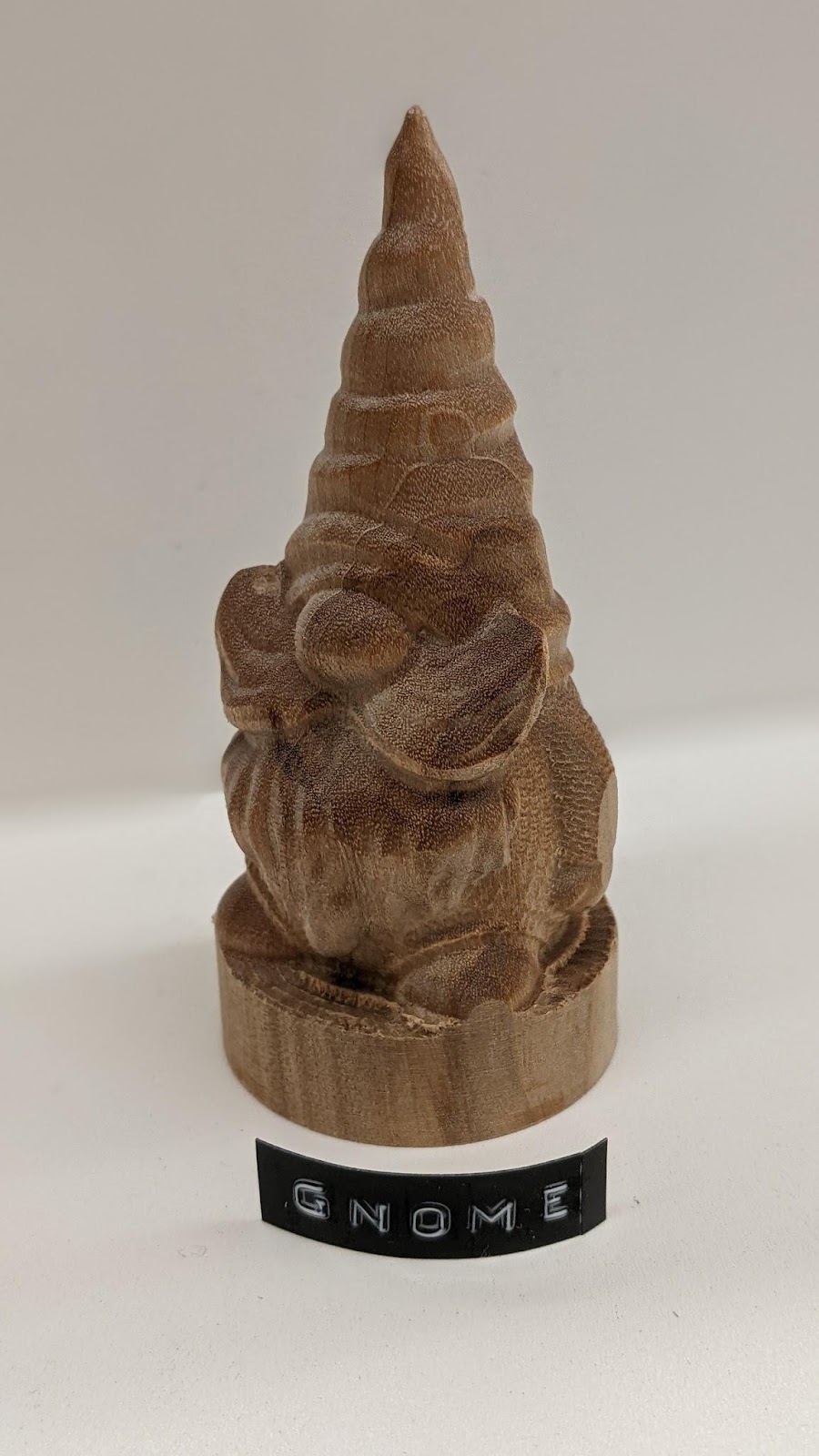
I downloaded a gnome stl by Body3D on Printables . I used V-carve Pro (v 9.5) and a custom post processor to generate the gCode. I used a flat ⅛” tool for the roughing, and a tapered ball (0.5mm tip) for the finish. I rarely do 3D reliefs, so I was impressed with the results.
Sorry for the long post! This was a fun project to get working, and it’s so cool when things just work! Not sure of my next rotary project, though a custom tap handle sounds like an obvious one.
Let me know if you have any questions. As always, I can share any STLs, files or post processors if you’re interested.
TLDR: Made my Shapeoko spin.