I have purchased the Longmill MK3 and as I await its release I am going over several different ideas.
I am thinking to get the most out of the space to make a tilt table that will hold the MK3 vertically when stored ( not sure about running it vertically as the added stress to the machine ) but also be able to tilt it back and it locks to a horizontal work area and also be able to tilt forward and have a blank work area when doing other projects or work when the MK3 is not in use… Would the MK3 be ok unside down if not in operation?
OR I was thinking of building a standard table but that houses the MK3 on a bottom shelf and have a blank work area at normal height?
Thoughts are greatly appreciated and thank you for your feedback.
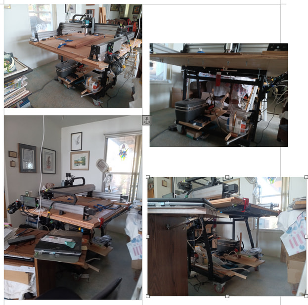
Our Sienci LongMill MK2.5 has been mounted on the Rockler tilt cart. The pins thru the sturdy steel legs had to be upgraded.
At each side of our ~3/4-inch plywood base there sits a 3/4-inch underboard for the CNC’s Y side-rail. These are bolted together. The base is bolted directly to the tilt-cart’s sturdy steel frame. The frame has a lever that clips it into horizontal position.
In this configuration there are spaces that can be cut clear through for setting clamps below the base for mounting stock vertically when desired; examples appear on youtube for their use for shaping end joints, mortise and tenon both.
The shapes of spoilboard tiles can correspond.
Metal reinforcements could be added with bolts or screws to the base and/or to the cart frame. (The 1/4-inch steel planks we got for Y underboards seem overkill. Heavy.)
The CNC on this cart has sturdy wheels for moving it handily and having access on all sides. With the height of the Z bridge screw and motor, it does take a doorway wider than usual even when tilted.
The cart’s leg structure includes a rectangular frame just above the casters. There is room for storage of boards, jigs and tools. While the cabinet shown on the Rockler site for that space, however, had dimensions preventing the tilting, putting a removable lightweight sliding shelf under there that can be locked in place, is tempting.
This may be lighter than a wooden-bench-like structure such as IDC’s or some in the Sienci tilt-CNC examples. It’s bottom line, though, that the CNC kit ships at 75 pounds and the cart almost that. On the other hand, the total weight of a jointer, a planer, etc. is more. And not easy to move, load, or be re-assembled.
It’s a big decision ; Good luck with it. Let us know, if you would, what you come up with.
Photos attached, hopefully clear enough. Top shows thru-bolted “soles” under the CNC Y-axis rails to maximize Z. Visible in the side views are sturdy steel support frame, large locking casters, red bent steel latch in middle of crossbar between the vertical legs for locking table horizontally, and red fingers at back, lowering edge to keep loaded boards from slipping down when moving tilted. Ships at 75 lb. Plus the CNC. Both sturdy and heavy. Cart steady but movable.
Underside shows steel legs and struts of rectangular tubing. Low rectangular support frame has heavy steel triangles welded to underside at the corners, where the large locking casters are attached. Pins for pivoting the top lie on the angled legs; there are safety lock-pins on each side as well (had to buy a different size) and a red lever in the middle of the crossbar between the vertical legs can latch the upper steel frame to horizontal position.
Our CNC base sheet is simply bolted directly to the steel upper frame. Sealed plywood was used but Sheet Aluminum might be better. (Holes for the attachment bolts were extended clear through the tubes by drilling, and large Fender washers used for spreading the pressure exerted by the bolts’ wingnuts. ) These boltheads lie flush with the upper table surface so they are inset into the back of spoilboard tiles overlaying them. Between spoilboard tiles T-track was screwed down with tiny woodscrews to the base. Note that deep clamps and vises can be readily attached to the thin edges, especially front and back.
Not only is there lots of space under the benchtop, the base can be pierced. This accessible underspace allows for setting up under-bench clamping of workpieces vertically. Clamp to the leg thru a hole? Maybe a backing with dogholes or tracks as seen in some great videos? Might be a bridge between the table’s support frame and the crossbar 9 cm below between the vertical legs? Clamped? Bolted? The bars separate when the base is tilted up. Is that ok? Ideas?