Tramming my 30"x30" longmill

Been wanting a CNC for 4 years, finally pulled the trigger on a 30"x30" Longmill, and I’m loving it…not a McDonald’s drop :joy:.

I’ve been using Easel, Carbide Create, and use Gcode Sender, with only operator errors, for the most part. Anyhow, I’m starting to see tram issues on all 3 axis.

I’ll try to sum this up as best as possible, without writing a book. Order my Longmill, and assembled it per instructions, online and youtube video that’s out there. Made my table, as sturdy as possible, with .75" MDF, and topped it with 4" wide x .75" spoil boards and t track. Surfaced it with a Whiteside 6210, and started carving right away, with no issues, other than beginner mishaps…got a few door stop pieces now :joy:.

I started to visually notice differences in depth on my pieces I’ve made, and started researching what could be going on, which led me to tramming my machine. I made a Z rod out of .25" round stock, that would cover a 30" radius, chucked it up, zeroed at a random corner, and started checking the surface… :grimacing:. I saw as much .10" from one corner to a mid point side, and there wasn’t really any consistent decline to lead it to that. My entire board had very random rises and drops throughout. So I got to checking all my v wheels, backlash nuts, making minor tweaks, and just doubling down on touching every single bolt and nut to make sure everything was tight. Looking at my numbers from the first go round of measuring every corner and mid point, I decided to add one small washer per side on the Z rail bottom wheels. That made it worse, so I moved them to the top, and it seemed to make my numbers in the right direction, so I said to heck with it, and sent it on another surfacing mission, just to see if I could get it to a more tolerable consistency.

Well, as soon as it started on its 3rd round of X travel in the front, I saw the dreaded waves of dismay. The first time I surfaced my table, they weren’t as bad. You could see them, but not really feel them much. Trying to figure out how I could shim it out, or anything else, I talked to my machinist, and after reading up on some forums on here and else where, I barrowed an indicator from my machinist at work. On the Z axis alone, I’m seeing a consistent +.021 rise, at 180deg out, in a 3" radius. Basically just turning the router with the indicator mounted to it. On the table itself, from right to left on the X axis, on the back side of the board, it’s out -.013", and from that point to the front left side on the Y axis, it goes to +.023".

I’m waiting to hear back from someone at Sienci, to help get this figured out. But any help on here is more than welcome. I’m going to attempt to draw this out on here, in a box with my dimensions.

                                          BACK OF LONGMILL

-.013                      +.01                         0.0 (my zero point)


+.01                      -.016                       -.003
                      (middle of board)

+.023                    +.01                       +.013 


          INDICATOR ON ROTATIONAL Z AXIS ONLY (3" RADIUS)

                             0.0 (my zero, towards back of board)

         +.012                     +.008

                         +.021 (front side direction)
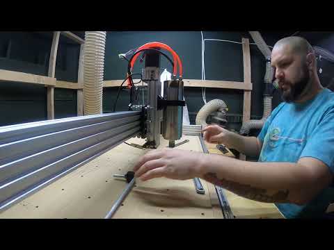
1 Like

Jason…did you ever get a response from Sienci? I’m in the same boat as you and am working on trying to get my LM trammed. Interested in hearing how your situation worked out.

Did either one of you find the problem ?

Same problem here also. Sure would be nice if there was a fine adjustment built in for it.

i cant find any info on how to tram my longmill 30 30, i was tole that sienci had instructions on it but i cant locate them on the web site, has anyone figured out hot to tram yet, from all indications, the left side of my bit seams to be a bit lower than the right side

1 Like

You will need to make or buy a spindle square tool.

I made mine using some mild steel round stock I got at Home Depot and took to work and drilled and tapped a hole for a 1/4-20 screw to go into and hole a dial gage I got from Harbor Freight. Mill a hole in the top for another piece of round stock to sit in. After that, drilling and tapping a hole in the other end of the rod lets you fit the part that will be held into the spindle with a set screw. Here’s a picture of the tool as well as the blueprint I made for it if you’d like to copy. It is very simple. You could also just drill more holes at different distances for a smaller tram as well. Or even better yet have the part that comes from the spindle have a thru hole and then a set screw so you can adjust the length and put double dials on it, one for each side to double it as a 7.5" dual dial tram bar. Make it out of 1/2" steel and it shouldn’t flex enough to matter.


TRAM BAR 15 IN_CENSORED.pdf (2.0 MB)

After that, the general consensus is that “the Longmill should be square enough out of the box” from responses I’ve gotten, and customer support directed me here to the forums to check with other users where there hasn’t been much productive discussion about.

Here’s what I have experimented with so far:

  • The V wheel tightness can be adjusted so that the angle is different, but this isn’t really ideal. Regardless, make sure they’re nice and snug and as even as possible at this point.

  • If you are out of square in the X direction you will just need to shim the Y rails unfortunately.

  • If you are out of square in the Y direction you can try and place shim stock under the spindle mount but if you are using the one that came with the machine it is a horrible experience. The mount is already a poor design choice for the reasoning that it has nothing to stop it from flexing since there is only horizontal support and no vertical support. I completely replaced mine since I was already using a heavier spindle anyways and really exaggerated its deflection. I’ve attached a pic below.

Alternatively, you could attempt to shim the Y axis in the direction needed to flatten the spindle out as well, but it might cause a lot of trial and error with the shimming you did on the Y axis to balance out the X axis.

The modification I did was fairly simple. You could probably do it all with a drill press or even a power drill if you have one with the right bits.

I aligned the new mount to the Z plate and marked where the new mounting holes needed to be via transfer punch. Those were drilled out to a .350" thru hole so to use 4" long 5/16" (.315") bolts in. The extra slop is there because this way I can adjust for square on the X axis at the spindle mount in case it needs minor adjustments and so not as much shimming work needs to be done. Additionally, the new spindle mount had to have pockets drilled into it for clearing the M5 and M3 screws for the Delrin Anti-Backlash nut and the linear rail screws to clearance. The M5 screws on the V wheels also needed replaced with 20mm screws instead of the stock 25mm screws because the nuts / bolt heads for the new mount would not clear while sliding up and down. A picture of what that looks like below as well. The advantage of this kind of mount is that since it is taller it has more surface area to contact the spindle with to hold onto it. It’s height also allows for two rows of screws instead of one, which means it will not deflect like the thin stock one does. And finally, when I need to adjust for square on the Y axis, I can simply loosen the two bolts on the bottom and insert some shim stock, tighten, check and repeat if necessary.

It still isn’t the most ideal way to adjust for squareness. I need to hold the front of the bolts with channel locks lightly as to avoid crushing the threads (hence why they are grade 8 hardened steel) to tighten and loosen the nuts. That’s also why the bolts are in backwards. It would be far too difficult to tighten the nuts from behind due to no space to fit a wrench. Eventually I would like to create a bracket for a set screw to sit in that will push the spindle askew in either direction, so it makes it much easier to make fine adjustments without needing to do as much as turn a hex key.

An alternative modification could be to drill pockets out for the screws to recess into for clearance, but I didn’t want to go too far and weaken the plate.

I believe this is a big design flaw in the Longmill and I hope this problem is addressed in future versions. As far as I am concerned, there is no way to adjust for squareness in a precise way at the moment and the best way to do it is to modify it as I have.

1 Like

I don’t think shimming the router is the correct way to tram. I think the linear guide rails should be perpendicular to the spoil board to allow the Z axis to travel straight up and down. If you just shim the router then it may be true to the spoil board, but still travels at an angle. I am adding washers to the lower wheels to straighten out the linear rails.

@Markf99 Mark: Am I correct in thinking that putting washers on the lower wheels will address nod, but it won’t address tilt?

correct. I was able to adjust the tilt by loosening the bolts for the router mount and tweaking it that way.

1 Like

If you’re using the Makita router as I am, I was having trouble getting it to surface also.
After checking the mounting hardware and the other stuff listed here, I discovered that you need to raise the router slightly in the mount. The radiused transition on the router needs to be above the clamp edge to hold it squarely.

5 Likes

First if you put your machine together properly to begin with it should be perfectly square from that point. Check all the screws in the feet and make sure they are tight. If one is loose it could cause a problem. Then make sure the screws holding the feet to your table are tight. Not too tight to split the printed feet.

After that the only spot you should adjust the machine to tram it is behind the router in the adjustment plate. You can get brass shim material from lee valley if you need some. There are no videos of tramming the longmill but there are some that are similar.

Both of these videos are great because they are home made machines. They use the same principles as the longmill to attach the routers or spindles.

1 Like

If you go to IDC woodcraft Garrett
will show you how to tram the longmill Mk2 I’m in the process of doing it.

The process doesnt change because its a MKI or an MKII guys its the same process.

1 Like

As a machinist I have other thoughts. To do a sweep with an indicator chucked in the router, the spoil board has to be perfectly flat to get readings that mean anything. And if the router isn’t right, how are you going to get that flat spoil board?
My first attempt to level my spoilboard with side to side travel made it look like sawtooth design with the deeper cut in the back, so it seems I could put shim washers behind the top wheels tilting the top of the router towards the front. So far I haven’t tried making any adjustments, this just happened today. I have teamed mills in the machine shop, but they are made adjustable.
Please if you have come up with any solutions please let me know.
Phil